Phonic DYN2000 User manual

DYN2000
DYNAMIC PROCESSOR
English
User’s Manual

1. Read these instructions before operating this
apparatus.
2. Keep these instructions for future reference.
3. Heed all warnings to ensure safe operation.
4. Follow all instructions provided in this document.
5. Do not use this apparatus near water or in locations
where condensation may occur.
6. Clean only with dry cloth. Do not use aerosol or liquid
cleaners. Unplug this apparatus before cleaning.
7. Do not block any of the ventilation openings. Install
in accordance with the manufacturer
’
s instructions.
8. Do not install near any heat sources such as radiators,
heat registers, stoves, or other apparatus (including
amplifiers) that produce heat.
9. Do not defeat the safety purpose of the polarized or
grounding-type plug. A polarized plug has two blades
with one wider than the other. A grounding type plug
has two blades and a third grounding prong. The wide
blade or the third prong is provided for your safety. If
the provided plug does not fit into your outlet, consult
an electrician for replacement of the obsolete outlet.
10. Protect the power cord from being walked on or
pinched particularly at plug, convenience receptacles,
and the point where they exit from the apparatus.
11. Only use attachments/accessories specified by the
manufacturer.
12. Use only with a cart, stand, tripod, bracket, or
table specified by the manufacturer, or sold with
the apparatus. When a cart is used, use caution
when moving the cart/apparatus
combination to avoid injury from tip-
over.
13. Unplug this apparatus during lighting
storms or when unused for long
periods of time.
14. Refer all servicing to qualified service personnel.
Servicing is required when the apparatus has been
damaged in any way, such as power-supply cord or
plug is damaged, liquid has been spilled or objects
have fallen into the apparatus, the apparatus has
been exposed to rain or moisture, does not operate
normally, or has been dropped.
IMPORTANT SAFETY INSTRUCTIONS
CAUTION: TO REDUCE THE RISK OF ELECTRIC SHOCK,
DO NOT REMOVE COVER (OR BACK)
NO USER SERVICEABLE PARTS INSIDE
REFER SERVICING TO QUALIFIED PERSONNEL
The lightning flash with arrowhead symbol, within an
equilateral triangle, is intended to alert the user to the
presence of uninsulated
“
dangerous voltage
”
within the
product
’
s enclosure that may be of sufficient
magnitude to constitute a risk of electric shock to persons.
The exclamation point within an equilateral triangle is in-
tended to alert the user to the presence of important operat-
ing and maintenance (servicing) instructions in the literature
accompanying the appliance.
WARNING: To reduce the risk of fire or electric shock, do
not expose this apparatus to rain or moisture.
CAUTION: Use of controls or adjustments or performance
of procedures other than those specified may result in
hazardous radiation exposure.
The apparatus shall not be exposed to dripping or splashing and that no objects filled with liquids, such as vases,
shall be placed on the apparatus. The MAINS plug is used as the disconnect device, the disconnect device shall
remain readily operable.
Warning: the user shall not place this apparatus in the confined area during the operation so that the mains switch
can be easily accessible.
CAUTION
RISK OF ELECTRIC SHOCK
DO NOT OPEN

Dynamic Processor
DYN2000
Phonic reserves the right to improve or alter any information suppied within this document without prior notice.
V1.2 NOV 12, 2007
TABLE OF CONTENTS
INTRODUCTION....................................................................................................4
FEATURES..........................................................................................................4
QUICK SETUP .....................................................................................................4
FRONT PANEL DESCRIPTION..................................................................................5
Expander/Gate Section .........................................................................................5
Compressor Section ............................................................................................5
Master Section ...................................................................................................7
REAR PANEL DESCRIPTION ..................................................................................8
SPECIFICATIONS..............................................................................................9
DIMENSIONS......................................................................................................10
BLOCK DIAGRAM................................................................................................11

4 DYN2000
INTRODUCTION
Congratulations on choosing another quality product
from Phonic. The DYN2000 Dynamic Processor with
Compressor, Limiter and Gate functions is the ideal
product for sorting out any excess noise, keeping
those high peaks under control and smoothing out
any vocal or instrumental sounds in your audio. We
strongly suggest that you read this user’s manual
thoroughly to allow yourself to make full use of this
product. After reading, store the manual in an easy
to remember location. This will enable you to nd it
quickly in case there is something you missed the
rst time around.
FEATURES
Stereo or Dual Mono operation of gate,
compressor and limiter functions
Select between soft knee and hard knee
operation
Expander/Gate function features variable
release time and +15dBu max. threshold
Separate sidechain inserts with selectable Low
Frequency Shelf
The limiter function provides total control of
maximum peak levels at the output regardless
of any other control
System bypass buttons on both channels, useful
for comparing processed and unprocessed
signals
8-Segment LED display, showing gain reduction
up to 30dB
Balanced XLR and 1/4” TRS inputs and
outputs
QUICK SETUP
1. Make sure your unit is off. Preferably remove the
AC power cable.
2. Connect all of your required output devices to
the DYN2000’s inputs. If it’s a stereo device, use
both of the unit’s channels and push the Stereo
Link button in. If you’re using a mono signal,
simply use a single channel. The other channel
will then be free for a second mono signal.
3. Connect all of your required input devices to the
DYN2000’s output connectors. This may include
ampliers or mixers (if you’re using the DYN2000
on a mixer’s insert point).
4. Connect any additional signal processors you
wish to make use of to the unit’s Sidechain insert
points. This will require a y-cord with a 1/4” TRS
jack on one end and two 1/4” TS jacks on the
other.
5. Turn your devices on in this order: instruments,
mixer, signal processors, amps/speakers.

5DYN2000
FRONT PANEL DESCRIPTION
Expander/Gate Section
A noise gate is a signal processor that turns off or
signicantly attenuates the audio signal passing
through it when the signal level falls below a user
adjustable threshold.
1. Expander/Gate Threshold Control and LEDs
This control adjusts the threshold of the gate, basically
determining how much of the input signal will pass
through to the output. When the threshold control is
in the OFF position, all signals are allowed through
the gate. Turning it all the way clockwise will ensure
only signals over the +15 dB are allowed to pass
through, affectively limiting the noise level. The two
LEDs indicated when input signals are above (green
LED) or below (red LED) the selected threshold.
One way to easily and effectively set the gate
threshold is to first turn this control to the OFF
position. Play your audio through the DYN2000 and
turn the threshold control up until the red Gate LED
comes on. This is helpful in removing hiss from tape,
guitar amps, and so forth.
NB. The DYN2000’s expansion ratio is internally fixed to
approximately 10:1, helping to eliminate residual noise often
associated with gating.
2. Sidechain Enable Button
This switch enables the sidechain, allowing users
to use the 1/4” TRS sidechain connector on the
rear of the DYN2000 to send their signal to external
processors and receive the processed signal back.
If there is nothing connected to the sidechain loop,
this button has no affect.
3. Expander/Gate Release Control
This control sets the speed at which the gate closes
once the input or sidechain signals fall below the
selected threshold. Set this control to a slower setting
if vocals or acoustical instruments are used; set to
fast for tighter percussion.
1 2 3 4
5 15
6
97 8 12 13 1614 17
10 11
4. Contour Button
Push this button in to ensure the DYN2000 is less
sensitive to low frequency energy, ensuring there’s
no loss of audio – particularly helpful when using
mixed program material.
Compressor Section
Compressors are signal processors that reduce
signals over a user-dened threshold by a user-
dened amount/ratio.
5. Gain Reduction Meter
This meter gives users a visual ideal of how much
the signal is being attenuated by the compressor and
gate functions.
COMPRESSOR/LIMITER
Gate
Attack
V
t
Release
Rate
+ 10 dB
+ 5 dB
- 10 dB
- 15 dB
- 25 dB
- 30 dB
- 45 dB
OFF
This diagram shows the signal cut at various rate settings.

6 DYN2000
6. Compressor Threshold Indicators
These three LEDs indicate the relationship of the
input signal level to the threshold of compression. The
green BELOW LED is On when the signal is below
threshold and the red ABOVE LED is On when the
signal is above threshold.
Note: Even when no input signal is received, these LEDs may
icker when the power is activated or deactivated.
7. Compressor Threshold Control
This control allows users to adjust the level at which
compression to the input signal will kick in, thus
avoiding distortion and protecting your amplier and
speakers. Turning it clockwise will raise the threshold,
thus squeezing signals at a higher level and reducing
the amount of compression applied to the signal.
8. Hard Knee Button
With this button pushed in, the DYN2000 applies a
hard-knee style of compression to the input signal.
What this means, exactly, is that when the signal level
reaches the selected threshold, the compressor will
kick-in instantly and start compressing the signal at
the selected threshold. When released, however,
a soft-knee style of compression is used, basically
easing into the compression just prior to hitting the
threshold.
9. Ratio Control
This allows users to adjust the ratio between the
input signal received by the DYN2000 and the
compressed output signal. When this rotary VR is
set to 1:1, there will be no compression applied to
the signal. When it is set at 2:1, any input signal over
the selected threshold is compressed to half. When
it is set to ∞:1, any signal over the threshold setting
will be completely removed (affectively making the
compressor a ‘limiter’).
1 2 3 4
5 15
6
97 8 12 13 1614 17
10 11
output level
output level
Input level
Input level
Hard Knee
Soft Knee
These diagrams show hard knee and soft knee compression.
( 5 dB Compression )
Threshold
1:1
2:1
6:1
OUTPUT
INPUT
(Ratio)
14
12
10
8
6
4
2
0
0 2 4 6 8 10 12 1 4
This diagram shows typical compressions at various ratios.
10. Compressor Attack Control
This control allows users to adjust the speed at which
the compressor function will take effect after a signal
above the selected threshold has been detected.
A fast attack time will be more noticeable, but will
control excessive peaks much easier. A slower
attack time, however, will be far less audible and still
successfully compress excessive signals.

7DYN2000
11. Compressor Release Control
The release determines how fast the compression
circuitry will return the input to its original level after
levels have fallen below the selected threshold. A fast
release time will rigidly follow the program material,
whereas a slower released time will allow for much
smoother compression.
OUTPUT
Attack Release
(Threshold)
Compression
v
t
10 dB
6 dB
2 dB
12. Auto Attack and Release Switch
Pushing this switch in will allow the DYN2000 to
automatically determine the best attack and release
times based on the program material put before it.
When activated, it will affectively render the attack
and release controls useless.
This diagram shows how the attack and release work.
Master Section
13. Output Gain Control
This control adjusts the amount of gain applied to the
signal at the output stage (meaning the compression
and gate thresholds are not affected).
14. Bypass Button
The DYN2000 include a hard-wired bypass circuit,
which is active even while the power to the unit is off.
While using the unit, however, the bypass is useful in
comparing processed and unprocessed signals.
15. Output Level Meter
This 5 segment level meter gives users a visual
indication of when the output signal reaches certain
levels. To make the most of your audio, set the output
gain control to a level that will ensure the level meter’s
clip LED lights up only occasionally.
16. Limiter Control and Peak LED
Adjusting this control will allow users to apply a
limiter to their already compressed signal, affectively
protecting speakers against large transient sounds,
as well as other excessive peaks and overloads.
Users are able to adjust the limiter between 0 and
+20 dB, with +20 dB being the setting where the least
amount of limiting occurs. The Peak LED will light
up whenever a signal reaches the level set by the
limiter control and is attenuated.
17. Stereo Couple Button
Pushing this button in switches the DYN2000
between stereo and dual mono modes. In stereo
mode, channel 1 acts as the master control and all
compression and gating is applied to both channel
1 and 2 inputs. In dual mono, both channels work
independent of one another.
1 2 3 4
5 15
6
97 8 12 13 1614 17
10 11
8 DYN2000
19 18 21
22 20
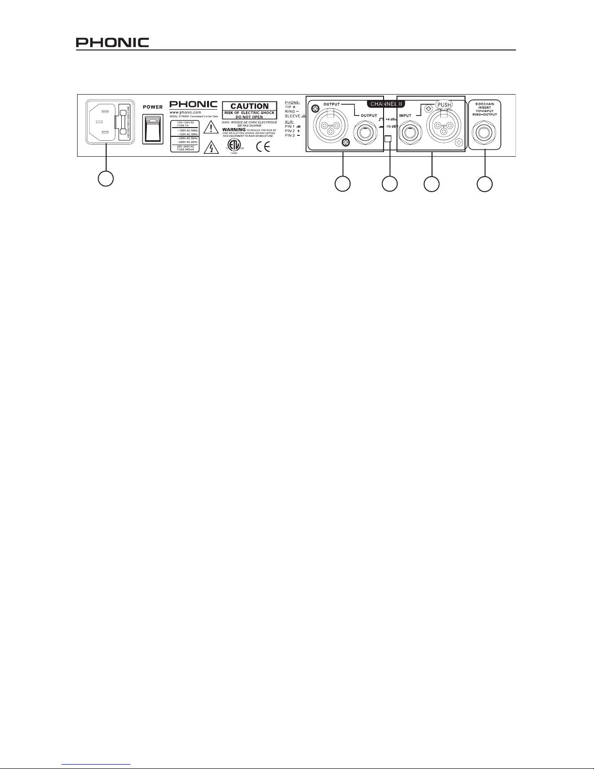
REAR PANEL DESCRIPTION
18. Channel 1 and 2 Inputs
These balanced XLR and 1/4” TRS phone jack
connectors are for the input of signals to the
DYN2000. Please note that only one of these inputs
should be used on each channel at any one time.
19. Channel 1 and 2 Outputs
These balanced XLR and 1/4” TRS phone jack
connectors are for the output of already processed
signals from the DYN2000. Unlike the input jacks, all
of these outputs can be used simultaneously.
20. Operating Level Select Switch
This switch swaps the input and output levels of the
corresponding channel between -10 dBV (consumer
level) and +4 dBu (professional level).
21. Sidechain Insert Points
This 1/4” TRS connector allows users to send and
receive signals to and from external processors using
a special y-cord (see diagram). This allows users to
apply additional effects to their signals. Pushing the
sidechain button (see point number 2) on one or both
channels will make use of the unit connected to the
corresponding sidechain insert.
22. AC Power Cable Receptacle and Power
Switch
This is a standard AC receptacle that accepts
IEC-type power cords. We suggest using the cord
provided along with this unit only, and be sure to
check local voltage levels before connecting the
cord. The accompanying power switch will turn the
DYN2000 on and off when power is supplied to the
unit.

9DYN2000
SPECIFICATIONS
INPUT
Connector: 1/4” TRS and XLR, Floating Balanced; XLR: Pin 2 hot Phone: Tip Hot HI
Impedance: >50kΩ balanced, >25kΩ unbalanced
Maximum Level: +24dBu, Balanced or Unbalanced
CMRR: >40dB at 1kHz, typically >55dB
SIDECHAIN INSERT
Connector: 1/4” TRS Phone, Normalled: Ring = Output (send); tip = Input (return)
Impedance: Tip = >10kΩ (Input), Ring = 2kΩ (Output)
Maximum Level: +24dBu
OUTPUT
Connector: 1/4” TRS phone and XLR oating balanced, XLR: Pin 2 and Tip Hi
Impedance: 120Ω balanced, 60Ω unbalanced
Maximum Level: +21dBu,>+20 dBm into 600Ω, balanced or unbalanced
Frequency Response: 20Hz - 20kHz; +0, -0.5dB,Typical 3dB points are 0.35Hz and 110kHz, unity gain
Noise: <-90dBu, 22Hz to 22kHz, no weighting, unity gain
THD + N: Typically <0.04%; Any Amount of Compression Up to 40dB@1kHz
SMPTE IMD Typically <0.08% @ +10dBu (15dB Gain reduction)
COMPRESSION
Threshold Range: -40dBu to +20dBu
Threshold Characteristic: Selectable easy or hard knee
Compression Ratio: Variable; 1:1 to Innity:1; 60dB Maximum Compression
Attack Time: Variable program-dependent; 3ms to 340ms for 15dB gain reduction
Release Time: Variable program-dependent; 200dB/Sec to 3dB/Sec
EXPANDER/GATE
Threshold Range: OFF to +15dBu
Expansion Ratio: 10:1
Maximum Depth: >60dB
Attack Time: <500µs (from Maximum Depth)
Release Time: Adjustable, 30ms to 3sec (to 30dB attenuation)
SYSTEM
Limiter Threshold Range: 0dBu to +20dBu
Gain Adjustment Range: Variable; -20dB to +20dB
Interchannel Crosstalk <-80dB, 20Hz to 20kHz
Dynamic Range: >115 dB
POWER
Power Consumption: 15 Watts Maximum
Operating Temperature: 0°C to 45°C (32°F to 113°F)
PHYSICAL
Dimensions: 1.7” x 19” x 7.2” (4.4 cm x 48.2 cm x 18.3 cm)
Weight: Net weight: 5.05 lb (2.29 kg)
Shipping weight: 7.20 lb (3.27 kg)
Note: 0dBu = 0.775Vrms
Note: Specications subject to change without notice.

10 DYN2000
DIMENSIONS
482 / 19”
44 / 1.7”
183 / 7.2”
* All measurements are shown in mm/inches.

11DYN2000
BLOCK DIAGRAM

Phonic America Corporation
6103 Johns Road, #7
Tampa, FL 33634
(813) 890-8872
http://www.phonic.com
TO PURCHASE ADDITIONAL PHONIC GEAR AND ACCESSORIES
To purchase Phonic gear and optional accessories, contact any authorized Phonic distributor. For
a list of Phonic distributors please visit our website at www.phonic.com and click on Get Gear. You
may also contact Phonic directly and we will assist you in locating a distributor near you.
SERVICE AND REPAIR
Phonic has over 100 service centers worldwide. For replacement parts, service and repairs please
contact the Phonic distributor in your country. Phonic does not release service manuals to
consumers, and advice users to not attempt any self repairs, as doing so voids all warranties. You
can locate a dealer near you at www.phonic.com.
WARRANTY INFORMATION
Phonic stands behind every product we make with a no-hassles warranty. Warranty coverage
may be extended, depending on your region. Phonic Corporation warrants this product for a
minimum of one year from the original date of purchase against defects in material and workman-
ship under use as instructed by the user’s manual. Phonic, at its option, shall repair or replace the
defective unit covered by this warranty. Please retain the dated sales receipt as evidence of the
date of purchase. You will need it for any warranty service. No returns or repairs will be accepted
without a proper RMA number (return merchandise authorization). In order to keep this warranty
in effect, the product must have been handled and used as prescribed in the instructions accom-
panying this warranty. Any tempering of the product or attempts of self repair voids all warranty.
This warranty does not cover any damage due to accident, misuse, abuse, or negligence. This
warranty is valid only if the product was purchased new from an authorized Phonic
dealer/distributor. For complete warranty policy information, please visit http://www.phonic.com.
CUSTOMER SERVICE AND TECHNICAL SUPPORT
We encourage you to visit our online help at http://www.phonic.com/help/. There you can find
answers to frequently asked questions, tech tips, driver downloads, returns instruction and other helpful
information. We make every effort to answer your questions within one business day.

Other manuals for DYN2000
1
Table of contents
Other Phonic Music Pedal manuals


Popular Music Pedal manuals by other brands


TC Electronic
TC Electronic TUBE PILOT OVERDRIVE quick start guide

Electro-Harmonix
Electro-Harmonix Grand Canyon manual

Electro-Harmonix
Electro-Harmonix DELUXE ELECTRIC MISTRESS quick start guide

Mooer
Mooer Micro Series owner's manual

Blockhead
Blockhead Rhythm Maker BH4010 Quick setup guide

MORLEY
MORLEY PWA-IIES manual


