Phonic WM70 User manual

1
WM SERIES
WM70 Wireless Transmitter
Wireless Gear For The Performer Speakers
ENGLISH
User’s Manual
OFFON
SIG/CLIP
WIRELESS TRANSMITTER

2WM SERIES
1. Read these instructions before operating this
apparatus.
2. Keep these instructions for future reference.
3. Heed all warnings to ensure safe operation.
4. Follow all instructions provided in this document.
5. Do not use this apparatus near water or in locations
where condensation may occur.
6. Clean only with dry cloth. Do not use aerosol or liquid
cleaners. Unplug this apparatus before cleaning.
7. Do not block any of the ventilation openings. Install
in accordance with the manufacturer
’
s instructions.
8. Do not install near any heat sources such as radiators,
heat registers, stoves, or other apparatus (including
amplifiers) that produce heat.
9. Do not defeat the safety purpose of the polarized or
grounding-type plug. A polarized plug has two blades
with one wider than the other. A grounding type plug
has two blades and a third grounding prong. The wide
blade or the third prong is provided for your safety. If
the provided plug does not fit into your outlet, consult
an electrician for replacement of the obsolete outlet.
10. Protect the power cord from being walked on or
pinched particularly at plug, convenience receptacles,
and the point where they exit from the apparatus.
11. Only use attachments/accessories specified by the
manufacturer.
12. Use only with a cart, stand, tripod, bracket, or
table specified by the manufacturer, or sold with
the apparatus. When a cart is used, use caution
when moving the cart/apparatus
combination to avoid injury from tip-
over.
13. Unplug this apparatus during lighting
storms or when unused for long
periods of time.
14. Refer all servicing to qualified service personnel.
Servicing is required when the apparatus has been
damaged in any way, such as power-supply cord or
plug is damaged, liquid has been spilled or objects
have fallen into the apparatus, the apparatus has
been exposed to rain or moisture, does not operate
normally, or has been dropped.
IMPORTANT SAFETY INSTRUCTIONS
CAUTION: TO REDUCE THE RISK OF ELECTRIC SHOCK,
DO NOT REMOVE COVER (OR BACK)
NO USER SERVICEABLE PARTS INSIDE
REFER SERVICING TO QUALIFIED PERSONNEL
The lightning flash with arrowhead symbol, within an
equilateral triangle, is intended to alert the user to the
presence of uninsulated
“
dangerous voltage
”
within the
product
’
s enclosure that may be of sufficient
magnitude to constitute a risk of electric shock to persons.
The exclamation point within an equilateral triangle is in-
tended to alert the user to the presence of important operat-
ing and maintenance (servicing) instructions in the literature
accompanying the appliance.
WARNING: To reduce the risk of fire or electric shock, do
not expose this apparatus to rain or moisture.
CAUTION: Use of controls or adjustments or performance
of procedures other than those specified may result in
hazardous radiation exposure.
The apparatus shall not be exposed to dripping or splashing and that no objects filled with liquids, such as vases,
shall be placed on the apparatus. The MAINS plug is used as the disconnect device, the disconnect device shall
remain readily operable.
Warning: the user shall not place this apparatus in the confined area during the operation so that the mains switch
can be easily accessible.
CAUTION
RISK OF ELECTRIC SHOCK
DO NOT OPEN

3
WM SERIES
WM Series
Wireless Gear For The Performer Speakers
CONTENTS
Phonic reserves the right to improve or alter any information suppied within this document without prior notice.
V1.1 FEB 14, 2006
INTRODUCTION....................................................................................................... 4
SYSTEM COMPONENTS ......................................................................................... 4
FEATURES................................................................................................................ 4
QUICK SETUP .......................................................................................................... 5
Single Channel Setup..........................................................................................5
Dual Channel Setup ............................................................................................6
TROUBLESHOOTING ...............................................................................................7
WM60 TRANSMITTER ..............................................................................................8
WM70 TRANSMITTER ..............................................................................................9
WM40-L AND WM40-R RECEIVERS ......................................................................10
SPECIFICATIONS....................................................................................................11

4WM SERIES
INTRODUCTION
Congratulations on your purchase of the
WM series of wireless accessories for
the Performer speakers. With either the
stereo or mono WM kits, you are now
fast on your way to becoming completely
wireless in your audio set up. The WM
modules are not only fantastic in style
and convenience, however; they are in-
credibly easy to use, as this manual will
no doubt prove.
Please have a thorough read of this
user’s manual before operating the WM
modules. Inside this guide you will nd
information on the ease of your wireless
set up, as well as some great trouble-
shooting tips and a complete run-down
on your modules’ features. After reading,
place the manual in an easy to remember
place so that you can come back to it in
future if ever necessary.
SYSTEM COMPONENTS
WM-SYS1 includes:
1x WM60 single channel transmitter
1x WM40-L receiver module
WM-SYS2 includes:
1x WM70 dual channel transmitter
1x WM40-L left channel receiver module
1x WM40-R right channel receiver
module
FEATURES
Common Features
●
Operates on a UHF band,
614~870MHz
●
16 selectable UHF channels preset
●
Internal squelch and mute circuit
mode can resist extraneous noise
●
Space-saving integrated compact
module
WM60 Additional Features
●
Single channel stand-alone transmit-
ter
●
Signal/Clip indicator
●
External power supply
WM70 Additional Features
●
Dual channel stand-alone transmitter
●
Signal/Clip indicator
●
Volume control to set the appropriate
level to avoid clip
●
Mono/Stereo switch for easy setting
in mono or stereo sound system
●
16 preset channel encoder will decide
the left and right channel frequencies
automatically
●
External power supply
WM40-L & WM40-R Additional Features
●
Left or Right channel receiver module
to be installed in any Phonic Performer
powered speaker
●
Power indicator
●
True diversity receiving mode

5
WM SERIES
QUICK SETUP
Single Channel Setup
With any one performer speaker, users
are able to wirelessly send a monaural
signal through the WM60 transmitter and
WM40-L receiver.
1. Plug the mixer’s main output (with a
line-level signal) to either the XLR or
1/4” input of the WM60 transmitter.
2. Connect the provided DC power
supply to the WM60’s power input
and an appropriate AC power source
and turn it on.
3. Adjust the channel on both the WM60
and WM40-L so they are identical. If
you wish to send and receive a sig-
nal successfully, this is of utmost im-
portance!
4. Adjust the WM60’s antenna into a
vertical position.
5. Slide the WM40-L receiver into the
Performer’s Wireless Module Re-
ceptacle on the top right hand side of
the speaker (right hand side, when
facing the rear of the speaker) and
screw it into place. Be sure to move
the module’s antennas (protruding
from the case) to either side of the
module. Ideally, the antennas should
be taped to the wall of the module
slot.
6. Set the WIRELESS / WIRELESS
MIC switch on the rear panel of the
performer speaker to the “Wireless”
Position, and set the wireless vol-
ume control to around the 3 o’clock
position.
7. Turn the WM60 on rst, then the Per-
former Speaker.
8. Provided you have a signal going out
of your mixer, and your Speaker is
turned on, the wireless transmission
should be working.
OFFON
SIG/CLIP
WIRELESS TRANSMITTER
WM60

6WM SERIES
Dual Channel Setup
With any performer speakers, users
are able to wirelessly send stereo sig-
nals through the WM70 transmitter and
WM40-L / WM40-R receivers.
1.
Plug the mixer’s main stereo output
(with a
line-level signal) to the left
and right inputs (both XLR and 1/4”
inputs can be connected to the com-
bo-jacks) of the WM70 transmitter.
2
.
Connect the provided DC power sup-
ply to the WM70’s power input and
an appropriate AC power source.
3. Adjust the channel on the WM70 and
both WM40s so they are identical. If
you wish to send and receive a sig-
nal successfully, this is of utmost im-
portance!
4. Make sure the WM70 is switched to
“stereo” mode.Turn the left and right
level controls to around the 3 o’clock
position.
5. Insert the left and right antennas into
the left and right antenna plugs on
the WM70, and leave them sitting
vertically for the best range.
6.
You can then insert the WM40-L
and WM40-R receiver modules into
the Performers’ wireless module re-
ceptacles on the top right hand side
(when facing the rear of the speaker)
of the speakers (Use the WM40-L
on your left speaker, the WM40-R
on your right). Move the modules’
antennas (protruding from the case)
and tape them to each side of the
module slot.
7. Set the WIRELESS / WIRELESS
MIC switch on the rear panel of the
performer speaker to the “Wireless”
Position-, and set the wireless vol-
ume control to around the 3 o’clock
position.
8. Turn the WM70 on rst, then the Per-
former Speaker.
9. Provided you have a signal going out
of your mixer, and your Speaker is
turned on, the wireless transmission
should be working.

7
WM SERIES
TROUBLESHOOTING
No signal?
●
Ensure both transmitter and receiver
are set to the same channel.
● Check the power lights on both re-
ceiver and transmitter. If one of them
is off, check the device’s power sup-
ply is connected correctly.
●
Make sure the “wireless” volume
control on the Performer speakers is
turned up.
Weak signal?
●
Try maintaining a better line-of-site
connection between the transmitter
and receiver.
●
Change both transmitter and receiv-
er to a new frequency.
Poor quality signal?
●
It is important to remember that no
other devices should be sending sig-
nals on the same frequency channel
that you are using.
●
If no other device can be found on
the same frequency channel, nd
another suitable channel.
8WM SERIES
WM60 TRANSMITTER
Front Panel
1. Sig/Clip Indicator– the LED indica-
tor will light up green when a signal
is being received by the WM60 trans-
mitter. It will turn red when the signal
level becomes excessive, just 4dB
before clipping.
2. Channel Selector– adjusting this dial
to one of the preset channels allows
the WM60 to know which frequency
to send the wireless information at.
The wireless receiver should be set
to the identical channel if transmis-
sion is to occur successfully.
3. On/Off Button– this button turns the
WM60 on and off.
4. Antenna– this is the WM60’s an-
tenna. Adjust it so it sits in a vertical
position when the device is in use
(change the position if the wireless
signal quality is poor). Push the an-
tenna in to release it before adjusting
its position.
DC IN INPUT
756
Rear Panel
5. 1/4” Input– this jack accepts bal-
anced and unbalanced 1/4” inputs
from line-level sources.
6. XLR Input– this jack accepts bal-
anced XLR inputs from line-level
sources. Both the 1/4” jack and the
XLR jack run in parallel.
7. DC In– plug DC end of the supplied
DC power adaptor into this jack, and
the other end into a suitable AC pow-
er source to allow the WM60 to be
powered.
OFFON
SIG/CLIP
WIRELESS TRANSMITTER
WM60
2 31
4

9
WM SERIES
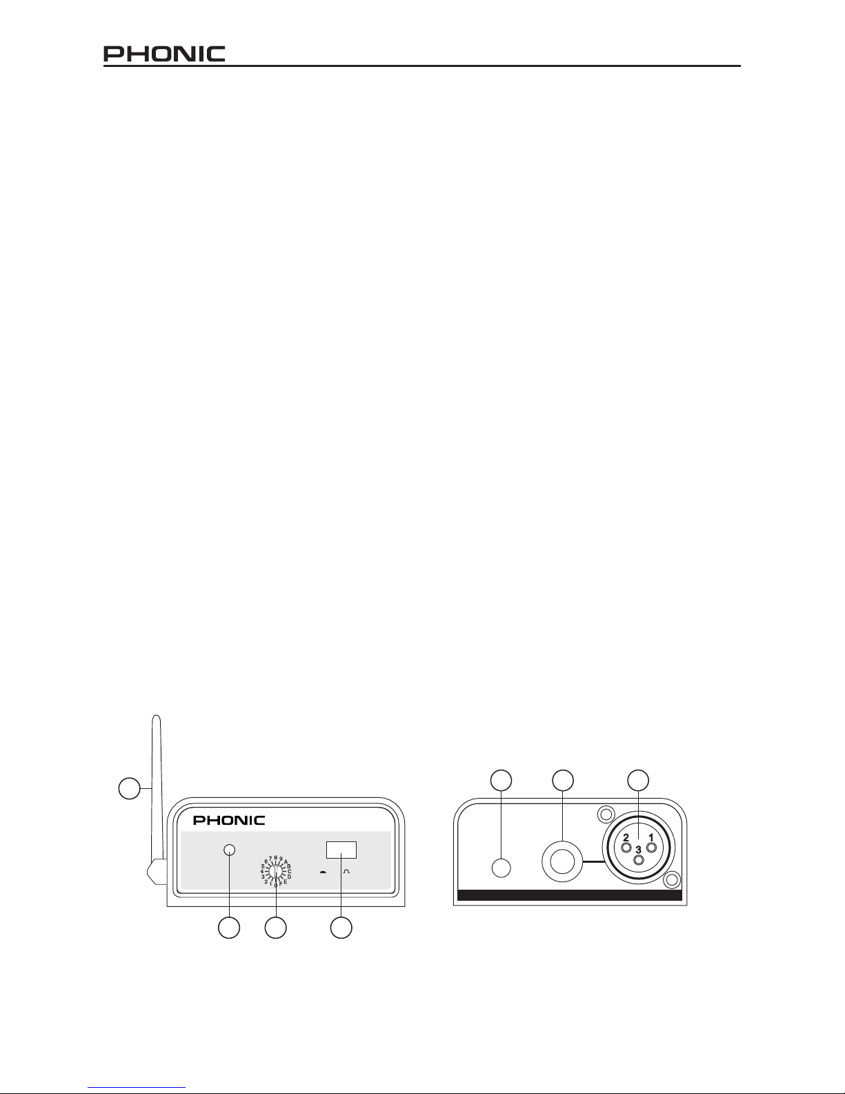
WM70 TRANSMITTER
Front Panel
1. Left and Right Sig/Clip Indicators
–the LED indicator will light up green
when a signal is being received by
the WM70 transmitter. It will change
to red when the signal level becomes
excessive, just 4dB before clipping.
2. Trim Control – these controls adjust
the level of the signal received via
the Combo inputs on the rear that
will be sent wirelessly.
3. Channel Selector – adjusting this
dial to one of the preset channels
allows the WM70 to know which
frequency to send the wireless in-
formation at. Each preset channel
will transmit both the left and right
signals, so that the WM40-L and
WM40-R wireless receivers (if set to
the identical channel) will receive the
signal successfully.
4. Stereo/Mono Selector – This will
allow users to change the wireless
signal sent from the WM70 to be al-
ternated between a mono and stereo
signal.
5. On/Off Button – this button turns
the WM70 on and off. An LED will il-
luminate under this button when it is
on.
Rear Panel
6. Left and Right Combo Input – this
jack accepts both balanced and un-
balanced 1/4” and XLR inputs from
line-level sources (such as the main
output of a mixer).
7. Left and Right Antennas – this for
the insertion of the WM70’s left and
right antennas. Insert the antennas
and adjust them to sit in a vertical
position when the device is in use.
Screw the antenna in to lock it into
place.
8. DC In – plug DC end of the supplied
DC power adaptor into this jack, and
the other end into a suitable AC pow-
er source to allow the WM70 to be
powered.

10 WM SERIES
WM40-L AND WM40-R
RECEIVERS
Insert the wireless receivers into the Ac-
tive Performer Speakers to allow them
to receive signals sent by the wireless
transmitters. These modules should be
inserted and xed into the right hand side
(when facing the rear of the speaker)
compartment at the top of the speaker,
and screwed into place with an M3x4
screw.
1. Channel Selector – adjusting this
dial to one of the preset channels
allows the WM40 to know which
frequency to look for the wireless in-
formation. The wireless transmitter
should be set to the identical chan-
nel if transmission is to occur suc-
cessfully.
2. On Indicator – this LED indicator il-
luminates when the WM40 Receiver
is powered.
3. Antenna – The wireless receiver’s
antenna comes in the form of 2 small
wires protruding from the casing.
When you insert the module into the
appropriate slot on the Performer
speaker, it is best to sticky-tape the
antennas to either side of the com-
partment wall.
IMPORTANT
Whenever using the WM40L or WM40R,
the included short pin should be inserted
into the unused wireless microphone
module slot to enable the wireless mod-
ule to be used.
INSTALLING THE WM40-L
AND WM40-R IN THE PER-
FORMER SPEAKERS
1. Unscrew the module cover (on the
top-right, while facing the rear of the
speaker) on the Performer speaker.
2. Slide the WM40 module into the sock-
et.
3. Use the provided screw to fasten
the WM40 module to the Performer
speaker.
4. Use sticky
–
tape to attach the 2 an-
tenna wires to the rear-inner wall of
the module slot, ensuring they do not
cross one another. This will allow for
greater quality of reception.
5. Replace the module cover.
1 2
3

11
WM SERIES
SPECIFICATIONS
WM60
Type : Single Channel Transmitter
RF Frequency : 614 ~ 870 MHz
Oscillation Type : PLL
Preset Channels : 16 Channels
Frequency Response : 50 Hz ~ 18 kHz ±3dB
Bandwidth : 24 MHz
Stability : ± 0.005%
Frequency Deviation : ± 40 kHz
LED Indicators : Power On/Off, Sig/Clip
Power : External Adaptor, 12 VDC
Output Power : <50 mW
WM70
Type : Dual Channel Transmitter
RF Frequency : 614 ~ 870 MHz
Oscillation Type : PLL
Preset Channels : 16 Channels (stereo)
Frequency Response : 50 Hz ~ 18 kHz ±3dB
Bandwidth : 24 MHz
Stability : ± 0.005%
Frequency Deviation : ± 40 kHz
LED Indicators : Power On/Off, Sig/Clip
Power : External Adaptor, 12 VDC
Output Power : <50 mW
WM40-L and WM40-R
Type : Single Channel Receiver
Preset Channels : 16 Channels
RF Frequency : 614 ~ 870 MHz
Frequency Stability : ±0.005%
S/N Ratio : >100 dB
RF Sensitivity : -100 dBm
Image Rejection : 75 dB
T.H.D. : <0.5% @ 1 kHz
LED Indicator : Power On
AF Output Impedance : 600Ω Unbalanced
Squelch : Pilot Tone & Noise Mute
Operation Voltage : 6 ~ 8 VDC, 500 mA

12 WM SERIES
Table of contents
Other Phonic Transmitter manuals


