Teletek electronics TP2000 User manual
TP2000 TRANSMITTER
and
PALM Programmer
Installation and Operation
Manual
This manual is intended for authorized personnel installing
TP2000 transmitters on perimeters. It does not refer to the
end user of the unit.

GUARANTEE
During the guarantee period the manufacturer shall, at its sole discretion, replace or repair any
defective product when it is returned to the factory. All parts replaced and/or repaired shall be
covered for the remainder of the original guarantee, or for ninety (90) days, whichever period is
longer. The original purchaser shall immediately send manufacturer a written notice of the defective
parts or workmanship, which written notice must in all cases be received prior to expiry of the
guarantee.
INTERNATIONAL GUARANTEE
Foreign customers shall enjoy the same guarantee rights as those enjoyed by any customer in
Bulgaria, except that manufacturer shall not be liable for any related customs duties, taxes or VAT,
which may be payable.
GUARANTEE PROCEDURE
This guarantee will be granted when the appliance in question is returned. The manufacturer shall
accept no product whatsoever, of which no prior notice has been received.
CONDITIONS FOR WAIVING THE GUARANTEE
This guarantee shall apply to defects in products resulting only from improper materials or
workmanship, related to its normal use. It shall not cover:
§ Damages resulting from improper transportation and handling;
§ Damages caused by natural calamities, such as re, oods, storms, earthquakes or lightning;
§ Damages caused by incorrect voltage, accidental breakage or water; beyond the control of the
manufacturer;
§ Damages caused by unauthorized system incorporation, changes, modications or surrounding
objects;
§ Damages caused by peripheral appliances unless such peripheral appliances have been supplied
by the manufacturer;
§ Defects caused by inappropriate surrounding of installed products;
§ Damages caused by failure to use the product for its normal purpose;
§ Damages caused by improper maintenance;
§ Damages resulting from any other cause, bad maintenance or product misuse.
In the case of a reasonable number of unsuccessful attempts to repair the product, covered by
this guarantee, the manufacturer’s liability shall be limited to the replacement of the product as the
sole compensation for breach of the guarantee. Under no circumstances shall the manufacturer be
liable for any special, accidental or consequential damages, on the grounds of breach of guarantee,
breach of agreement, negligence, or any other legal notion.
WAIVER
This Guarantee shall contain the entire guarantee and shall be prevailing over any and all other
guarantees, explicit or implicit (including any implicit guarantees on behalf of the dealer, or
adaptability to specic purposes), and over any other responsibilities or liabilities on behalf of the
manufacturer. The manufacturer does neither agree, nor empower, any person, acting on his own
behalf, to modify or alter this Guarantee, nor to replace it with another guarantee, or another liability
with regard to this product.
UNWARRANTED SERVICES
The manufacturer shall repair or replace unwarranted products, which have been returned to its
factory, at its sole discretion under the conditions below. The manufacturer shall accept no products
for which no prior notice has been received.
The products, which the manufacturer deems repairable, will be repaired and returned. The
manufacturer has prepared a price list and those products, which can be repaired, shall be paid for
every repaired appliance.
The closest equivalent product, available at the time, shall replace the products manufacturer
deems irreparable. The current market price shall be charged for every replaced product.

TABLE OF CONTENTS
I. TP2000 Transmitter
INTRODUCTION .........................................................................................................4
1. GENERAL DESCRIPTION OF TP2000 V.7.X TRANSMITTER ...............................4
1.1 Calculating the Length of the TP2000 Transmitter Antenna...................................5
1.2 Installing TP2000 Transmitter.................................................................................5
1.3 Added Functions in the Software Revision 7.X of TP2000 Transmitter ..................6
2. INTRODUCTION TO TP2000 INTEGRATOR ..........................................................6
2.1 Transmitter Programming Procedures....................................................................7
2.2 Main Screen of Programming Kit for TP2001 v.6.5 Transmitters ...........................7
2.2.1 Bar Menu.............................................................................................................8
2.2.2 Radio Tab ............................................................................................................9
2.2.2.1 Frequency Group..............................................................................................9
2.2.2.2 Identication Group ..........................................................................................10
2.2.2.3 Radio Control Group.........................................................................................10
2.2.2.4 Deviation Field..................................................................................................12
2.2.2.5 Automatic time delay in transmitting an event for mains power supply lost......12
2.2.3 Inputs Tab ............................................................................................................13
2.2.3.1 Advanced Properties Screen ............................................................................15
2.2.3.2 Serial connection with CA60Plus alarm system for transmitting of zone
information....................................................................................................................17
2.2.4 Test Mode Tab .....................................................................................................19
2.2.5 COM Tab .............................................................................................................21
2.2.6 Status Bar............................................................................................................22
2.2.7 Value Verication .................................................................................................22
II. PALM Programmer
1. Introduction to the PALM PROGRAMMER for TP2000............................................24
2. Transmitter Programming Operations ......................................................................25
3. MAIN PROGRAMME SCREEN................................................................................25
3.1 “Load/Save” Button................................................................................................26
3.2 “Get Parameters” Button .......................................................................................26
3.3 “Program” Button...................................................................................................26
4. “Freq&Identify” Screen............................................................................................26
5. “Radio Control” Screen...........................................................................................28
6. “Inputs” Screen........................................................................................................29
7. “Misc Inputs” Screen...............................................................................................30
8. “Advanced 1” Screen...............................................................................................31
9. “Advanced 2” Screen...............................................................................................32
10. Permissible Intervals for the Parameter Values......................................................34
11. Troubleshooting ......................................................................................................34

4 TP2000 Transmitter - Installation and Operation Manual
I. TP2000 Transmitter
Introduction
Thank you for purchasing TP2000 V.7.X transmitter. This new version features the
following additions and improvements:
• It allows for an independent distribution of events between two transmission
frequencies and a specication of a high-priority channel;
• Fully programmable without jumpers, programmed by means of a Windows® based
application with intuitive user-friendly interface;
• Supports a choice of three protocols at the same time - Electronics Line, LARS and
LARS1;
• Superbly reliable performance within a temperature range of - 40°C to + 60°C;
• Compact design.
1. General Description of TP2000 V.7.X Transmitter
TP2000 V.7.X Transmitter consists of a printed circuit board placed in a metal box. It
comprises two modules - a digital one, located in the lower part of the printed circuit
board, and a high-frequency module in its upper portion. The unit is to be found in 3
frequency ranges - 150 MHz, 300 MHz and 450 MHz. Consecutive frequency channels
are 12.5 KHz apart.
Input signals are located in the digital module of the unit and are emitted by the radio-
transmitter. The signal which is sent out is received by a receiver tuned in the same
frequency and is decoded by a central station of the IGP8000, CDS1000, LRS2000 or
LRR8000 type.
The unit has 12 inputs. Two of them are power supply inputs and the others are
information inputs. Their terminals can be connected to a 1.5 sq. mm. conductor.
PC
CONNECTION
+12V OP /
CL AC
TP2000
RADIOENCODER/TRANSMITTER
RESET
BUTTON
TEST
BUTTON
STAT US
LED
SERVICE BY QUALIFIED
PERSONNELONLY!
Programming coupling.
Buttonfor sending out
atestsignal.
RESET Button.
Twocolor status LED.
Input for power supply control;
To be connectedtothe secondarycoil
of theACtransformer.
Inputs
Power supply
12V
OPEN/CLOSE
Signal Input
GNDIN1IN2 IN3IN4IN5IN6 IN7IN8
Figure 1.
General view of
TP2000 Transmitter

TP2000 Transmitter - Installation and Operation Manual 5
The two-colour LED indication is to be understood as having the following meaning
arranged by priority:
• LED has gone out - trouble;
• LED glows in red - transmission in progress;
• LED blinks, alternating between red and green - technical fault (power failure or low
battery charge);
• LED ashes in green - the unit is working properly;
• LED glows in green and ashes in yellow - the unit is in test mode.
• LED glows in yellow - RF fault (bad antenna)
1.1 Calculating the Length of the TP2000 Transmitter Antenna According
to Transmission Frequency
Calculations are made by using the following formula:
L (cm) = 6930 / F (MHz)
Examples:
For F = 161,125 MHz the antenna’s length is calculated as follows:
L = 6930 / 161,125 = 43 cm
For F = 433,125 MHz the antenna’s length is calculated as follows:
L = 6930 / 433,125 = 16 cm
After calculating the exact length required the antenna is to be cut.
The length of the antenna is to be measured from its base, where it emerges from the
coupling.
1.2 Installing TP2000 Transmitter
The installation of the transmitter starts with its mounting in an appropriate position on
the site. It is preferable to remove the cover rst and take into consideration whether it
will be possible to attach the xing screws after installation has been completed. The unit
should be mounted where it will have good conditions for transmitting, e.g. far from metal
screens. Provide for at least 50 cm above the unit for the antenna that you can connect
as soon as the case has been xed in place.
Each transmitter comes with settings programmed by the manufacturer. Programming it
involves changing their conguration and saving new parameters.
Thus the unit is customized for a particular site.
To program the unit with a PC you will need:
• IBM compatible PC, WINDOWS NT/95/98/2000/XP;
• TP2000 Integrator program;
• a PS2-to-RS cable.
You need to have installed the TP2000 Integrator program on your computer. To do
this you have to run the SETUP command from the oppy disc you have been provided
with by the vendor. On the successful completion of installation the icon of TP2000
Integrator will appear in your Program Folder.
6 TP2000 Transmitter - Installation and Operation Manual
1. 3 Added Functions in the Software Revision 7.X of TP2000 Transmitter
In the Software Revision 7.X of TP2000 Transmitter are added the following functions:
1. Serial connection with CA60Plus alarm system for transmitting of zone
information.
2. Time delay in transmitting an event for mains power supply lost.
3. A possibility for directing of input events independently to both frequencies.
4. RNA algorithm for signal transmitting at presence of non-inverted restore
input.
The added functions cause a change of the TP2000 transmitter parameters programming
software - TP2000 Integrator. The button Advanced Properties is moved in the screen
Inputs, see page 13. The other changes in the TP2000 Integrator software are explained
together with the added functions of the TP2000 Transmitter.
2. Introduction to TP2000 Integrator
TP2000 Integrator is a ancillary program that is part of the transmitter programming
suite for the TP2000, TP2001 and TP2000 V.6.X / V.7.x transmitters.
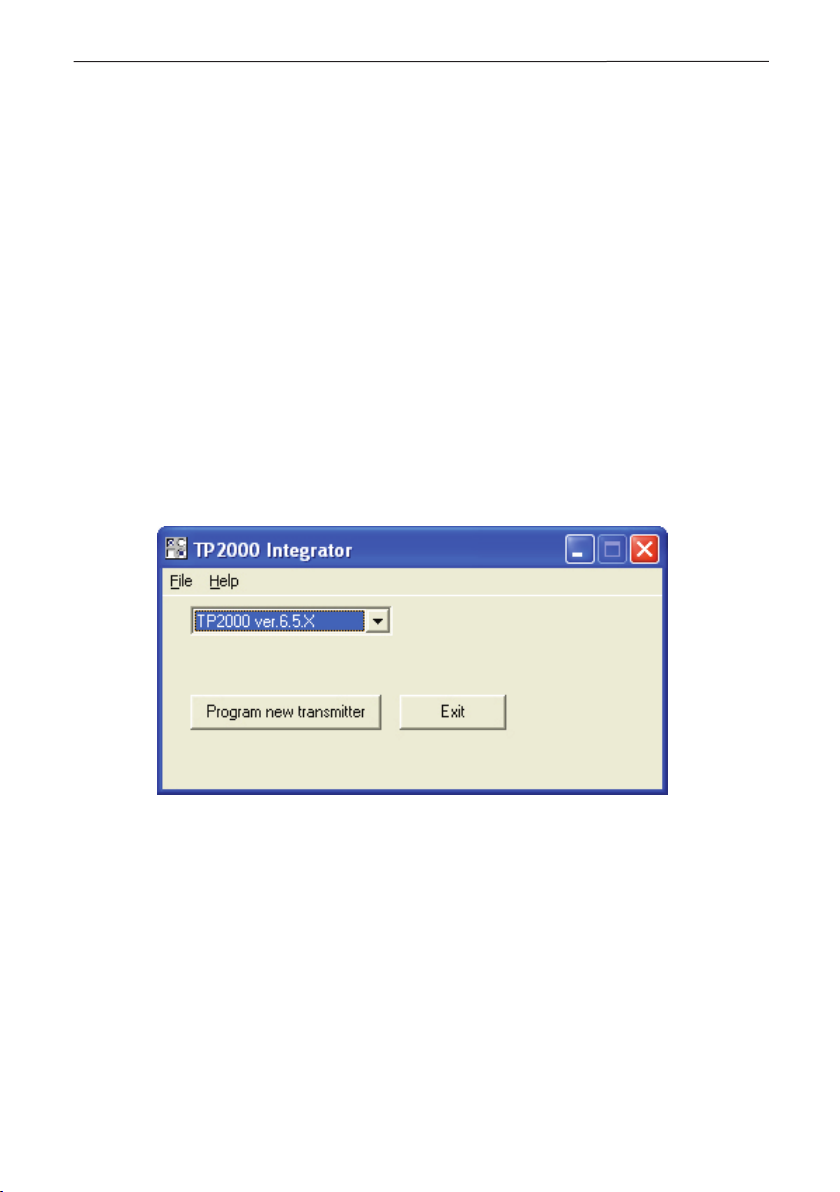
Start the program by double-clicking the left button of the mouse on its icon.
Figure 2. TP2000 Integrator Starting Screen
The menu of the program holds a File and Help options.
The drop-down File accesses the following commands:
• New - create a new le;
• Open Default - open an existing le with transmitter settings;
• Exit - closes the application.
The Help opens a le with help topics.
TP2000 Transmitter - Installation and Operation Manual 7
2.1 Transmitter Programming Procedures
1. In the combo-box press and select one of the options available - TP 2000, TP
2001, TP 2000 ver.6.X or TP2000 ver.6.5.X.
2. To interrupt transmitter programming procedures and close the application window
press button .
3. To conrm your selection and proceed to program the transmitter press button
.
To program a transmitter with settings specied in an existing le, select the Open
Default command from the Bar Menu. Open the required le and press the Program
XXX button.
Choose TP2000 ver.6.5.X and this will invoke the Programming Kit for TP2001
v.6.5 Transmitters program which will enable you to store the required settings in the
transmitter.
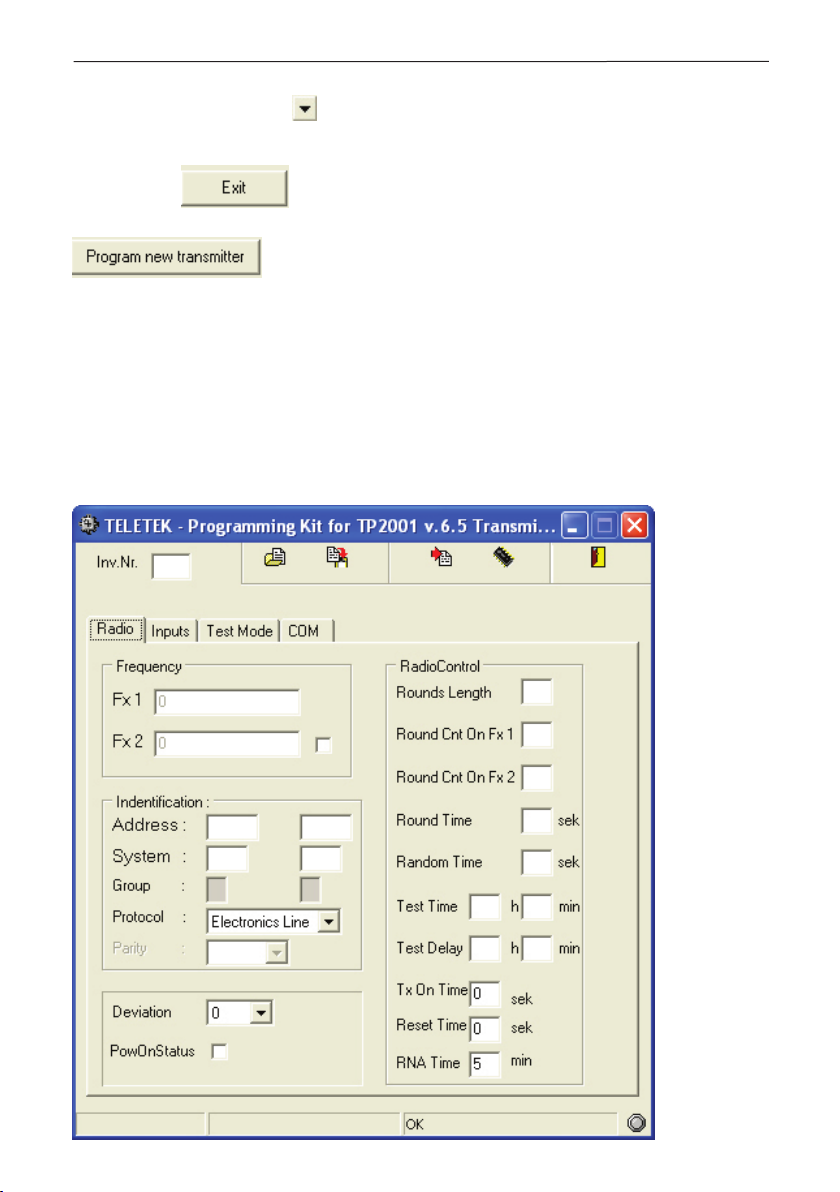
2.2 Main Screen of Programming Kit for TP2001 v.6.5 Transmitters
The main screen of Programming Kit for TP2001 v.6.5 Transmitters program is shown
on the Figure 3.
Figure 3.
Main Screen
8 TP2000 Transmitter - Installation and Operation Manual
In the main screen of Programming Kit for TP2001 v.6.5 Transmitters program are to
be found:
• Bar Menu with commands for uploading data from a transmitter or a le, storing settings
in a transmitter or in a le, accessing a le with instructions on using the program and
exiting the application;
• Radio tab that controls the radio control parameters and species the unit’s identity in
the perimeter;
• Inputs tab for setting up the unit inputs;
• Test Mode tab for testing the new transmitter settings;
• COM tab for specifying the COM port via which the transmitter is connected to the
personal computer;
• Status Bar.
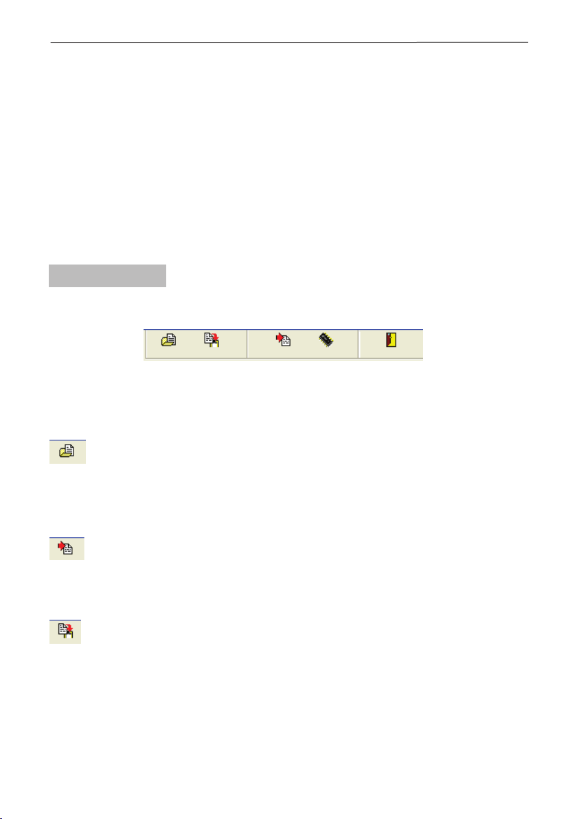
2.2.1 Bar Menu
The Bar Menu is the row of buttons below the title bar in the window of Programming
Kit for TP2001 v.6.5 Transmitters, see Figure 4.
Figure 4. The Bar Menu
The Bar Menu of Programming Kit for TP2001 v.6.5 Transmitters accesses the
following commands:
Open Default Button
Press this button to open an existing le with parameters for setting up a transmitter.
Thus you will dispense with the necessity of having to type manually the setting of each
eld. This makes programming much easier for you when you have to set up transmitters
on similar perimeters.
Write Default Button
After specifying all settings press this button to create a new le with parameters for
programming a transmitter. This button also allows you to save the changes you have
made to an existing le in a le of a different name.
Read from Transmitter Button
Pressing this button will cause the program to upload the setting of a transmitter.
In order to accomplish this successfully you rst have to do the following:
• Connect the unit to your PC using the PS2-to-RS cable you have been provided with;
• In the COM tab specify the port of your PC to which the unit is connected;
• Power up the unit.
TP2000 Transmitter - Installation and Operation Manual 9
Write to Transmitter Button
Stores the settings in the transmitter. In order to do this the transmitter has to be
connected to the PC and supplied with power.
Exit Button
Before pressing this button make sure you have stored the modications you have made
by selecting the Write to Transmitter command.
Note: If you are using Programming Kit for TP2000 V.6.X Transmitter you will nd and
a Help button in the bar menu.
Help Button
Opens a le with instructions about using the program.
The Inventory Number eld is situated in the upper left corner of the main screen.
Inventory numbers are set up at the time of manufacture and is uploaded from the unit
on selecting the Read from Transmitter command.
2.2.2 Radio Tab
Below the Bar Menu are to be found four tabs that control the basic settings of the unit:
Radio, Inputs, Test Mode and COM.
The rst tab you can select from the main screen is Radio - the general view of the
Radio tab is shown on Figure 3.
There are three eld groups in this tab:
• Frequency;
• Identication;
• RadioControl, as well as a button that calls up an additional settings Advanced
screen.
• Deviation.
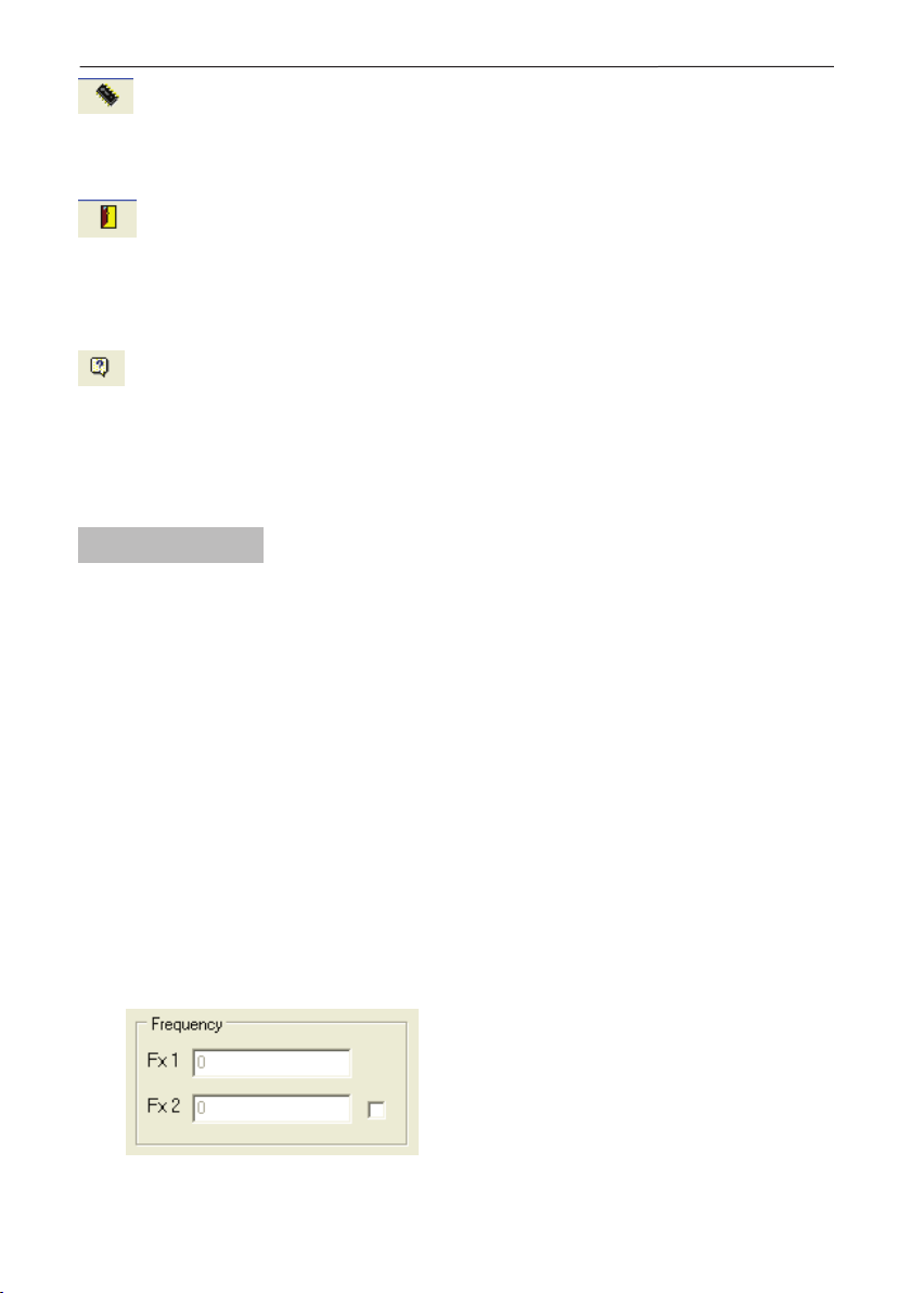
2.2.2.1 Frequency Group
The Frequency eld group, see Figure 5, contains two elds with the transmitter’s
transmission frequencies that have been set at the time of manufacture. No corrections
are allowed in these elds.
In this group of the Radio screen you can check what are the frequency settings of your
transmitter.
Figure 5.
The Frequency Field.
Note that in the Fx1 and Fx2 elds will be
set transmission frequencies at the time
of manufacture.

10 TP2000 Transmitter - Installation and Operation Manual
2.2.2.2 Identication Group
In the Identication eld group, see Figure 6, you set up the identity of the transmitter
within the perimeter.
Figure 6.
The Identication group.
The Address, System and Group elds set up the parameters by which the transmitter
is to be identied. The range of the possible values of each eld will vary in accordance
with the protocol that you have selected.
Note: Two values can be set up on each of the above mentioned elds. This can be
useful when one transmitter is shared by two separate sites.
TP2001 v.6.5 Transmitter supports three protocols: Electronics Line, LARS and LARS1.
In the Protocol eld press and highlight the name of the protocol your system
requires.
In the Parity eld press and highlight one of the options available in accordance with
the central station:
• NONE;
• ODD;
• EVEN.
Some of the elds will only be available when using a particular protocol. Thus the Group
and Parity elds will not be active if you have selected the Electronics Line protocol. If a
eld is inactive you will not be allowed to type a value in it.
When you modify a setting make sure the new value is within the permitted range.
Otherwise an error message will be displayed.
2.2.2.3 Radio Control Group
In this group you can set up the radio control parameters, see Figure 7.
• In the Rounds Length eld type the number of required repetition of events in a round.
Type a value from 1 to 15.
• In the Round Count on Freq 1 eld specify the number of repetition of a round on
frequency 1. Type a value from 1 to 15.
• The Round Count on Freq 2 eld species the number of repetition of a round on
frequency 2. Type a value from 1 to 15.
• In the Round Time eld set up the interval between the rounds. It can vary from 0 to
127 seconds.

TP2000 Transmitter - Installation and Operation Manual 11
• In the Random Time eld type a random time component in the range from 0 to 127
seconds. This value will be added to that of the Round Time eld, and the sum total will
determine the interval between two consecutive rounds.
• In the Test Time eld specify a time interval for test messages.
• In the Test Delay eld type a value for the random time component for test messages.
• In the Tx On Time eld specify a time interval for establishing a stable carrier frequency
before starting transmission.
• In the Reset Time eld specify a time interval for resetting the transmitter after power
has been supplied after which transmission will begin.
Figure 7.
Radio Control Group.
Note:
When you modify a setting make sure the new
value is within the permitted range. Otherwise
an error message will be displayed.
• RNA Time eld specify an RNA Algorithm for signal transmitting at presence of non-
restored input.
The algorithm RNA (Repeat Non-restored Alarms) solves the problem, when there is a
permanent fault in the wiring at the transmitter input. That kind of trouble could be caused
of control device fault (PGM fault) or in case of cutting the cables to the transmitter.
In case of trouble like this, the transmitter will automatically start transmitting the message
Trouble for the relevant input. The RNA Time for automatic repeating of the trouble
message is programmed in the interval from 5 to 60 minutes. The RNA Time period is
specied in the Radio tab in the Radio Control screen, Figure 7.
In addition you can program at which transmitter inputs the RNA algorithm will be active.
That could be specied in the Advanced Properties screen, see Figure 11, page 15.
The transmitting can be stopped from the installer – with restoring of the signal at the
transmitter input or after manual pressing of the Test button on the TP2000.

12 TP2000 Transmitter - Installation and Operation Manual
2.2.2.4 Deviation Field
The Deviation eld, see Figure 8, has to correspond to the central station settings.
Press and select one of the options available in the combo-box. 0, 1, 2, 3, 4, 5, 6 or
7. Each step corresponds to 500 Hz.
A check in the PowerOnStatus box indicates that on powering the transmitter will feed
back information on the status of each of its inputs.
Figure 8. The Deviation Field.
When you modify a setting make sure the new value is within the permitted range.
Otherwise an error message will be displayed.
2.2.2.5 Automatic time delay in transmitting an event for mains power supply lost
This function solves the problem when there is power supply failure in a residential
district and all transmitters try at the same time to transmit a Trouble message in the
monitoring station.
The time delay is specied in seconds and is in arithmetic relationship of the monitored
object number - the object number is specied by the installer and is introduced in the
Address eld (see Figure 3, on page 7).
The time delay Tdelay in transmitting an event for mains power supply lost is calculated
by the formula:
Tdelay = NN * 1.5 [sec],
where
• NN are the last two digits of the object number XXNN (specied by the installer).
The maximum value of the time delay is 150 seconds, and the minimum – 0 seconds.
If there is another event (i.e. Alarm event) meanwhile, it will be transmitted immediately.
Example: Let the object number is 2315. Then the time delay will be:
Tdelay = 15 * 1.5 [sec] = 22.6 [sec].

TP2000 Transmitter - Installation and Operation Manual 13
2.2.3 Inputs Tab
Next to the Radio tab you will nd the Inputs tab, see Figure 9, that controls the values
on the transmitter’s inputs.
Figure 9. The Inputs Tab.
Dening the parameters on the Transmitter inputs.
In the Inputs eld dene the parameters on the transmitter inputs - from In1 to In8, the
Arm (Open/Close) and AC (power on) inputs.
The events for which you can require activation, i.e. a signal to be send out, are:
• AL - the transmitter will send out a signal for an alarm event as soon as a signal is
received on the corresponding input.
• RE - the transmitter will send out a restore signal on receiving a signal on the
corresponding input.
• TR - the transmitter will send out a signal if a fault is registered at the corresponding
input.
• INV - the transmitter will invert alarm and restore signals.

14 TP2000 Transmitter - Installation and Operation Manual
Colour indication:
• red - inactive;
• green - active;
• grey - status impossible.
To change an event status left-click an indicator.
Placing the cursor of the mouse on the soft button of an input allows visualization of
its connection scheme in the lower left corner of the window. Next to the scheme the
number of the corresponding input will be displayed.
The soft button can be xed on a particular input by left-clicking the mouse on it. Thus you
will be allowed to set up the status on the other inputs, while the scheme of connection of
the selected input is visualized throughout the process.
In the Address and Channel elds you can set up the connection between the physical
channel and the logical channels for signal transmission.
The Address eld species the address to which the corresponding input is linked.
The Channel eld holds the logical input to be sent.
Let us assume that four of the transmitter inputs correspond to the rst site and the other
4 - to the second one. Dene one of the inputs on the second site as Arm, i.e. Open/
Close and the other three as Channel1, Channel2, Channel3.
Governing Circuit Scheme
Figure 10. Governing Circuit Schemes.
IN IN
IN
+12V
IN
+12V
IN
EOL
R=2,2K
IN
EOL
R=2,2K
IN
EOL
R=2,2K
IN
IN
+12V
IN
EOL
R=2,2K
IN
IN
+12V
IN
EOL
R=2,2K
Pull up
Pull
Down
Balance
Resistor
Non-Inverted Inverted
ALARM ALARMRESTORE RESTORETROUBLE
TP2000 Transmitter - Installation and Operation Manual 15
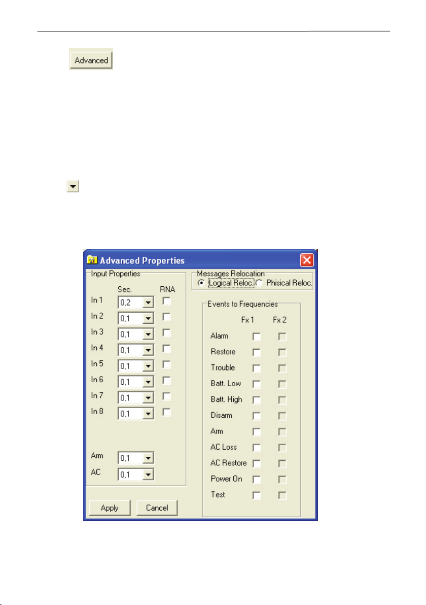
2.2.3.1 Advanced Properties Screen
Press button in the Inputs tab to access the additional ne settings
Advanced Properties screen, see Figures 11 and 12.
The Advanced Properties screen is divided into three groups of elds:
• Input Properties
• Messages relocation – contains two elds: Logical Reloc. and Physical Reloc.
• Radio control settings – two screens are possible: Events to Frequencies (when eld
Logical Reloc. has been chosen, Figure 11) and Inputs to Frequencies (when eld
Physical Reloc. has been chosen, Figure 12).
In the Input Properties group specify the sensitivity of each input of the transmitter.
Press and highlight one of the options available - 0,1; 0,2; 0,5; 1; 2; 5; 10 or 20
seconds.
Sensitivity determines the time of stimulation before an event signal is sent out.
The Message Relocation group allows for a distribution of events between the two
transmission frequencies.
Figure 11. Advanced Properties Screen.
Events to Frequencies active eld.

16 TP2000 Transmitter - Installation and Operation Manual
With choosing the Logical Reloc. you can direct the events to one of the two frequencies
as desired.
The type of the events that you can direct to a relevant frequency are as follows:
• Alarm (alarm event in the system)
• Restore (Restore the security monitoring of the system)
• Trouble (Technical trouble in the system)
• Batt. Low (Low charge level of the battery)
• Batt. High (Restore of the normal charge level of the battery)
• Disarm (Disarming the system)
• Arm (Arming the system)
• AC Loss (Main power supply loss)
• AC Restore (Main power supply recovery)
• Power On (Power supply on)
• Test (The system is in test mode)
Check one or both boxes next to each event depending on whether you want the signal
for this event to be transmitted on Frequency 1, Frequency 2 or on both frequencies at
the same time.
With choosing the Physical Reloc. you have the possibility to direct the input events
independently to both frequencies, see Figure 12.
Figure 12. Advanced Properties Screen.
Inputs to Frequencies active eld.

TP2000 Transmitter - Installation and Operation Manual 17
With choosing the Physical Reloc. combo-box you can program transmitting of input
messages to a relevant frequency - Frequency 1, Frequency 2 or to both of them.
The numbers of the inputs are situated vertically. The frequencies are situated horizontally
thus are specied two columns – for Frequency 1 and Frequency 2. A mark in the
combo-box next to the relevant input means that the messages will be transmitted by
the relevant frequency (frequencies). It is possible the input messages to be transmitted
by Frequency 1, Frequency 2 to the both of them. The priority of the frequencies in the
transmitting is automatically determined.
If you wish to use one transmitter for two sites you can specify their addresses in the
Address1 and Address 2 elds and set up a link with the corresponding logical channels
for each of them.
After modifying the values on the elds press button for the changes
to be updated, or button to discard them and keep the old settings.
Note: In order to be able to choose between the two frequencies you rst have to check
in the box of the Fx2 (Enabling of Frequency 2) in the Radio tab, Frequency eld.
Otherwise the elds in the column of Frequency 2 will not be available, see Figure 13.
Figure 13.
Enabling of Frequency 2.
2.2.3.2 Serial connection with CA60Plus
alarm system for transmitting of zone information
Connect the green interface cable of the CA60Plus control panel to the AC input of the
TP2000 Transmitter. Thus you will make a serial connection between them – see also
Figure 14.
Figure 14.
Serial
connection
between
CA60Plus
Control
Panel and
TP2000
Transmitter.

18 TP2000 Transmitter - Installation and Operation Manual
The establishing of serial connection between TP2000 Transmitter and CA60Plus
Control panel is automatic after you power up the transmitter or single pressing of the
RESET button of TP2000. You must also check the eld CA62 Serial Connection in the
Inputs screen, see Figure 15.
The system status – armed or disarmed – is automatically transmitted as Arm/Disarm.
The panel zone alarms are automatically transmitted as input alarms respectively from
1 to 6.
Figure 15. Serial connection between
Enabling a serial connection between CA60Plus and TP2000.

TP2000 Transmitter - Installation and Operation Manual 19
At the inputs 7 and 8 can be programmed additional events for transmitting.
You can choose among the following events:
• Fuse - blown out fuse in the СА60Plus control panel.
• Line Error - Telephone line missing.
• Communicator Error - error in attempt for transmitting a telephone message.
• Siren - activated sounder in the conguration of CA60Plus control panel.
• PGM1 - duplicates the state of output PGM1 of СА60Plus control panel.
The messages for loss or recovery of main power supply and these for the battery
status are automatically generated and transmitted of the TP2000 Transmitter.
A Trouble message will be automatically transmitted to the monitoring station if the serial
connection between TP2000 and CA60Plus has been interrupted.
At using a serial connection with Ca60Plus control panel the physical inputs of the
TP2000 Transmitter have not been scanned.
Time delay in transmitting an event AC (mains power supply lost)
If one transmitter is to be used for two sites, the sites can respectively be set the values
of Addr 1 and Addr 2 and for each one a connection can be established with the
respective logical channels.
2.2.4 Test Mode Tab
Third in the main screen comes the Test Mode tab, see Figure 16. As desired you
can select Test Mode after the programming process of the transmitter has been
completed.
To run the program in this mode the transmitter has to be correctly powered. A personal
computer will play the part of a central station that receives the signals.
A table will be displayed on the screen with details on the status of each of the inputs of
the transmitter.
If two sites share one transmitter two columns with indicators will be displayed with the
number of the corresponding site designated above the indicators that refer to it.
The rst indicator in the column stands for the OPEN/CLOSE input.
Following it come the eight inputs dened as logical channels Ch1 - Ch8.
Below them are to be found the indicators:
• Test - stands for a test signal;
• Battery - battery status;
• AC - power supply;
• Power - power on. This indicator will light up only if there is a check in the PowOnStatus
box of the Radio tab.
For each of the 8 inputs indicators the light legend is as follows:
• Alarm (red) stands for activation;
• Restore (light green) means normal status is restored;
• Trouble (yellow) stands for a technical fault.

20 TP2000 Transmitter - Installation and Operation Manual
Figure 16. The Test Mode Tab.
At rst all indicators will glow in dark green. This means that the inputs are inactive, i.e.
no signal has been sent out.
The colour indication of the last four indicators is to be understood as follows:
• Test lights up in light green on sending a test message.
• Battery glows in red when the battery is at and in green when the charge has been
restored.
• AC glows in light green when power has been fed from the mains and in red when
power failure has been established.
• Power lights up in light green when power up the transmitter.
Note: If within 30 seconds no input signal has been received the program Programming
Kit for TP2001 v.6.5 Transmitters will automatically quit test mode.
Table of contents


