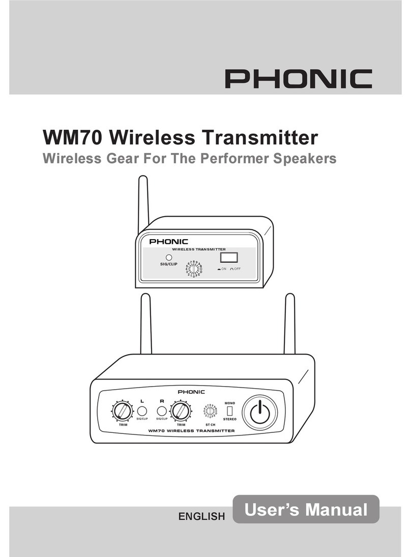
Phonic WM60 User manual

1
WM60 / WM70
WM60 / WM70
Wireless Transmitters
ENGLISH
User’s Manual
OFFON
SIG/CLIP
WIRELESS T RANSMITTER
WM60

2WM60 / WM70

3
WM60 / WM70
WM60 / WM70
Wireless Transmitters
CONTENTS
Phonic reserves the right to improve or alter any information suppied within this document without prior notice.
V1.1 OCT 17, 2006
INTRODUCTION....................................................................................................... 4
FEATURES................................................................................................................ 4
WM60 TRANSMITTER ..............................................................................................5
WM70 TRANSMITTER ..............................................................................................6
SPECIFICATIONS......................................................................................................7

4WM60 / WM70
INTRODUCTION
Congratulations on your purchase of ei-
ther the WM60 or WM70 wireless trans-
mitter from Phonic. With either of these
transmitters, and the Phonic WM-40 or
WM-400 receivers, you are on your way
to creating a completely wireless audio
set up. The WM transmitters will provide
you with high quality wireless signals sent
over great distances, though will prove to
be simple to use.
Please have a thorough read of this
user’s manual before operating the WM
modules. Inside this guide you will nd
information on the ease of your wireless
set up, as well as some great trouble-
shooting tips and a complete run-down
on your modules’ features. After reading,
place the manual in an easy to remember
place so that you can come back to it in
future if ever necessary.
FEATURES
Common Features
●
Operates on a UHF band,
614.175~804.800 MHz (FCC)
614.175-864.800 MHz (CE)
●
16 selectable UHF channels preset
●
Internal squelch and mute circuit
mode can resist extraneous noise
WM60 Additional Features
●
Single channel stand-alone transmit-
ter
●
Signal/Clip indicator
●
External power supply
WM70 Additional Features
●
Dual channel stand-alone transmitter
●
Signal/Clip indicator
●
Volume control to set the appropriate
level to avoid clip
●
Mono/Stereo switch for easy setting
in mono or stereo sound system
●
16 preset channel encoder will decide
the left and right channel frequencies
automatically
●
External power supply

5
WM60 / WM70
WM60 TRANSMITTER
Front Panel
1. Sig/Clip Indicator– the LED indi-
cator will light up green when a sig-
nal is being received by the WM60
transmitter. It will turn red when the
signal level becomes excessive, just
4dB before clipping.
2. Channel Selector– adjusting this dial
to one of the preset channels allows
the WM60 to know which frequency
to send the wireless information at.
The wireless receiver should be set
to the identical channel if transmis-
sion is to occur successfully.
3. On/Off Button– this button turns the
WM60 on and off.
4. Antenna– this is the WM60’s an-
tenna. Adjust it so it sits in a vertical
position when the device is in use
(change the position if the wireless
signal quality is poor). Push the an-
tenna in to release it before adjusting
its position.
Rear Panel
5. 1/4” Input– this jack accepts bal-
anced and unbalanced 1/4” inputs
from line-level sources.
6. XLR Input– this jack accepts bal-
anced XLR inputs from line-level
sources. Both the 1/4” jack and the
XLR jack run in parallel.
7. DC In– plug DC end of the supplied
DC power adaptor into this jack, and
the other end into a suitable AC pow-
er source to allow the WM60 to be
powered.
DC IN INPUT
756
OFFON
SIG/CLIP
WIRELESS TRANSMITTER
WM60
2 31
4
For more information on using the WM wireless systems, please consult the WM-SYS1, 2, 3 or 4 manuals.

6WM60 / WM70
WM70 TRANSMITTER
Front Panel
1. Left and Right Sig/Clip Indicators
–the LED indicator will light up green
when a signal is being received by
the WM70 transmitter. It will change
to red when the signal level becomes
excessive, just 4dB before clipping.
2. Trim Control – these controls adjust
the level of the signal received via
the Combo inputs on the rear that will
be sent wirelessly.
3. Channel Selector – adjusting this
dial to one of the preset channels
allows the WM70 to know which
frequency to send the wireless in-
formation at. Each preset channel
will transmit both the left and right
signals, so that the WM40-L (or
WM400-L, WM400D-L) and WM40-
R (or WM400-R, WM400D-R) wire-
less receivers (if set to the identical
channel) will receive the signal suc-
cessfully.
4. Stereo/Mono Selector – This will
allow users to change the wireless
signal sent from the WM70 to be al-
ternated between a mono and stereo
signal.
5. On/Off Button – this button turns the
WM70 on and off. An LED will illumi-
nate under this button when it is on.
Rear Panel
6. Left and Right Combo Input – this
jack accepts both balanced and un-
balanced 1/4” and XLR inputs from
line-level sources (such as the main
output of a mixer).
7. Left and Right Antennas – this for
the insertion of the WM70’s left and
right antennas. Insert the antennas
and adjust them to sit in a vertical
position when the device is in use.
Screw the antenna in to lock it into
place.
8. DC In – plug DC end of the supplied
DC power adaptor into this jack, and
the other end into a suitable AC pow-
er source to allow the WM70 to be
powered.
For more information on using the WM wireless systems, please consult the WM-SYS1, 2, 3 or 4 manuals.

7
WM60 / WM70
SPECIFICATIONS
WM60
Type : Single Channel Transmitter
RF Frequency : 614.175~804.800 MHz (FCC)
614.175-864.800 MHz (CE)
Oscillation Type : PLL
Preset Channels : 16 Channels
Frequency Response : 50 Hz ~ 18 kHz ±3dB
Bandwidth : 24 MHz
Stability : ± 0.005%
Frequency Deviation : ± 40 kHz
LED Indicators : Power On/Off, Sig/Clip
Power : External Adaptor, 12 VDC
Output Power : <50 mW
Overall Dimensions : 98x35x126 mm (2.83” x 1.38” x 4.96”)
Net Weight : 350 g ( 0.77 lbs)
WM70
Type : Dual Channel Transmitter
RF Frequency : 614.175~804.800 MHz (FCC)
614.175-864.800 MHz (CE)
Oscillation Type : PLL
Preset Channels : 16 Channels (stereo)
Frequency Response : 50 Hz ~ 18 kHz ±3dB
Bandwidth : 24 MHz
Stability : ± 0.005%
Frequency Deviation : ± 40 kHz
LED Indicators : Power On/Off, Sig/Clip
Power : External Adaptor, 12 VDC
Output Power : <50 mW
Overall Dimensions : 140 x 43.5 x 179 mm (5.5” x 1.7” x 7”)
Net Weight : 325 g (0.72 lbs)

8WM60 / WM70
6103 Johns Road #7

9
WM60 / WM70
This manual suits for next models
1
Table of contents
Other Phonic Transmitter manuals
Popular Transmitter manuals by other brands

Absolute Process Instruments
Absolute Process Instruments APD 6010 quick start guide

AMG
AMG AMG4681-1550-C instruction manual
logika
logika WL-ZTPCNPB-I020-01 product manual
Sound Associates
Sound Associates SA1401 Operation manual
AMX
AMX TXC32 Schematic diagram
Parallel Audio
Parallel Audio BP6100 Operation manual
