“ASSEMBLE INSTRUCTIONS”
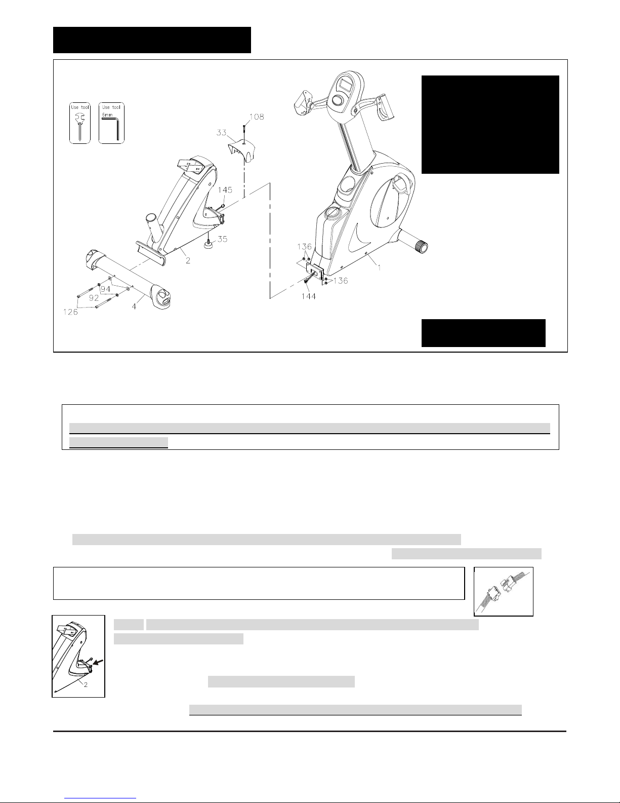
STEP 6 –
Inner Seat Carriage Slider
Assembly
Slide the Inner Seat Carriage Slider (6) into the
Rear Support Frame Assembly (2) with four sets of
Washers (8x16x2.0t)(94), Lock Washers (M8)(92)
and Bolt, Bottom Head (M8xp1.25x20mm)(120).
Do not tighten bolts until Step d. of Step 8.
STEP 7 –
Fixed Bracket for Seat
Rail Assembly
Attach the Fixed Bracket for Seat Rail (71)to the
rear side of the Seat Carriage Assembly (9) and
secure with four sets of Washers (8x16x2.0t)(94),
Lock Washers (M8)(92) and Bolts, Socket Head
(M8xp1.25x16mm)(123) as the figure shows below.
STEP 8–
Seat Carriage Assembly
NOTE: For clear assembly purpose, please notice that Square Stoppers (53), Hex Head Bolt (M8)(113)
and Nuts (M8)(131) have been pre-assembled together as the figure shows on the right
a. The Hole 1 of the Seat Carriage Assembly (9):
Follow the figure on the left, slide Seat Carriage Assembly (9) into the Rail
Pivot (8) and secure one Square Stoppers (53) and one Bolt, Hex Head
(M8xp1.25x115mm)(113) through the Hole 1 of the Seat Carriage Assembly (9)
with one Square Stopper (53) and one Nut (M8xp1.25)(131).
b. The Hole 2 of Seat Carriage Assembly (9):
Then move on to slightly secure one Washer (8x16x2.0t)(94), one Lock
Washer (M8)(92) and one Bolt, Socket Head (M8xp1.25x16mm)(123)through the
Hole 2 of Seat Carriage Assembly (9) with one Washer (8x16x2.0t)(94), one Lock
Washer (M8)(92) and one Bolt, Socket Head (M8xp1.25x16mm)(123).Do not
tighten bolts until Step d.
c. Secure the bottom of the front Seat Carriage Assembly (9) and the bottom of the Rail Pivot (8)
with four sets of Washers (8x16x2.0t)(94),Lock Washers (M8)(92) and Bolts, Socket Head
(M8xp1.25x16mm)(123) as the figure shows on the left. Do not tighten until Step d.
d. Follow the figure on the right to attach the Fixed Bracket for Seat Rail
(71) to the Inner Seat Carriage Slider (6) and tightly secure with one
Bolt, Hex Head (M10xp1.5x90mm)(115) and one Nylock Nut
(M10xp1.5)(138).
Start to tightly secure all the bolts, screws on the front side of the Seat
Carriage Assembly (9). Make sure all bolts and screws related to STEP 6, 7 and 8 are tightened
before moving on to the next page


 Service manual")