Pichler LBE 250 Service manual

Operating and mounting
instructions
Air humidification unit
LBE 250/LBE 500
Systematic ventilation.
COMFORT
VENTILATION
OPERATING AND
MOUNTING INSTRUCTIONS
LBE 250 / LBE 500

Contents
1. Introduction ............................................................................................................................ 4
2. Intended use............................................................................................................................ 4
5.Safety notices .......................................................................................................................... 6
6.Transport, storage and disposal................................................................................................8
6.1 Dimensions and weight ..........................................................................................................................8
6.2 Packaging ............................................................................................................................................... 8
6.3 Storage ................................................................................................................................................... 8
6.4 Check for completeness ..........................................................................................................................8
6.5 Scope of supply ....................................................................................................................................... 8
7.Structure ................................................................................................................................. 9
8.Description of functions......................................................................................................... 10
8.1 Working principle.................................................................................................................................. 10
8.2 Humidity control ...................................................................................................................................10
8.3 Temperature control............................................................................................................................. 11
9.Control system....................................................................................................................... 11
9.1 Operation/keypad/display....................................................................................................................11
9.2 Customer menu.....................................................................................................................................12
9.3 Settings Temperature 21°C< ................................................................................................................12
10.Operational statuses.............................................................................................................. 13
10.1 Automatic activation/deactivation.......................................................................................................13
10.2 Automatic activation/deactivation (Auto STANDBY)............................................................................13
10.3 Manual activation/deactivation (Manu STANDBY) ..............................................................................13
10.4 Automatic activation/deactivation depending on air current ("Control Off")......................................13
10.5 Rinsing ..................................................................................................................................................14
10.6 Control on ............................................................................................................................................. 14
10.7 Fill.......................................................................................................................................................... 14
10.8 Water replacement............................................................................................................................... 14
11.Error messages ...................................................................................................................... 14
11.1 Filter change! (customer)......................................................................................................................14
11.2 UVC pip defective! (expert) .................................................................................................................. 14
11.3 Descaling! (expert)................................................................................................................................ 14
11.4 Pump, outlet defective! (expert)...........................................................................................................15
11.5 Humidity too high! (expert) ..................................................................................................................15
11.6 Humidity too low! (expert)....................................................................................................................15
11.7 Service (expert) .....................................................................................................................................15
3.Liability ................................................................................................................................... 5
4.Warranty ................................................................................................................................. 5
6.6Waste disposal........................................................................................................................................ 8

13.Commissioning................................................................................................................... 16
14.Expert menu ...................................................................................................................... 18
14.1 Expert menu overview ...............................................................................................................................18
14.2 Settings ...................................................................................................................................................... 19
15.Technical data.................................................................................................................... 24
16.Dimensions/design variants ............................................................................................... 25
16.1 LBE 250...................................................................................................................................................... 25
16.2 LBE 500...................................................................................................................................................... 26
17.Mounting ........................................................................................................................... 27
18.Connections/installation.................................................................................................... 28
18.1 Routing of air lines.....................................................................................................................................28
18.2 Waste water connection............................................................................................................................ 28
18.3 Mains water connection ............................................................................................................................29
18.4 Water heater battery connection ..............................................................................................................30
18.5 Hydraulic connection diagram (for version with warm water heater battery):.........................................30
18.6 Low temperature heating (only LBE 250!): ................................................................................................31
19.Wiring diagram .................................................................................................................. 32
20.Maintenance (expert) ........................................................................................................ 33
22.Subject to change without notice ....................................................................................... 35
23.EG-Konformitätserklärung ................................................................................................. 36
21.Spare parts and accessories ................................................................................................ 35
12.Maintenance (customer): "Filter Change" ......................................................................... 15

1. Introduction
Dear Customer,
Thank you for purchasing the LBE 250/LBE 500 air humidification unit.
The LBE 250/LBE 500 air humidification unit is available in two versions and corresponds to state-of-the-
art technology. It convinces through operating safety, operating comfort, and economic efficiency.
To operate your air humidification unit safely, properly, and economically, carefully read and observe
these operating instructions.
Use the air humidification unit only when it is in a perfect state in a proper, safety and risk conscious
manner under consideration of all information in these instructions.
If you have further questions, please contact us.
In case of inquiries and spare parts orders, please have the device
type and serial number (see the type plate on the device) on hand!
Please keep these operating instructions in a safe place that is
always accessible.
Please contact us in case of a loss of the documentation.
2. Intended use
The LBE 250/LBE 500 air humidification unit is intended for immediate or later installation into ventilation
and air conditioning systems with a maximum air volume flow of 250 m³/h (LBE 250) or 500 m³/h (LBE
500).
This device, which is accessible to the general public, is intended for installation in residential or
commercial buildings.
It is used for active indoor air humidification and can also be used for auxiliary heating.
The compact air humidification unit works according to the principle of natural evaporation and guarantees
constant, optimum indoor air humidity in living areas, adjustable in a range from 40% to 60 % relative
humidity.
In addition, a constant supply air temperature that can be adjusted within a range from 15°C to 25°C is
generated by an integrated air heater battery.
As a part of intended use, our required operating and mounting instructions must also be observed. Only
qualified, assigned personnel may work on and with the device. People who transport or work on the
device must have read and understood the corresponding parts of the operating instructions, especially
Chapter 3 "Safety Instructions."
In addition, the plant installer must inform the end user of any possible risks.
The LBE 250/LBE 500 air humidification unit is not a product that is ready for use. It may not be
commissioned until it has been properly installed into the ventilation and air conditioning system and
connected.
The air humidification unit is not suited for outdoor setup. It may only be used in suitable, temperature-
controlled indoor rooms.
Subject to technical changes.
We are constantly performing technical improvements and optimisations on your products and reserves
the right to modify the devices or technical data without prior notice

The manufacturer shall accept no liability for any damages due to:
3.Liability
4.Warranty
The warranty begins with initial startup, at the latest, however, one month after delivery has taken place.
The warranty covers the pure replacement of materials only and does not include any claims for
the compensation of services. It applies only if there is proof of appropriately performed maintenance in
accordance with our regulations and by a licensed company that specializes in installation work.
The warranty right extends to a maximum term of 24 months after installation of the air humidification unit
LBE 250/500, however, up to a maximum of 30 months after the manufacturing date.
Warranty claims can be asserted only for material and/or design defects that have occurred during the
warranty term. In the event of a warranty claim the air humidification unit LBE 250/500 must not be
dismantled without the previous written authorization of the manufacturer. The manufacturer
accords a warranty on spare parts only if they have been installed by an installer who is recognized by the
manufacturer.
The warranty shall lapse automatically upon expiry of the warranty period, in the event of improper
operation, e.g. operation without a filter, if genuine parts supplied by the manufacturer are not installed, in
the event of non-authorizedchanges or modifications that have been performed on the air humidification
unit.
Failure to comply with these Operating and Installation Instructions will automatically void all warranties.

5.Safety notices
General information
The following safety symbols indicate text passages that warn against risks and sources of danger. Please
familiarise yourself with these symbols.
Caution!
The non-observance of this warning can lead to injury or danger to life and limb and/or damage
of the device.
Attention: dangerous electrical voltage!
The non-observance of this warning can lead to injury or danger to life and limb.
General safety notices
All safety and danger notices located on the device must be observed.
In case of malfunctions, shut down the device immediately and secure it against activation.
Malfunctions must be eliminated immediately.
After servicing work, have expert personnel re- establish the operating safety of the device. Use only
original spare parts. For the operation of the device, the national regulations also apply without limitation
Read these operating instructions carefully and follow the safety notices.
Damage arising from a non-observance of the operating and maintenance instructions is not covered by
the guarantee.
This device is not intended to be used by people (including children) with limited physical, sensory, or
mental capabilities or with a lack of experience and/or knowledge, unless supervised by a person who is
responsible for their safety or who instructs them in the use of the device. Make sure that children do
not play with the device.
Caution!
After commissioning, the current supply may not be interrupted for longer than one day so that
the hygienic requirements can be observed.
In case of an interruption in the electrical voltage supply of more than 24 hours, the air humidification unit
may become contaminated with germs. In this case, a general cleaning of all components should be
performed before the unit is commissioned. If necessary, components must be replaced.
Deactivation of the ventilation and air conditioning system
If the ventilation and air conditioning system is decommissioned for more than one day, the air
humidification unit must be shut down beforehand for at least two hours. In this way, the air humidification
unit can thus dry out and hygienically perfect function is guaranteed.
Working on the device
Mounting, commissioning, maintenance, and repairs must be performed by an authorized expert
(heating specialist firm/installation specialist firm).
When working on the device, de- energise it and secure it against reactivation. The water supply
must be shut off.
UVC disinfection pipes
A UVC pipe type Phillips TUV 16W 4P-SE is installed into the standard version of the device! It
may only be replaced by a type listed on the label of the device. UVC pipes may be changed only
by authorised expert personnel! Before the unit is opened or a UVC pipe is changed, the device absolutely
must be de-energised and the mains plug must be pulled. Never look directly into the lit UVC light
source without eye protection.
Device setup/installation
The device may be installed only in frost-free, dry rooms. The room temperature must lie between +5°C
and a maximum of +40°C.
Ventilation and air conditioning system air lines that are not installed in heated areas must be designed
with suitable heat insulation (danger when the dew point temperature is undershot) to prevent the
formation of condensation.
For components or windows with bad heat insulation properties, in case of missing construction, and in old
buildings, condensation may form on window glass at cold temperatures and in case of increased air

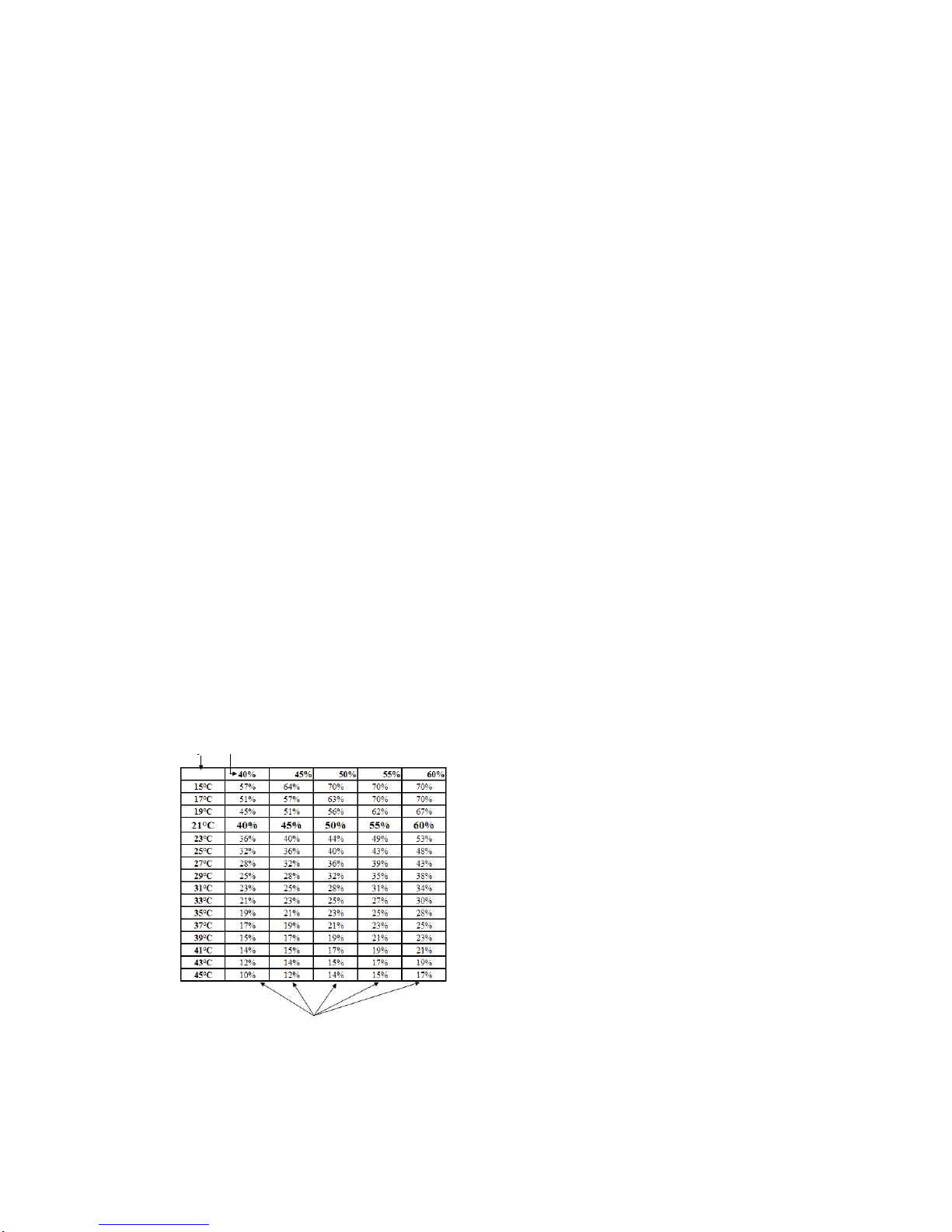
humidity in living areas. The surface temperature of the components must lie above the dew point
temperature of the indoor air (at least about +15°C).
In normal operation, germs or mould cannot form inside the device unit since the humidification water is
continuously treated and disinfected during operation.
Mounting
The device is intended for horizontal mounting. It may deviate a maximum of +/-1° from the horizontal
position and must be mounted to a massive wall that can bear the load. The intrinsic operating weight of
the air humidification unit must be taken into consideration for the suspension. No shocks or jolts may
affect the device. For mounting and setup, the national and local regulations must be observed. The
device may be installed only in compliance with the national installation regulations.
Electrical connection
The electrical connection of the supply and sensor line should be performed by an electrician
according to the local regulations. Before the device is opened, the voltage supply must be shut
off at all poles and secured against reactivation. If the mains connecting line of the device is damaged or
defective, it must be repaired or replaced immediately to prevent risks. This work may be performed only
by authorised expert personnel.
Water connections
The water, heating, and waste water connections must be established by an expert. For the connection to
the water supply, only the original connecting hoses provided in delivery may be used. Pay attention to the
seal tightness of the lines. The maximum water pressure of the mains water supply of 0.7 MPa and of the
water heater battery of 1 MPa may not be exceeded.
Water quality
Only mains water that corresponds with the local mains water ordinance may be used for the water supply.
The water inlet pipe to the air humidification unit should be established using optionally available
connection sets.
In case of a chlorine content over 0.1 mg/l, the standard water filter (5 μm) must be replaced by a dual
filter (5 μm/carbon). If the iron content of the mains water exceeds a value of 0.1 mg/l, an iron filter should
also be built into the water inlet pipe.
The device can be used for a maximum hardness of water of 26°dH. When this value is exceeded, the
service life of the reverse osmosis membrane is considerably reduced.
Operation of the device
Every working method that impairs the safety of the device is prohibited. All warning and safety devices
should be regularly checked for proper function. Safety devices may not be disassembled or
decommissioned.
Mounting, disassembly, maintenance, and servicing of the device
If maintenance work or repairs are performed, the device should be de-energised. The attachment or
installation of additional equipment is not permitted. In this case, please consult with the manufacturer.
Electrical system/electronics Work on the electrical plant parts may be performed only by
electricians. If maintenance work or repairs are performed, the device should be de-energised.
In case of faults in the electrical voltage supply, shut down the device immediately. Use only
original fuses with the required current strength. Check the electrical equipment of the device regularly.
Discovered defects like loose connections or scorched cables must be eliminated immediately. After the
electrical work or servicing has been performed, the safety measures should be tested (e.g. earthing
resistance).
Requirement on the installation site
The installation of the air humidification unit may take place only in rooms that have an existing water
outlet. In addition, safety measures that automatically close the water supply to the air humidification unit
in case of leakage (e.g. safety valve/water connection set) must be taken within the room. The air
humidification unit is designed in IP20 type of protection.

6.Transport and storage and disposal
To prevent damage during transport due to force, the air humidification unit must be handled carefully.
During transport by hand, reasonable human lifting and carrying forces must be observed.
Age Reasonable load in kg
Women Men
15 – 18 years 15 35
19 – 45 years 15 55
Over 45 years 15 45
The unit may not be transported by the connecting cable. Impacts and shocks should be avoided.
6.1 Dimensions and weight
Dimensions of the packing unit
LBE 250: Width: 800 mm, height: 460 mm, depth: 420 mm
LBE 500: Width: 870 mm, height: 600 mm, depth: 600 mm
Weight of the packing unit:
LBE 250 28 kg without optional accessories
LBE 500 62 kg without optional accessories
6.2 Packaging
The safety labels attached to the box absolutely must be observed. During delivery, look out for and check
any damage to the packaging or device. Problems or damage must be reported immediately.
6.3 Storage
The device must be stored in the packaging in a dry, dust-free, and frost-protected manner. Avoid storage
periods that are too long (recommendation: one year maximum).
6.4 Check for completeness
When the device is delivered, make sure:
The type and serial numbers on the type plate correspond with the information in the order and
delivery documents.
The equipment (optional accessories) is complete.
All parts are present in a perfect state.
Note: In case of any transport damage and/or missing parts, you must inform the transport company or
suppler immediately in writing.
6.5 Scope of supply
The delivery comprisesthe following:
• the air humidification unit
• the operating and mounting instructions
• accessories like: the water connection set (see Section 16.3)
• optional accessories like: the pumps/mixer connection set (see Section 16.4)
6.6Waste Disposal
Care has to be taken that the packing material and the protective packing are disposed of in an
environmentally friendly way. The packing materials have to be disposed of in accordance with the local
stipulations, for example, wooden pallets and cardboard packing have to be recycled.
Units that are no longer in working order have to be dismantled and properly disposed of by a
specialized company via suitable collection centres and in compliance with the waste electrical
and electronic equipment ordinance (WEEE), which provides for ratification of community law,
directive 202/95/EC (RoHS) and the directive 2002/96/EC (the WEEE directive).

7.Structure
1. Water tank
2. Motor
3. UVC pipe for disinfection
4. Sensor plate with a temperature and humidity sensor
5. Inlet valve
6. UVC pipe series connection unit
(LBE 250, 1 pc / LBE 500, 2 pcs)
7. Reverse osmosis membrane
8. Outlet pump
9. Electronic operation system
10. Main board
11. Bladed rotary evaporator
12. Warm water heater battery (air side)

8. Description of functions
8.1 Working principle
The air humidification unit works according to the principle of natural evaporation and guarantees a
constant relative air humidity that can be adjusted between 40% and 60% in the supply air. The unit works
automatically, and the air humidity is electronically monitored in the device. The indoor air can thus not be
overhumidified.
The air humidification unit is dimensioned for a maximum operating air volume flow of 250 m³/h (LBE 250)
/ 500 m³/h (LBE 500). The water tank is supplied with mains water from the mains water supply. According
to the evaporative power, a maximum of 2.5 litres of water, which is continuously placed, is located in the
tank.
The maximum filling level is limited using a floating switch and mechanical overflow. The water in the tank
is continuously disinfected using UVC light, whereby the UVC pipe illuminates the complete water tank and
evaporation surface. The UVC pipe has a radiant power of 4.3 watt at a wavelength of 253.7 nm. For
safety reasons, the UVC pipe is monitored by UV diode. This monitoring process can detect a failure,
soiling, or line breakage of the disinfection unit. If the radiant power is too low, the water is drained and a
error message is output. The unit is automatically shut down in case the UVC pipe malfunctions.
To prevent deposits during operation, especially scale deposits on the bladed rotary evaporator and the
water tank, the standard version of the air humidification unit is equipped with a reverse osmosis unit. In
the standard design, the reverse osmosis unit is integrated into the water inlet pipe between the solenoid
valve and the water tank.
A prefiltering unit for the water supply, which should be installed during the course of mounting, is included
in the scope of supply. As an additional safety measure, the water is drained and an error message output
in case of the air humidity is exceeded by more than 30% of the reference value of the water for longer tan
25 hours.
8.2 Humidity control
The air humidity is controlled using the water moistened surface of the bladed rotor and the water level in
the tank. As the water level rises, the rotor blades are submerged more deeply into the water, increasing
the surface area of the blades that becomes wet. The passing air flow absorbs moisture from the wet
blades, in accordance with a specific reference value that is set as a constant. However, as a rule the set
relative humidity is converted to the relevant absolute humidity at 21 °C (factory setting) and then
controlled.
Measured
temperature
Set
humidity
Controlled humidity

8.3 Temperature control
The air outlet temperature of the humidification unit is controlled either by the sensor built into the device
or by an external sensor, where one has been attached. In case of a connected external sensor, the
control system automatically switches to external temperature control. In the display, the letter "E"
appears after the temperature. TemperatureE 21°C<
Function view:
9. Control system
The device is provided in a preprogrammed manner and can be commissioned immediately after all
connections (air, water, and electrical) have been established.
9.1 Operation/keypad/display
The first two lines on the display show the operational menu, the third line shows the operational status.
The display illumination is switched off 10 minutes after the entry of the last command and can be
reactivated by turning the scroll wheel (energy-saving mode).
<Scroll Wheel>: Select or set the position by turning, confirm or save by pressing. The less-than
character on the right edge of the display labels the respectively selected value.
<On/Off>: Activation and deactivation of the device
<Back>: Go back a step in the selection

9.2 Customer menu
(The frame text represents the display view)
9.3 Settings
Temperature 21°C<
With the Temperature parameter, the air temperature at the outlet of the air humidification unit is
set between 15°C and 25°C in one degree intervals. A value of 21°C is preset at the factory.
With the TemperatureE parameter (E = external temperature sensor), the desired air
temperature at the external sensor is set between 15°C and 25°C in one degree intervals.
Humidity 50%<
•With the Humidity parameter, the desired outlet humidity is set between 40% and 60 %
relative humidity at five percent intervals. A value of 50 % relative humidity is preset at the
factory.
Service <
• In the Service menu item, information regarding the operational status is displayed.
Internal Sensor < Temperature 21 °C
Humidity 50 %
Internal Sensor shows the currently measured air temperature and the relative humidity at the
air outlet of the air humidification unit.
External Sensor < Ext. Sensor 21°C
External Sensor indicates the currently measured air temperature at the external temperature
sensor. If a sensor is not connected, the Ext. Sensor display is not connected!
Info < Software version
V 1.0 01.09.08
The installed software version is shown under Info.

Delete
Fault
<
Delete Yes<
Fault? No
Error messages, which appear in the Info line of the display, are deleted using the Delete Fault
Yes< function.
Expert < Code?
--------------
•With Expert, you can access the next lower menu level by entering a code. This parameter can
be opened only by the respective expert.
10. Operational statuses
10.1 Automatic activation/
deactivation Autumn/Spring (Auto STANDBY)
The air humidification unit switches on when the air humidity is too low (Autumn) and off when
the air humidity is too high (Spring). The following appears on the display: Auto STANDBY
If the evaporative power within 24 hours is less than one litre, the device switches off (Auto
STANDBY).
If the humidity undershoots the set humidity by 7% for a period of 24 hours, the air humidification
unit switches on again.
10.2 Automatic activation/deactivation (Auto STANDBY)
If the On/Off button is pressed, the following appears on the display: Auto STANDBY
The air humidification unit is switched off and set to the Auto STANDBY mode.
If the air humidity falls by 7% under the set value for a period of 24 hours, the air humidification
unit switches on again.
10.3 Manual activation/deactivation (Manu STANDBY)
If the On/Off button on the key pad is pressed for longer than 3 seconds, the following appears
on the display: Manu STANDBY
In this operational status, the air humidification unit remains switched off. The water is drained
and the UVC pipe and the rotor are switched off with a delay of 20 minutes. The air humidification
unit must be switched on again by hand. To do so, press the On/Off button for 3 seconds.
10.4 Automatic activation/deactivation depending on air current ("Control Off")
The humidification is controlled automatically by the operation of the ventilation device. In the
process, an acoustic signal indicates whether the ventilation and air conditioning system is
running.
Depending on this signal, the air humidification unit switches on and off automatically.
CONTROL ON / CONTROL OFF
If the ventilation and air conditioning system is shut down for longer than 18 hours, the air
humidification unit switches off automatically. Auto STANDBY.
During the operation of the ventilation and air conditioning system, it switches on automatically
again.

10.5 Rinsing
The water inlet pipe and the reverse osmosis membrane are protected against germs by the
rinsing program.
The rinsing program is performed automatically once a day while the air humidification unit is
shut down.
"RINSING" is shown in the display.
The rinsing period amounts to 10 minutes and can be cancelled by pressing the "Back" button
10.6 Control on
This parameter indicates that the humidity and air temperature control are active.
10.7 Fill
This parameter indicates that the tank is being filled with water. Manu STANDBY
10.8 Water replacement
The water in the tank is replaced one to four times a day (LBE 250) or twice a day (LBE 500)
depending on the evaporative power and the degree of hardness of the supply water
(corresponds to 1 to 10 litres of water a day / LBE 250 or 2 to 30 litres a day / LBE 500). The
following appears in the display: WAT.REP.
11.Error messages
In the case of error messages, an alarm sounds which can be deactivated by pressing or turning
the <scroll wheel>. The error messages are shown in the display.
After each error message (with the exception of Service and Filter Change), the water is
drained and the air humidification unit is switched off. The error messages can be deleted by
pressing the "Back" button and keeping it pressed for 3 seconds or in the Service menu under
the Delete Fault Yes< item.
After that, the air humidification unit re-enters the operating mode. The expert/Service
department should be informed in case of error messages, with the exception of the Filter
Change message.
11.1 Filter change! (customer)
• The water filter in the water inlet pipe should be changed (see Section 10).
11.2 UVC pip defective! (expert)
The UVC pipe is monitored continuously. A failure is detected automatically. The UVC pipe
should be changed by the expert/Service department every two years. Only original UVC pipes
should be used. In case replica components are used, the warranty extinguishes and a guarantee
of function cannot be provided.
Remedy of the fault only by the expert: Change the UVC pipe under observance of the safety
measures.
11.3 Descaling! (expert)
During operation the UV radiation decreases continuously. As soon as the radiant power drops
below 20% of the calibrated value, this fault message is output.

• Remedy of the fault only by the expert: Open the device under observance of the safety
measures and remove deposits in the tank, on the rotor, on the UVC pipe etc. using descaling
agent and then rinse them with water.
11.4 Pump, outlet defective! (expert)
If the floating switch actuates during the water replacement, the existing water cannot be drained.
Remedy of the fault only by the expert: Check the pump, outlet, and floating switch.
11.5 Humidity too high! (expert)
If the relative humidity exceeds the reference value by 25% for a period of 25 hours, the water is
drained and the unit switches off.
Remedy of the fault only by the expert: Check the inlet value and integrated humidity sensor.
11.6 Humidity too low! (expert)
• If the relative humidity undershoots the reference value by 20% for a period of 25 hours, the
water is drained and the unit switches off.
• Remedy of the fault only by the expert: Check the inlet valve, motor, integrated humidity sensor,
and reverse osmosis membrane for proper function. (Reverse osmosis membrane blocked.
11.7 Service (expert)
• The service message is set to an interval of 8600 operating hours by default.
• Remedy of the fault only by the expert: The device should be serviced according to Section 18.
12. Maintenance (customer): "Filter Change"
The water filter in the water inlet pipe must be exchanged every six months. The filter change is
displayed automatically by the air humidification unit by the output of the "Filter Change!" error
message.
a) Switch off the air humidification unit.
b) Shut off the water supply upstream of the filter unit.
c) Hold the container under the filter housing. (Water may emerge.)
d) Open the filter housing.
e) Remove the filter and replace it with a new one.
f) Close the housing and turn on the water supply again - do not forget to pay attention to seal
tightness.
g) Keep the "Back" button pressed for three seconds. The error message on the display is deleted.
Figure 1 – Filter housing and filter
Where do I order the filters?
Use only original replacement filters.
J. Pichler Gesellschaft m.b.H.
9021 KLAGENFURT
Karlweg 5, Postfach 32
T
+43 (0)463 32769
Designation Item number
Water filter 40E0003A

13.Commissioning
After all complete connections have been established (ventilation, water, and electrical), the air
humidification unit can be commissioned.
Caution!
The device may be commissioned only by qualified experts. The commissioning program
must be completely completed to start the device.
After the mains plug is plugged in, the following appears on the display:
The supply water should be tested using the test strip included in the delivery (immerse the test
strip in water, shake the strip, and check the colour after one minute). The hardness of water
(°dH) determined in this manner should be entered according to the table.
1 = up to 5°dH
1.5 = 6 – 8°dH
2 = 9 – 11°dH
2.5 = 12 – 14°dH
3 = 15 – 17°dH
3.5 = 18 – 20°dH
4 = 21 – 23°dH
4.5 = 24 – 26°dH
After the hardness of water is set, the following appears: UV calibration
>On Off
"On" starts the UV calibration (the program runs for about three minutes).
Display:
In the case of the UVC calibration, the light output of the UVC pipe is determined and saved as a
calibrated value (= reference value of the new pipe).
When the program is needed, the following appears in the display for 8 seconds:
Calibration successful!
After that, the air humidification unit automatically switches to operating mode.
If no UVC radiation is determined, the following appears on the display:
UVC pipe or sensor defective!
Trans.lock rem?
Yes < No
Calib. Started
Duration: 3 min
Water RUNNING
Circ. Pump On<
Open Mixer On<
Off
Close Mixer On<
Off
Hardness of water
3.0
Only in case of a device water heater battery
Test strip for determining the hardness of water

Remedy of the fault only by the expert:
Check the UVC pipe, series connection unit (green function LED), and sensor board for function.
After the commissioning of the device, the function and operation should be observed for about 15
minutes.
If leaks are found on the water or air side or if disturbing noises are noticed, shut down the device
immediately.
In this case, have the determined faults remedied immediately under observance of the safety
regulations.
If something is not clear or if you have questions, contact the expert/Service department or
manufacturer immediately.
Caution!
After commissioning, the current supply may not be interrupted for longer than one day so that the
hygienic requirements can be observed.
In case of an interruption in the electrical voltage supply of more than 24 hours, the air humidification unit may
become contaminated with germs. In this case, a general cleaning of all components should be performed before
the unit is commissioned. If necessary, components must be replaced.

14.Expert menu
14.1 Expert menu overview
TempControl
Int.Sensor <
Ext.Sensor

14.2 Settings
This shows whether the air temperature is controlled via the internal or external sensor.
In the case of the Int. Sensor display, the outlet air temperature of the air humidification unit is
constantly regulated to the reference value set in the customer menu.
In the case of the Ext. Sensor display, the outlet air temperature is regulated depending on the
external temperature sensor.
According to the mounting site of the temperature sensor (in the extract air line in case of air
heating or after the second air heater battery in case of low-temperature heating), the device
regulates the temperature to the temperature reference value. The air outlet temperature of the
air humidification unit is limited to a minimum of +16°C and a maximum of +35°C by the software.
Hardness of water < Hardness of water
0,3<
Set the existing hardness of water. (See Section 11 "Installation.")
UV calibration < UV calibration
<On Off
The UV Calibration must always be performed when the UVC pipe is exchanged. (See Section
11 "Installation.")
Control by < Air Curr. Meas
Switch Input.
Using Control by <, the parallel control between the ventilation device and the air humidification
unit can be selected.
In the case of the Switch Input presetting, a control cable must be connected from the
ventilation device to the input of the air humidification unit. This cable makes contact whilst the
ventilation device is running and breaks contact when it is shut down.
In the case of the Air Current Measurement selection, the operational status of the ventilation
device is automatically determined using the installed microphone and the air humidification unit
is actuated synchronously (factory setting).
Elect. Heating < Elect. Heating Act<
Deact.
The Elect. Heating parameter shows the operational status for the activated heater battery.
When Elect. Heating Act. < is set, the control system is programmed for the actuation of an
electric heater battery.
When Elect. Heating Deact. < is set, the control system is programmed for the actuation of a
water heater battery.

In the following items, the relay outputs can be activated and deactivated manually.
When Elect.Heating Act. is set, the Open Mixer and Close Mixer items are replaced by
and
With the UVC Check parameter is set, the current light output of the UVC pipe is determined.
At the right bottom, the current value and the value calibrated underneath that (light output of the
new pipe) is displayed. In comparison with the calibrated value, the light output is shown as a
percentage.
This parameter is used to check the function of the floating switch. When the float is raised, the
">" character changes from Off to On.
The opening time for the water valve is set when the water tank is filled (water level after water
replacement).
Setting range: 20 – 600 seconds / Factory setting: 260 seconds
This parameter is used to set the refill time of the water during humidity control. The air humidity
is determined every minute. When the reference value is undershot, the valve is opened
according to a set value.
Setting range: 1 – 70 seconds / Factory setting: 30 seconds
With this parameter, the runtime of the mixer can be set.
Setting range: 2 – 30 seconds / Factory setting: 6 seconds
With the Time Interval Mixer parameter, the interval time according to which the control system
readjusts the mixer can be set.
Setting range: 1 – 120 minutes / Factory setting: 5 minutes
Motor
Motor On<
Off
Valve
Valve On<
Off
Circulation pump <
Cir. Pump On<
Off
Wat.Soft.Pump <
Wat.Soft.Pump On<
Off
Discharge pump <
Disch.Pump On <
Off
Elect.Heating1 <
Elect.Heating1 On<
Off
Open Mixer <
Open Mixer On<
Off
UVC Lamp
UVC Lamp On<
Off
Close Mixer <
Close Mixer On<
Off
Fan <
Fan On<
Off
Horn <
Horn On<
Off
Elect.Heating 2 <
Elect.Heating 3
UVC Check <
UVC check 3.65
80 % Cal. 4.56
Floating switch
Floating switch
<On Off
Time Valve
Wat. Repl <
Time Valve
Wat. Repl <
Time Valve Ctrl.
Time Valve Ctrl.
030s
Runtime Mixer
Runtime Mixer
006s
Time Int. Mixer
Time Int. Mixer
005min
Other manuals for LBE 250
1
This manual suits for next models
1
Table of contents
Other Pichler Humidifier manuals
Popular Humidifier manuals by other brands

DèLonghi
DèLonghi Tasciugo DDS 20 instruction manual

Hunter
Hunter 33520 owner's manual

DriSteem
DriSteem VT Series Installation, operation and maintanance manual

Germguardian
Germguardian H4600 Use and care instructions

nor-tec
nor-tec RH2 Installation and operation manual

AIRINNOVATIONS
AIRINNOVATIONS PERSONAL HUMIDIFIER user guide

Easy@Home
Easy@Home 1094S2022 user manual

Duracraft
Duracraft DCM-200 Series owner's manual

Air King
Air King AK4500 Installation, operation, & maintenance instruction

Perfect Aire
Perfect Aire 2PFD22 Faq

Aircare
Aircare 4DTS 900 Setup guide and owners manual

Germguardian
Germguardian H1500 Use & care instructions