Pichler LBE 250 Service manual

Systematic ventilation.
COMFORT
VENTILATION
OPERATING AND
MOUNTING INSTRUCTIONS
LBE 250 / LBE 500

OPERATING AND INSTALLATION INSTRUCTIONS LBE 250 / LBE 500 PAGE 2
GENERAL
USER
SPECIALIST PERSONNEL
Contents
General
1. Introduction Page 4
2. Intended use Page 4
2.1 LIABILITY PAGE 5
2.2 WARRANTY 5
3. Safety Instructions Page 6
4. Transport and storage Page 8
4.1 DIMENSIONS AND WEIGHT 8
4.2 PACKAGING 8
4.3 STORAGE 8
4.4 CHECK FOR COMPLETENESS 8
4.5 SCOPE OF SUPPLY 8
4.6 WASTE DISPOSAL 9
5. Structure Page 9
6. Versions Page 10
7. Description of functions Page 10
7.1 WORKING PRINCIPLE 10
7.2 HUMIDITY CONTROL 11
7.3 TEMPERATURE CONTROL 12
User
8. Control system Page 13
8.1 OPERATION/KEYPAD/DISPLAY 13
8.2 CUSTOMER MENU 13
8.3 SETTINGS 14
9. Operational statuses Page 14
9.1 AUTOMATIC ACTIVATION/DEACTIVATION AUTUMN/SPRING (AUTO STANDBY) 14
9.2 AUTOMATIC ACTIVATION/DEACTIVATION (AUTO STANDBY) 15
9.3 MANUAL ACTIVATION/DEACTIVATION (MANU STANDBY) 15
9.4 AUTOMATIC ACTIVATION/DEACTIVATION DEPENDING ON AIR CURRENT („CONTROL OFF“) 15
9.5 RINSING 15
9.6 CONTROL ON 15
9.7 FILL 15
9.8 WATER REPLACEMENT 16
10. Error messages Page 16
10.1 FILTER CHANGE! (CUSTOMER) 16
11. Maintenance (customer) „Filter change“ Page 16

OPERATING AND INSTALLATION INSTRUCTIONS LBE 250 / LBE 500 PAGE 3
GENERAL
USER
SPECIALIST PERSONNEL
specialist personnel
12. Commissioning Page 17
12.1 POSSIBLE FAULT MESSAGE 18
13. Expert menu Page 19
13.1 EXPERT MENU OVERVIEW 19
13.2 SETTINGS 20
14. Technical data Page 25
15. Layout sketch Page 26
15.1 LAYOUT SKETCH LBE 250 (WALL-MOUNTED) 26
15.2 LAYOUT SKETCH LBE 500 (WALL-MOUNTED) 27
16. Mounting Page 28
17. Connections/installation Page 29
17.1 ROUTING OF AIR LINES 29
17.2 WASTE WATER CONNECTION 29
17.3 MAINS WATER CONNECTION 30
17.4 WATER HEATER BATTERY CONNECTION 30
17.5 HYDRAULIC CONNECTION DIAGRAM 31
17.6 LOW TEMPERATURE HEATING 31
18. Wiring diagram Page 34
19. Error messages (expert) Page 35
19.1 UVC PIPE DEFECTIVE! (EXPERT) 35
19.2 DESCALING! (EXPERT) 35
19.3 PUMP, OUTLET DEFECTIVE! (EXPERT) 35
19.4 HUMIDITY TOO HIGH! (EXPERT) 35
19.5 HUMIDITY TOO LOW! (EXPERT) 36
19.6 SERVICE (EXPERT) 36
20. Maintenance (expert) Page 37
20.1 UVC TUBE REPLACEMENT 37
20.2 OSMOSIS MEMBRANE REPLACEMENT 39
20.3 CLEANING 41
20.4 DECALCIFICATION 42
21. Spare parts and accessories Page 45
22. EC Declaration of Conformity Page 46
23. Subject to change without notice Page 47

OPERATING AND INSTALLATION INSTRUCTIONS LBE 250 / LBE 500 PAGE 4
2. Intended use
1. Introduction
Dear Customer,
Thank you for purchasing the LBE 250/
LBE 500 air humidification unit.
The LBE 250/LBE 500 air humidification
unit is available in two versions and
corresponds to state-of-the-art tech-
nology. It convinces through operating
safety, operating comfort, and economic
eciency.
To operate your air humidification unit
safely, properly, and economically, care-
fully read and observe these operating
instructions.
Use the air humidification unit only
when it is in a perfect state in a proper,
safety and risk conscious manner under
consideration of all information in these
instructions.
If you have further questions, please
contact us.
In case of inquiries and spare parts
orders, please have the device type and
serial number (see the type plate on the
device) on hand!
Please keep these operating instructions
in a safe place that is always accessible.
Please contact us in case of a loss of the
documentation.
The LBE 250/LBE 500 air humidifica-
tion unit is intended for immediate or
later installation into ventilation and air
conditioning systems with a maximum
air volume flow of 250 m³/h (LBE 250) or
500 m³/h (LBE 500).
This device, which is accessible to the
general public, is intended for installati-
on in residential or commercial buil-
dings.
It is used for active indoor air humidifi-
cation and can also be used for auxiliary
heating.
The compact air humidification unit
works according to the principle of
natural evaporation and guarantees
constant, optimum indoor air humidity in
living areas, adjustable in a range from
40 % to 60 % relative humidity.
In addition, a constant supply air tem-
perature that can be adjusted within a
range from 15 °C to 25 °C is generated
by an integrated air heater battery.
As a part of intended use, our required
operating and mounting instructions
must also be observed.
Only qualified, assigned personnel may
work on and with the device. People
who transport or work on the device
must have read and understood the
corresponding parts of the operating
instructions, especially Chapter 3 „Safety
Instructions.“, page 6.
In addition, the plant installer must in-
form the end user of any possible risks.
The LBE 250/LBE 500 air humidification
unit is not a product that is ready for
use. It may not be commissioned until
it has been properly installed into the
ventilation and air conditioning system
and connected.
The air humidification unit is not suited
for outdoor setup. It may only be used in
suitable, temperature-controlled indoor
rooms.
Subject to technical changes.
We are constantly performing technical
improvements and optimisations on your
products and reserves the right to mo-
dify the devices or technical data without
prior notice.
SPECIALIST PERSONNEL GENERAL
USER
J. Pichler Gesellschaft m.b.H.
9021 KLAGENFURT
Karlweg 5
T +43 (0)463 32769

OPERATING AND INSTALLATION INSTRUCTIONS LBE 250 / LBE 500 PAGE 5
2.1 LIABILITY
The warranty begins with initial startup,
at the latest, however, one month after
delivery has taken place. The warranty
covers the pure replacement of materials
only and does not include any claims for
the compensation of services. It applies
only if there is proof of appropriately per-
formed maintenance in accordance with
our regulations and by a licensed compa-
ny that specializes in installation work.
The warranty right extends to a maximum
term of 24 months after installation of
the air humidification unit LBE 250/500,
however, up to a maximum of 30 months
after the manufacturing date.
Warranty claims can be asserted only for
material and/or design defects that have
occurred during the warranty term. In the
event of a warranty claim the air humi-
dification unit LBE 250/500 must not be
dismantled without the previous written
authorization of the manufacturer. The
manufactureraccords a warranty on spa-
re parts only if they have been installed
by an installer who is recognized by the
manufacturer.
The warranty shall lapse automatically
upon expiry of the warranty period, in
the event of improper operation, e.g.
operation without a filter, if genuine parts
supplied by the manufacturer are not
installed, in the event of non-authorized-
changes or modifications that have been
performed on the air humidification unit.
Failure to comply with these Operating
and Installation Instructions will automati-
cally void all warranties.
2.2 WARRANTY
Air treatment unit for the active humi-
dification of indoor air and for auxiliary
heating of air in living spaces, patented
and tested system, suitable for install-
tion or retrofitting in ventilation and air
conditioning systems.
Any other use shall be deemed improper
and may cause personal injury or da-
mage to the air humidification unit LBE
250/500, for which the manufacturer
shall accept no liability.
The manufacturer shall accept no liabi-
lity for any damages due to:
• Non-observance of the Safety, Opera-
ting and Servicing instructions in these
Operating and Installation Instructions.
• Installation of spare parts not supplied
by the manufacturer, whereby the
responsibility for the use of such
spare parts shall rest with the
installer of the equipment.
• Normal wear and tear.
SPECIALIST PERSONNEL GENERAL
USER

OPERATING AND INSTALLATION INSTRUCTIONS LBE 250 / LBE 500 PAGE 6
3. Safety Instructions
General information
The following safety symbols indicate
text passages that warn against risks
and sources of danger. Please familiari-
se yourself with these symbols.
The non-observance of this
warning can lead to injury or
danger to life and limb and/or
damage of the device.
Dangerous electrical voltage!
The non-observance of this
warning can lead to injury or
danger to life and limb.
General safety notices
All safety and danger notices located
on the device must be observed. In case
of malfunctions, shut down the device
immediately and secure it against acti-
vation. Malfunctions must be eliminated
immediately.
After servicing work, have expert per-
sonnel re- establish the operating safety
of the device. Use only original spare
parts. For the operation of the device,
the national regulations also apply wit-
hout limitation.
READ THESE OPERATING
INSTRUCTIONS CAREFULLY
AND FOLLOW THE SAFETY
NOTICES.
Damage arising from a non-observance
of the operating and maintenance inst-
ructions is not covered by the guarantee.
This device is not intended to be used by
people (including children) with limited
physical, sensory, or mental capabili-
ties or with a lack of experience and/
or knowledge, unless supervised by
a person who is responsible for their
safety or who instructs them in the use
of the device. Make sure that children do
not play with the device.
After commissioning, the
current supply may not be
interrupted for longer than one
day so that the hygienic requirements
can be observed.
In case of an interruption in the elec-
trical voltage supply of more than 24
hours, the air humidification unit may
become contaminated with germs. In
this case, a general cleaning (a cleaning
agent on an organic basis) of all com-
ponents should be performed before
the unit is commissioned. If necessary,
components must be replaced.
Deactivation of the ventilation and air
conditioning system
If the ventilation and air conditioning
system is decommissioned for more
than one day, the air humidification
unit must be shut down beforehand for
at least two hours. In this way, the air
humidification unit can thus dry out and
hygienically perfect function is guaran-
teed.
Working on the device
Mounting, commissioning,
maintenance, and repairs must
be performed by an authorized expert
(heating specialist firm/installation
specialist firm).
When working on the device,
de- energise it and secure it
against reactivation. The water
supply must be shut o.
UVC disinfection pipes
A UVC pipe ( Art.No. 40I0023A)
is installed into the standard
version of the device! It may only be
replaced by a type listed on the label of
the device. UVC pipes may be changed
only by authorised expert personnel! Be-
fore the unit is opened or a UVC pipe is
changed, the device absolutely must be
de-energised and the mains plug must
be pulled. Never look directly into the lit
UVC light source without eye protection.
SPECIALIST PERSONNEL GENERAL
USER

OPERATING AND INSTALLATION INSTRUCTIONS LBE 250 / LBE 500 PAGE 7
Device setup/installation
The device may be installed only in
frost-free, dry rooms. The room tem-
perature must lie between +5 °C and a
maximum of +40 °C.
Ventilation and air conditioning system
air lines that are not installed in heated
areas must be designed with suitable
heat insulation (danger when the dew
point temperature is undershot) to pre-
vent the formation of condensation.
For components or windows with bad
heat insulation properties, in case
of missing construction, and in old
buildings, condensation may form on
window glass at cold temperatures and
in case of increased air humidity in living
areas. The surface temperature of the
components must lie above the dew
point temperature of the indoor air (at
least about +15 °C).
In normal operation, germs or mould
cannot form inside the device unit since
the humidification water is continuously
treated and disinfected during operation.
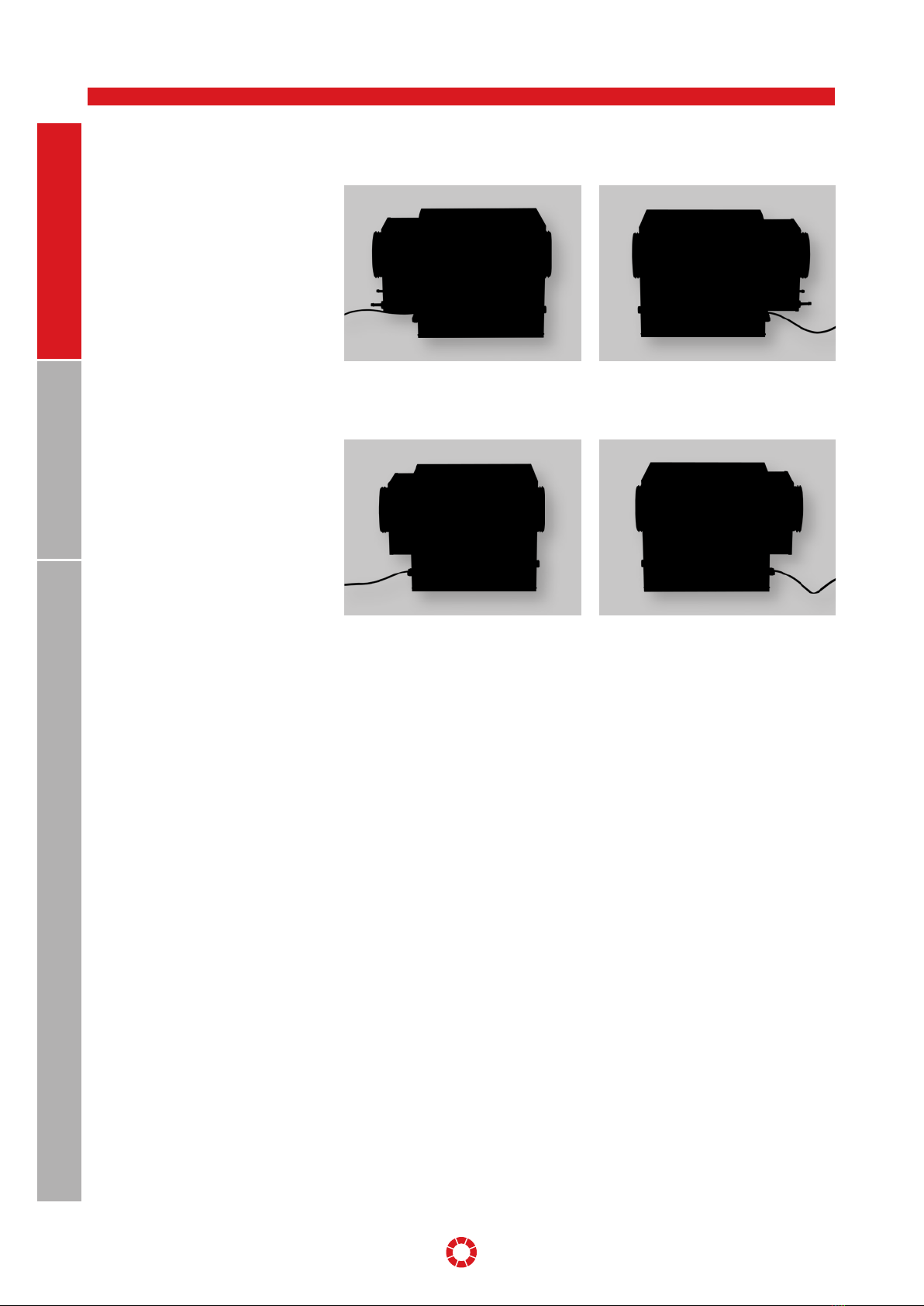
Mounting
The device is intended for horizontal
mounting. It may deviate a maximum of
+/-1° from the horizontal position and
must be mounted to a massive wall that
can bear the load. The intrinsic opera-
ting weight of the air humidification unit
must be taken into consideration for the
suspension. No shocks or jolts may af-
fect the device. For mounting and setup,
the national and local regulations must
be observed. The device may be installed
only in compliance with the national
installation regulations.
Electrical connection
The electrical connection of the
supply and sensor line should
be performed by an electrician accor-
ding to the local regulations. Before the
device is opened, the voltage supply
must be shut o at all poles and secu-
red against reactivation. If the mains
connecting line of the device is dama-
ged or defective, it must be repaired or
replaced immediately to prevent risks.
This work may be performed only by
authorised expert personnel.
Water connections
The water, heating, and waste water
connections must be established by an
expert. For the connection to the water
supply, only the original connecting
hoses provided in delivery may be used.
Pay attention to the seal tightness of the
lines. The maximum water pressure of
the mains water supply of 0.7 MPa and
of the water heater battery of 1 MPa may
not be exceeded.
Water quality
Only mains water that corresponds with
the local mains water ordinance may
be used for the water supply. The water
inlet pipe to the air humidification unit
should be established using optionally
available connection sets.
In case of a chlorine content over 0.1
mg/l, the standard water filter (5 μm)
must be replaced by a dual filter (5 μm/
carbon). If the iron content of the mains
water exceeds a value of 0.1 mg/l, an
iron filter should also be built into the
water inlet pipe.
The device can be used for a maximum
hardness of water of 26° dH. When this
value is exceeded, the service life of the
reverse osmosis membrane is conside-
rably reduced.
Operation of the device
Every working method that impairs the
safety of the device is prohibited. All
warning and safety devices should be
regularly checked for proper function.
Safety devices may not be disassembled
or decommissioned.
Mounting, disassembly, maintenance,
and servicing of the device
If maintenance work or repairs are per-
formed, the device should be de-ener-
gised. The attachment or installation of
additional equipment is not permitted.
In this case, please consult with the
manufacturer.
SPECIALIST PERSONNEL GENERAL
USER

OPERATING AND INSTALLATION INSTRUCTIONS LBE 250 / LBE 500 PAGE 8
Electrical system/electronics
Work on the electrical plant
parts may be performed only
by electricians. If maintenance work or
repairs are performed, the device should
be de-energised. In case of faults in the
electrical voltage supply, shut down the
device immediately. Use only original
fuses with the required current strength.
Check the electrical equipment of the
device regularly. Discovered defects like
loose connections or scorched cables
must be eliminated immediately. After
the electrical work or servicing has been
performed, the safety measures should
be tested (e.g. earthing resistance).
Requirement on the installation site
The installation of the air humidifica-
tion unit may take place only in rooms
that have an existing water outlet. In
addition, safety measures that automa-
tically close the water supply to the air
humidification unit in case of leakage
(e.g. safety valve/water stop) must be
taken within the room. The air humidi-
fication unit is designed in IP20 type of
protection.
4. Transport and storage
To prevent damage during transport due
to force, the air humidification unit must
be handled carefully. During transport
by hand, reasonable human lifting and
carrying forces must be observed.
The unit may not be transported by the
connecting cable. Impacts and shocks
should be avoided.
Age Reasonable load in kg
Women Men
15 – 18 years 15 35
19 – 45 years 15 55
Over 45 years 15 45
4.1 DIMENSIONS AND WEIGHT LBE 250 LBE 500
Dimensions of the packing unit (B x H x T) 800 x 460 x 420
mm
870 x 600 x 600
mm
Weight of the packing unit without optional accessories 28 kg 62 kg
4.2 PACKAGING The safety labels attached to the box ab-
solutely must be observed. During deli-
very, look out for and check any damage
to the packaging or device. Problems or
damage must be reported immediately.
4.3 STORAGE The device must be stored in the pa-
ckaging in a dry, dust-free, and frost-
protected manner. Avoid storage periods
that are too long (recommendation: one
year maximum).
4.4 CHECK FOR COMPLETENESS When the device is delivered, make
sure:
• The type and serial numbers on the
type plate correspond with the infor-
mation in the order and delivery docu-
ments.
• The equipment (optional accessories)
is complete.
• All parts are present in a perfect state.
Note: In case of any transport damage
and/or missing parts, you must inform
the transport company or suppler imme-
diately in writing.
4.5 SCOPE OF SUPPLY The delivery comprises the followin:
• the air humidification unit
• the operating and mounting instruc-
tions
• accessories like: the water connection
set (see Chapter 17.3)
• optional accessories like: the pumps/
mixer connection set (see Chapter 17.4)
SPECIALIST PERSONNEL GENERAL
USER

OPERATING AND INSTALLATION INSTRUCTIONS LBE 250 / LBE 500 PAGE 9
5. Structure
1
2
3
4
5678
9
10
11
12
SPECIALIST PERSONNEL GENERAL
USER
1 Water tank
2 Motor
3 UVC pipe for disinfection
4 Sensor plate with a temperature and
humidity sensor
5 Inlet valve
6 UVC pipe series connection unit
7 Reverse osmosis membrane
(LBE 250, 1 pc / LBE 500, 2 pcs)
8 Outlet pump
9 Electronic operation system
10 Main board
11 Bladed rotary evaporator
12 Warm water heater battery (air side)
Care has to be taken that the packing
material and the protective packing
are disposed of in an environmentally
friendly way. The packing materials have
to be disposed of in accordance with the
local stipulations, for example, wooden
pallets and cardboard packing have to
be recycled.
Care has to be taken that the
packing material and the pro-
tective packing are disposed of
in an environmentally friendly
way. The packing materials have to
be disposed of in accordance with the
local stipulations, for example, wooden
pallets and cardboard packing have to
be recycled.
4.6 WASTE DISPOSAL

OPERATING AND INSTALLATION INSTRUCTIONS LBE 250 / LBE 500 PAGE 10
6. Versions
LBE with warm water heater battery
(for connection on the left)
Item number: 08LBE250LW, 08LBE500LW
LBE with warm water heater battery
(for connection on the right)
Item number: 08LBE250RW, 08LBE500RW
LBE with PTC electric heater battery
(for connection on the left)
Item number: 08LBE250LE
LBE with PTC electric heater battery
(for connection on the right)
Item number: 08LBE250RE
SPECIALIST PERSONNEL GENERAL
USER
7. Description of functions
7.1 WORKING PRINCIPLE The air humidification unit works
according to the principle of natural
evaporation and guarantees a constant
relative air humidity that can be adjusted
between 40 % and 60 % in the supply air.
The unit works automatically, and the air
humidity is electronically monitored in
the device. The indoor air can thus not
be overhumidified.
The air humidification unit is dimensi-
oned for a maximum operating air
volume flow of 250 m³/h (LBE 250) /
500 m³/h (LBE 500). The water tank is
supplied with mains water from the
mains water supply. According to the
evaporative power, a maximum of 2.5
litres of water, which is continuously
placed, is located in the tank. The
maximum filling level is limited using a
floating switch and mechanical overflow.
The water in the tank is continuously
disinfected using UVC light, whereby the
UVC pipe illuminates the complete water
tank and evaporation surface. The UVC
pipe has a radiant power of 4.3 watt at a
wavelength of 253.7 nm.
For safety reasons, the UVC pipe is
monitored by UV diode. This monitoring
process can detect a failure, soiling, or
line breakage of the disinfection unit. If
the radiant power is too low, the water is
drained and a error message is output.
The unit is automatically shut down in
case the UVC pipe malfunctions. To
prevent deposits during operation,
especially scale deposits on the bladed
rotary evaporator and the water tank,
the standard version of the air humidifi-
cation unit is equipped with a reverse
osmosis unit. In the standard design, the
reverse osmosis unit is integrated into
the water inlet pipe between the
solenoid valve and the water tank.
A prefiltering unit for the water supply,
which should be installed during the
course of mounting, is included in the
scope of supply. As an additional safety
measure, the water is drained and an
error message output in case of the air
humidity is exceeded by more than 25 %
of the reference value of the water for
longer tan 25 hours.

OPERATING AND INSTALLATION INSTRUCTIONS LBE 250 / LBE 500 PAGE 11
The air humidity is controlled using the
water moistened surface of the bladed
rotor and the water level in the tank. As
the water level rises, the rotor blades
are submerged more deeply into the
water, increasing the surface area of the
blades that becomes wet.
The passing air flow absorbs moisture
from the wet blades, in accordance with
a specific reference value that is set as a
constant. However, as a rule the set rela-
tive humidity is converted to the relevant
absolute humidity at 21 °C (factory
setting) and then controlled.
7.2 HUMIDITY CONTROL
Measured
temperature Set humidity
15 °C 57 % 64 % 70 % 70 % 70 %
17 °C 51 % 57 % 63 % 70 % 70 %
19 °C 45 % 51 % 56 % 62 % 67 %
21 °C* 40 %* 45 %* 50 %* 55 %* 60 %*
23 °C 36 % 40 % 44 % 49 % 53 %
25 °C 32 % 36 % 40 % 43 % 48 %
27 °C 28 % 32 % 36 % 39 % 43 %
29 °C 25 % 28 % 32 % 35 % 38 %
31 °C 23 % 25 % 28 % 31 % 34 %
33 °C 21 % 23 % 25 % 27 % 30 %
35 °C 19 % 21 % 23 % 25 % 28 %
37 °C 17 % 19 % 21 % 23 % 25 %
39 °C 15 % 17 % 19 % 21 % 23 %
41 °C 14 % 15 % 17 % 19 % 21 %
43 °C 12 % 14 % 15 % 17 % 19 %
45 °C 10 % 12 % 14 % 15 % 17 %
*) Controlled humidity (factory setting)
SPECIALIST PERSONNEL GENERAL
USER

OPERATING AND INSTALLATION INSTRUCTIONS LBE 250 / LBE 500 PAGE 12
SPECIALIST PERSONNEL GENERAL
USER
The air outlet temperature of the hu-
midification unit is controlled either by
the sensor built into the device or by an
external sensor, where one has been
attached. In case of a connected external
sensor, the control system automatically
switches to external temperature con-
trol. In the display, the letter „E“ appears
after the temperature.
7.3 TEMPERATURE CONTROL
2
3
4
8
7
6
5
13
12
11
10
9
1
1 Outlet
2 Osmotic outlet
3 Bladed rotary evaporator
4 Water
5 Outlet pump
6 Water tank
7 Reverse osmosis membrane
8 UVC pipe for disinfection
9 Inlet valve
10 Floating switch
11 UVC pipe series connection unit
12 Free outlet (water inlet)
13 Motor
Illustration: Function view
TemperatureE21°C <

OPERATING AND INSTALLATION INSTRUCTIONS LBE 250 / LBE 500 PAGE 13
8. Control system
The device is provided in a preprogram-
med manner and can be commissioned
immediately after all connections (air,
water, and electrical) have been estab-
lished.
The first two lines on the display show
the operational menu, the third line
shows the operational status.
The display illumination is switched o
10 minutes after the entry of the last
command and can be reactivated by
turning the scroll wheel (energy-saving
mode).
<Scroll Wheel>: Select or set the
position by turning, confirm or save by
pressing. The less-than character on
the right edge of the display labels the
respectively selected value.
<On/O>: Activation and deactivation of
the device.
<Back>: Go back a step in the selection.
8.1 OPERATION/KEYPAD/DISPLAY
8.2 CUSTOMER MENU
Temperature 21 °C
Humidity 50%
Service Internal Sensor Temperature 21 °C
Humidit
y
50 %
Ex
te
rn
a
l
Se
n
so
r Ext. Sensor 21 °C
D
e
l
ete
F
au
l
t
Info
Fault Yes
delete? No
Software version
V 1.0 23.07.08
Expert Code?
------
USER GENERALSPECIALIST PERSONNEL

OPERATING AND INSTALLATION INSTRUCTIONS LBE 250 / LBE 500 PAGE 14
8.3 SETTINGS
• With the Temperature parameter, the air temperature at
the outlet of the air humidification unit is set between 15
°C and 25 °C in one degree intervals. A value of 21 °C is
preset at the factory.
• With the TemperatureE parameter (E = external tempe-
rature sensor), the desired air temperature at the exter-
nal sensor is set between 15 °C and 25 °C in one degree
intervals.
• With the Humidity parameter, the desired outlet humi-
dity is set between 40 % and 60 % relative humidity at
five percent intervals. A value of 50 % relative humidity is
preset at the factory.
• In the Service menu item, information regarding the ope-
rational status is displayed.
• Internal Sensor shows the currently measured air tem-
perature and the relative humidity at the air outlet of the
air humidification unit.
• External Sensor indicates the currently measured air
temperature at the external temperature sensor.
• If a sensor is not connected, the Ext. Sensor display is not
connected!
• The installed software version is shown under Info.
• Error messages, which appear in the Info line of the dis-
play, are deleted using the Delete Fault Yes< function.
• With Expert, you can access the next lower menu level by
entering a code. This parameter can be opened only by
the respective expert.
9. Operational statuses
9.1 AUTOMATIC ACTIVATION/DEACTIVATION AUTUMN/SPRING (AUTO STANDBY)
• The air humidification unit switches on when the air hu-
midity is too low (Autumn) and o when the air humidity
is too high (Spring). The following appears on the dis-
play: auto STANDBY.
• If the evaporative power within 24 hours is less than one
litre, the device switches o (auto STANDBY).
• If the humidity undershoots the set humidity by 7 % for
a period of 24 hours, the air humidification unit switches
on again.
a
uto S
TANDBY
CONTROL ON
USER GENERALSPECIALIST PERSONNEL
Temperature 21°C <
Humidity 50 %<
Service <
Internal Sensor < Temperature 21 °C
Humidity 50 %
External Sensor < Ext. Sensor 21 °C
gExt. Sensor display is not connected!
Info < V 1.0
Software Version
01.09.08
Delete Fault < Delete Yes<
Fault? No
Expert < Code?
------

OPERATING AND INSTALLATION INSTRUCTIONS LBE 250 / LBE 500 PAGE 15
9.2 AUTOMATIC ACTIVATION/DEACTIVATION (AUTO STANDBY)
• If the On/O button is pressed, the following appears on
the display: auto STANDBY.
• The air humidification unit is switched o and set to the
auto STANDBY mode.
• If the air humidity falls by 7 % under the set value for a
period of 24 hours, the air humidification unit switches
on again.
a
uto S
TANDBY
9.3 MANUAL ACTIVATION/DEACTIVATION (MANU STANDBY)
• If the On/O button on the key pad is pressed for longer
than 3 seconds, the following appears on the display:
manu STANDBY.
• In this operational status, the air humidification unit re-
mains switched o. The water is drained and the UVC
pipe and the rotor are switched o with a delay of 20 mi-
nutes.
• The air humidification unit must be switched on again by
hand. To do so, press the On/O button for 3 seconds.
manu STANDBY
9.4 AUTOMATIC ACTIVATION/DEACTIVATION DEPENDING ON AIR CURRENT („CONTROL OFF“)
• The humidification is controlled automatically by the
operation of the ventilation device. In the process, an
acoustic signal indicates whether the ventilation and air
conditioning system is running.
• Depending on this signal, the air humidification unit
switches on and o automatically.
• If the ventilation and air conditioning system is shut
down for longer than 18 hours, the air humidification
unit switches o automatically. Auto STANDBY.
• During the operation of the ventilation and air conditio-
ning system, it switches on automatically again.
/
CONTROLL ON CONTROLL OFF
a
uto S
TANDBY
9.5 RINSING
• The water inlet pipe and the reverse osmosis membrane
are protected against germs by the rinsing program.
• The rinsing program is performed automatically once a
day while the air humidification unit is shut down. „RIN-
SING“ is shown in the display.
• The rinsing period amounts to 10 minutes and can be
cancelled by pressing the „Back“ button.
RINSING
• This parameter indicates that the humidity and air tem-
perature control are active.
9.6 CONTROL ON
CONTROL ON
• This parameter indicates that the tank is being filled
with water.
FILL
9.7 FILL
USER GENERALSPECIALIST PERSONNEL

OPERATING AND INSTALLATION INSTRUCTIONS LBE 250 / LBE 500 PAGE 16
• The water in the tank is replaced one to four times a
day (LBE 250) or twice a day (LBE 500) depending on the
evaporative power and the degree of hardness of the
supply water (corresponds to 1 to 10 litres of water a
day / LBE 250 or 2 to 30 litres a day / LBE 500). The fol-
lowing appears in the display: WAT.REP.
9.8 WATER REPLACEMENT
WAT. REP.
10. Error messages
In the case of error messages, an alarm
sounds which can be deactivated by
pressing or turning the <scroll wheel>.
The error messages are shown in the
display. After each error message (with
the exception of Service and Filter
Change), the water is drained and the air
humidification unit is switched o. The
error messages can be deleted by pres-
sing the „Back“ button and keeping it
pressed for 3 seconds or in the Service
menu under the Delete Fault Yes< item.
After that, the air humidification unit re-
enters the operating mode.
The expert/Service depart-
ment should be informed in
case of error messages, with
the exception of the Filter Change
message.
• The water filter in the water inlet pipe should be chan-
ged (see Chapter 11).
10.1 FILTER CHANGE! (CUSTOMER)
Filter change!
USER GENERALSPECIALIST PERSONNEL
11. Maintenance (customer) „Filter change“
• The water filter in the water inlet pipe must be ex-
changed every six months. The filter change i s dis-
played automatically by the air humidification unit by the
output of the „Filter Change!“ err or message.
Filter change
1) Switch o the air humidification unit.
2) Shut o the water supply upstream of the filter unit.
3) Hold the container under the filter housing. (Water
may emerge)
4) Open the filter housing.
5) Remove the filter and replace it with a new one.
6) Close the housing and turn on the water supply again
- do not forget to pay attention to se al tightness.
7) Keep the „Back“ button pressed for three seconds.
The error message on the display is deleted.
J. Pichler Gesellschaft m.b.H.
9021 KLAGENFURT
Karlweg 5
T +43 (0)463 32769
Where do I order the filters?
Use only original replacement filters.
Designation Item number
Water filter 40E0003A
Illustration: Filter housing and filter

OPERATING AND INSTALLATION INSTRUCTIONS LBE 250 / LBE 500 PAGE 17
• After all complete connections have been established
(ventilation, water, and electrical), the air humidification unit
can be commissioned.
The device may be commissioned only by qualified
experts. The commissioning program must be
completely completed to start the device.
After the mains plug is plugged in, the following appears on
the display:
• The supply water should be tested using the test strip
included in the delivery (immerse the test strip in water,
shake the strip, and check the colour after one minute). The
hardness of water (°dH) determined in this manner should
be entered according to the table.
• After the hardness of water is set, the following appears:
„UV Calibration <On/O“.
• „On“ starts the UV calibration (the program runs for about
three minutes).
• In the case of the UVC calibration, the light output of the UVC
pipe is determined and saved as a calibrated value
(= reference value of the new pipe).
• When the program is needed, the following appears in the
display for 8 seconds. Display: (see the picture opposite).
• After that, the air humidification unit automatically switches
to operating mode.
12. Commissioning
Hardness of water
3.0?
Circ. Pump On<
Off
Close Mixer On<
Off
Open Mixer On<
Off
Trans.lock rem?
Yes <
No
Only in case of a
device water
heater battery
1=bis 5 ° dH
1,5 = 6 – 8 ° dH
2= 9 – 11 ° dH
2,5 = 12 – 14 ° dH
3= 15 – 17 ° dH
3,5 = 18 – 20 ° dH
4= 21 – 23 ° dH
4,5 = 24 – 26 ° dH
Illustration: Test strip for determining the hardness of water
UV calibration
> On Off
Calib. Started
Duration: 3 min
Water RUNNING
Calibration successful!
USER GENERALSPECIALIST PERSONNEL
Illustration: Removing the transport locking device
Hardness of water
3.0?
Circ. Pump On<
Off
Close Mixer On<
Off
Open Mixer On<
Off
Trans.lock rem?
Yes <
No
Hardness of water
3.0?
Circ. Pump On<
Off
Close Mixer On<
Off
Open Mixer On<
Off
Trans.lock rem?
Yes <
No
Hardness of water
3.0?
Circ. Pump On<
Off
Close Mixer On<
Off
Open Mixer On<
Off
Trans.lock rem?
Yes <
No
Hardness of water
3.0?
Circ. Pump On<
Off
Close Mixer On<
Off
Open Mixer On<
Off
Trans.lock rem?
Yes <
No

OPERATING AND INSTALLATION INSTRUCTIONS LBE 250 / LBE 500 PAGE 18
UVC pipe or
sensor defective!
After the commissioning of the device,
the function and operation should be
observed for about 15 minutes. If leaks
are found on the water or air side or if
disturbing noises are noticed, shut down
the device immediately. In this case,
have the determined faults remedied
immediately under observance of the sa-
fety regulations. If something is not clear
or if you have questions, contact the
expert/Service department or manufac-
turer immediately.
After commissioning, the
current supply may not be
interrupted for longer than one
day so that the hygienic requirements
can be observed.
In case of an interruption in the elec-
trical voltage supply of more than 24
hours, the air humidification unit may
become contaminated with germs. In
this case, a general cleaning (a cleaning
agent on an organic basis) of all com-
ponents should be performed before
the unit is commissioned. If necessary,
components must be replaced.
USER GENERALSPECIALIST PERSONNEL
Hardness of water
3.0?
Circ. Pump On<
Off
Close Mixer On<
Off
Open Mixer On<
Off
Trans.lock rem?
Yes <
No
12.1 POSSIBLE FAULT MESSAGE
• If no UVC radiation is determined, the following appears on
the display (see the picture opposite).
• Remedy of the fault only by the expert:
Check the UVC pipe, series connection unit (green function
LED), and sensor board for function.

OPERATING AND INSTALLATION INSTRUCTIONS LBE 250 / LBE 500 PAGE 19
13. Expert menu
13.1 EXPERT MENU OVERVIEW
Expert TempControl Int. Sensor
Ext. Sensor
Hardness of water
UV calibration
Control by
Elect. Heating
Circ.Pump
Wat.Soft.Pump
Hardness of water
3.0
UV calibration
On Off
Switch input
Air Curr. Meas..
Elect. Heating Act.
Deact.
Circ.Pump On
Off
Wat.Soft.Pump On
Off
Motor
Valve
Open Mixer
Discharge Pump
Close Mixer
Motor On
Off
Valve On
Off
Open Mixer On
Off
DischargePump On
Off
Close Mixer On
Off
Elect.Heating 1
Fan
UVC Check
Horn
UVC Lamp
Elect.Heating 1 On
Off
Fan On
Off
UVC Lamp On
Off
Horn On
Off
UVC Check 4,52
80% Cal:5,65
USER GENERALSPECIALIST PERSONNEL
Time Valve
Wat.Rep.
Floating switch
Time Valve
Wat.Re
p
. 260s
Floating switch
On Of
f
Time Valve Ctrl. -
030s
Time Valve Ctrl.
R
u
n
t
im
e
Mix
e
r
Tim
e
In
t
. Mix
e
r
Time Rinsing
R
eset
U
V
C
UVC Operation
Error Messages
Time Int. Mixer
005min
Time Rinsing
010min
Runtime Mixer
006s
01: No Fault
Rec.
UVC Operation
00001 h
Reset UVC
Y
es No
F
act
.
Sett
in
g
Air Curr.Setup
Descaling
Fact.Setting Yes
load? No
Hi:680 Lo:260
Dta:080 F1 +-1
Descaling On
Of
f
Air Heating Air Heating On
Of
f
Status storage
AutoStby activ
Ext.Temp.Offset
Status storage 1
S: 15m 10h 003d
AutoStby activ On
4 Of
f
Ext.Temp.Offset
+0.0
Language English
German Of
f
Humidity max. 80 %
Humidity rel.
Humidity max. On
Of
f
Humidity rel. On
Of
f
4
Temp.abs.humid. Temp.abs.humid.
21°C<
Ext. Off On
Of
f
<
250 <
500
Ext. Off
Softwaretyp

OPERATING AND INSTALLATION INSTRUCTIONS LBE 250 / LBE 500 PAGE 20
13.2 SETTINGS
• This shows whether the air temperature is controlled via
the internal or external sensor.
• In the case of the Int. Sensor display, the outlet air tem-
perature of the air humidification unit is constantly regu-
lated to the reference value set in the customer menu.
• In the case of the Ext. Sensor display, the outlet air tem-
perature is regulated depending on the external tempe-
rature sensor.
• According to the mounting site of the temperature sen-
sor (in the extract air line in case of air heating or after
the second air heater battery in case of low-temperature
heating), the device regulates the temperature to the
temperature reference value. The air outlet temperature
of the air humidification unit is limited to a minimum of
+16°C and a maximum of +35°C by the software.
• Set the existing hardness of water.
(See Chapter 12 Commissioning.)
• The UV Calibration must always be performed when the
UVC pipe is exchanged.
(See Chapter 12 Commissioning.)
• Using Control by <, the parallel control between the ven-
tilation device and the air humidification unit can be se-
lected.
• In the case of the Switch Input presetting, a control
cable must be connected from the ventilation device to
the input of the air humidification unit. This cable ma-
kes contact whilst the ventilation device is running and
breaks contact when it is shut down.
• In the case of the Air Current Measurement selection,
the operational status of the ventilation device is auto-
matically determined using the installed microphone
and the air humidification unit is actuated synchronously
(factory setting).
• The Elect. Heating parameter shows the operational sta-
tus for the activated heater battery.
• When Elect. Heating Act. < is set, the control system is
programmed for the actuation of an electric heater bat-
tery.
• When Elect. Heating Deact. < is set, the control system
is programmed for the actuation of a water heater bat-
tery.
<Int. Sensor
Ext. Sensor
Temp. Controll <
<Hardness of water Hardness of water
3.0<
UV calibration < UV calibration
>On Off
Elect. Heating < Elect. Heating Act.
Deact.<
Control by Switch input <Air Curr. Meas.
USER GENERALSPECIALIST PERSONNEL
Other manuals for LBE 250
1
This manual suits for next models
1
Table of contents
Other Pichler Humidifier manuals