Pichler Sania 1550 User manual

Directions for use of PICHLER Whirlpool
S
Sa
an
ni
ia
a
1
15
55
50
0
i
in
nc
cl
lu
ud
di
in
ng
g
A
Au
ut
to
om
ma
at
ti
ic
c
S
Sp
pa
a
W
Wa
at
te
er
r
T
Tr
re
ea
at
tm
me
en
nt
t
S
Sy
ys
st
te
em
m
PICHLER Kunststofftechnik GmbH
Lauterbachstrasse 19
D-84307 Eggenfelden
Phone:
0 87 21-96 90 10
Fax:
0 87 21-96 90 20
E-Mail:
mail@pichler.de
Web:
www.pichler-whirlpool.de
State:
2013-03-25

PICHLER Kunststofftechnik GmbH
Page 2 of 26
C
Co
on
nt
te
en
nt
ts
s
Placement..................................................................................................... 3
Electricity Supply......................................................................................... 3
Safety and Health......................................................................................... 3
Initial Operation ........................................................................................... 4
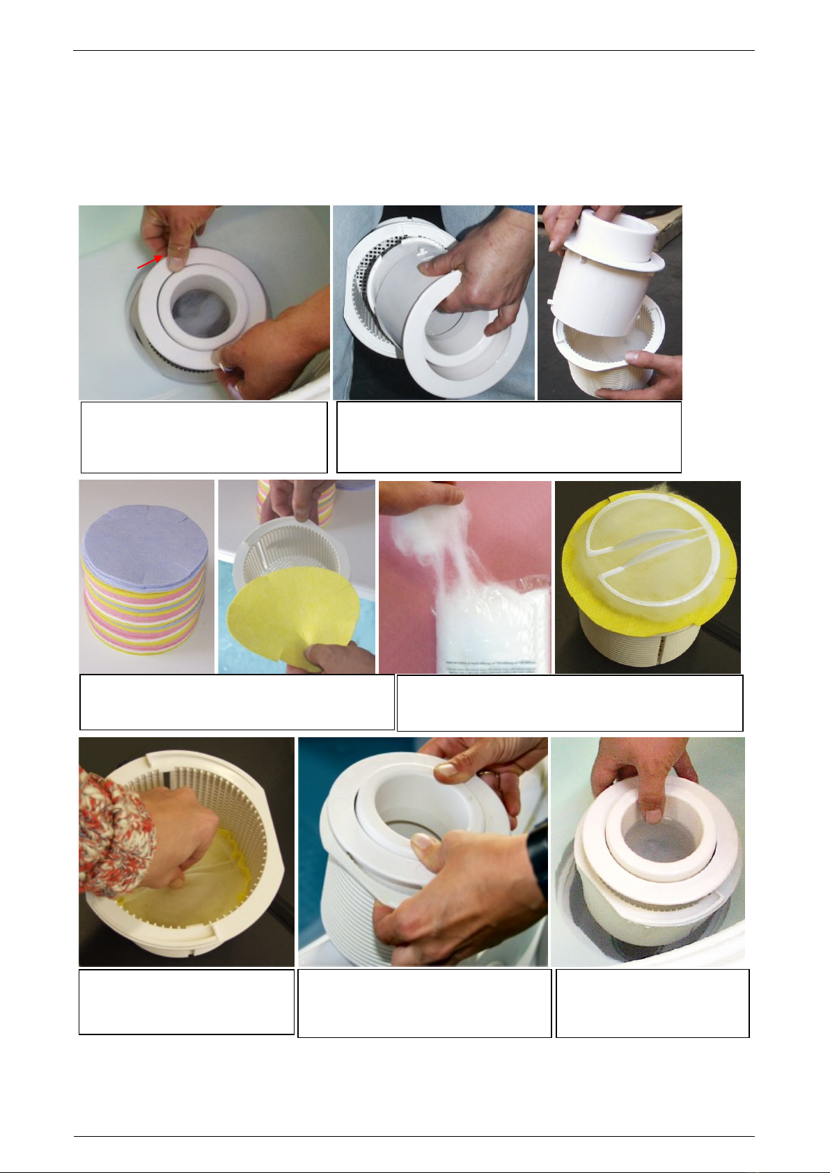
Preparing the Filter Unit .......................................................................................................4
Filter rmaterial of Pichler-QC-Filtersystem....................................................................................... 4
Water Treatment..................................................................................................................5
Pool Care...................................................................................................... 5
Placing out of Operation ............................................................................. 7
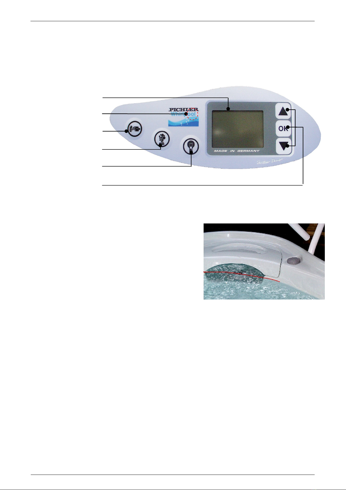
Whirlpool Controller .................................................................................... 8
Automatically functions ...................................................................................8
Trouble Shooting ...................................................................................11,13
Equipment Sania 1550............................................................................... 19
Controlling jet output with electrical valve control ..............................................................20
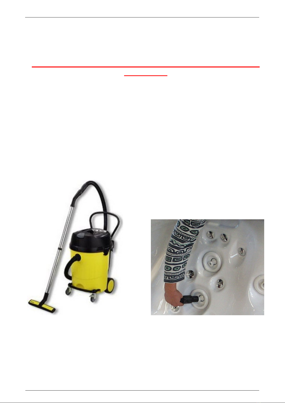
Massage jets......................................................................................................................21
Coloured Light Therapy Module (optionally) ......................................................................23
Service-Illumination (optionally) .........................................................................................23
Technical Specifications ........................................................................... 24
Plug on the whirlpool on electric power supply ..................................................................24
Wiring diagram of strip terminal Sania 1550 (three-phase current 400V) ............................ 25
Wiring diagram of strip terminal Sania 1550 (AC current 230V)............................................ 25
Layout Power Board................................................................................................................... 26
Manual of Automatic Spa Water Treatment System.................................27

PICHLER Kunststofftechnik GmbH
Page 3 of 26
Congratulations for purchasing a PICHLER-Whirlpool. You made a decision for a high quality product
that will enjoying and relaxing you for many times.
If you have questions which could not be clarified by these instructions, so please direct your enquiry to your
special dealer or to us.
Placement
Your new PICHLER whirlpool needs for placement a planar horizontally ground which have to guarantee a
static load of about 450 kg/m² (static load value of full filled Pool, including bathers!). The basement of the whirl-
pool have to lie completely flush with the surface!
All flooring, wall and ceiling coating have to be resistant for bathrooms. Steam and splash water might cause
damaging your building.
In the worst case all water of the pool can leak by a technical defect or pipe burst or something like that. There-
fore it would be necessary to have a sufficient water outlet at the placement.
We point out that you are responsible for having direct access to the whirlpool and his components by repair or
maintenance.
Maintenance work could only be done if the access is available to concerning places at the pool.
For this work also keep the stairs free for getting access. At Sania 1550 it concerns also all rear area of external
skirt.
Electricity Supply
To connect the electricity supply of the PICHLER Whirlpool is only to be allowed by a qualified electrician. You
will find the exactly dates at “Electricity Supply” by this instructions.
Safety and Health
Enter whirlpool cautious (slip hazard) and not alone.
Do not use the whirlpool under influence of alcohol, drugs or medicine.
Do not set the bath temperature more than 38°C (danger of body overheating).
Do not stay too long at the pool. This can endanger your health. (If you are not sure because of your
physical constitution you should consulting your doctor!)
We would recommend that you are showering before going into the pool. So the pollution of the pool
water is reduced.
Never let children alone nearby the whirlpool! The insulation cover is no protection!
Do not place electrical equipment nearby the pool (radio, hairdryer, a.s.o.)
Keep away from children the chemicals for water care.

PICHLER Kunststofftechnik GmbH
Page 4 of 26
Initial Operation
Before initial operation the whirlpool should be spring-cleaned. There should be no foreign particles in the whirl-
pool. Especially look at the area around the filter unit.
Preparing the Filter Unit
Filter rmaterial of Pichler-QC-Filtersystem
The filter material should be exchanged regularly. As a basic principle: After bathing in the pool change the
filter leaf and filter cotton!
Unlock the dowel bolt of skimmer tubes by pushing
together the outer skimmer basket and take the skim-
mer cartridge.
Take a filter leaf and put it on the empty skimmer
basket.
Lock the dowel bolt by plugging the
skimmer tubes into the skimmer basket
tightly.
Plug the skimmer basket into
the filter cage and fix it by
turning right.
Push it down with the clip to the
bottom of the skimmer basket.
The clip remains there!
Turn the skimmer basket left until the
flattened surfaces are on top of each
other. Than remove from filter cage.
Then arrange about ½0from a full package of filter
cotton on the filter leaf. Put the clip on it.

PICHLER Kunststofftechnik GmbH
Page 5 of 26
Initial Operation
Filling the Whirlpool
Control Element
The following map shows the control element of the whirlpool and gives you an overview about the buttons you
partly need for initial operation. Circumstantial explanations for operating and programming the control are fol-
lowing later in accordant parts of these instructions.
The whirlpool starts running by switching-on the fuses.
Caution: Never fill the pool with hot water! Risk of damage!!
Fill the whirlpool with cold water until target
value of water level (see on picture). If the
minimum water level is attained the filter circu-
lation, ozone generator and heating automati-
cally would be activated. The pool will be heat-
ing up until the adjusted target value of tem-
perature.
Water Treatment
Now starts water treatment, i.e. from this time on you have to do something for the water quality of your whirl-
pool.
Pool Care
Changing of Filter materials
The filter material should be exchanged regularly. As a basic principle: about 24 hours after bathing in the pool
change the filter leaf and filter cotton! Approach: (see page 3, chapter „Initial Operation“)
Cleaning of Plastic surfaces
The acrylic tub of your whirlpools has an approved surface. For routine cleaning it is sufficient to fill the tub with
warm clear water and clean with some filter cotton (it has got characteristics like micro fibre cloth). Then dry the
surface with tissue.
LCD - Display
Reset - Button (invisible)
Jet - Pumps
Air - Blower
Pool Illumination
Programming - Keys
Target value of
water level at the
filter unit

PICHLER Kunststofftechnik GmbH
Page 6 of 26
Pool Care
Fragrances
We strongly advise against using of water additives which are oil-based like
fragrances o.s.. This affects adversely the water quality and contained fat sedi-
ments at water tubes which could cause malfunction. For whirlpools with scent
dispenser are suitable fragrance bags available. The air is pressed through the
scent dispenser into jets. The bags with scent pearls should be exchanged all 1
to 2 month.
CAUTION:
Please do not use other additives in the scent dispenser. They could contain
solvents which are damaging the plastic of scent dispenser.
Indoor Insulation Cover
If you want to clean the cover use some filter cotton. It has got characteristics like micro fibre cloth. For cleaning
up older and tenacious stains we advise using a chlorine solution all 3 month. You need 10 ml chlorine granu-
lates into 2 litres of water. After cleaning the insulation cover rinse with clear water.
Please always wear rubber gloves by making and using a chlorine solution!
Never fill leavings in bottles or containers which children could suspect drinkable content!
To let of Water
To let of water you have to plug a tube at the drain (attachment ¾ inch).
You find the drain at the black base tub underneath the steps. Open the
outlet valve.
By let of water equipment will be automatically switched of. At the dis-
play appears „Wasserstand korrigieren“ (correct water level). Then
remove filter cotton and filter leaf.
If the pool is empty switch on the air blower for about 1 minute to blow
out water in the air lines.
Now you can switch off the whirlpool. Turn off the fuse of
the whirlpool.
Then you could clean your whirlpool in-depth.
Refill the Pool
You have to close the outlet valve and turn on the fuse. Then follow the
instructions on page 5 for filling the pool.
Pay attention during the refill that no splash water get on the area which is
signed with red line. (On the backside are water level sensors which send
a signal to the digital controller. The Pool will be switched on and water in
the lines would be spout.)
drain

PICHLER Kunststofftechnik GmbH
Page 7 of 26
Placing out of Operation
Sometimes the pool will be getting out of operation over a longer period, f.e. over the winter. For a closedown
follow the instructions on page 6 „To let of water“.
Remaining water in the whirlpool could cause severe damages
on freezing!
There is no guarantee from the producer on frost damages.
Repairing a frozen whirlpool needs an extensive work which could avoid on following instructions.
Let the outlet valve open after letting out
You should all jets, the filter unit and the drain sucking empty with an water exhauster.
Sucking the Whirlpool empty
The water will be suck with a commercial wet and dry exhauster from the pool, all jets and the filter unit. Press
the suction hose directly on the respective jet. Then you have to suck remaining water from the ground of the
pool.
Wet and Dry Exhauster Rotary jets

PICHLER Kunststofftechnik GmbH
Page 8 of 26
Placing out of Operation
Acupressure jets Turbo jets
Ozone jet Ground of the pool

PICHLER Kunststofftechnik GmbH
Page 9 of 26
Placing out of Operation
Sparkling air jets
If you don´t have the possibility to switch on the air blower again to blow out remaining water in the air lines, you
must additionally sucking the sparkling air jets. There for you have to unscrew the cover of these jets.
To unscrew cover Sucking the jet
Outlet valve
At last you have the suck the outlet valve.
Let the outlet valve necessarily open!

PICHLER Kunststofftechnik GmbH
Page 10 of 26
Placing out of Operation
Now you can clean your whirlpool in-depth.
Follow the instructions on page 5, cleaning of plastic surfaces.
Protection on outskirt area
During the standing idle of the whirlpool which is not filled you have to assure with an adequate cover that no
water, dirt or objects could get in the pool. Dirt can infiltrate the pipes. If there are lay down any objects in or on
the pool they could damage the surface of the pool. Later infiltration of water can cause damage of freezing in
the line system! You could order these outskirt cover. Always you should cover your pool with it.

PICHLER Kunststofftechnik GmbH
Page 11 of 26
Whirlpool Controller
Automatically Functions
Trouble detection
Whirlpool controller detects errors and advises on display. A message is indicated until she will be entered with
„OK“. Not until then the next message will be shown. The active message will be advised at least.
In the following chart all kinds of errors and their cause are listed.
Advice on display
Cause
Phase 2 absent
Phase 3 absent
Detect phase: L2 and/or L3 on power supply fails
Jumper on power board is not plugged
Defective rotatin field
Detect rotating field: Rotating field is interchanged (Clockwise rotation field
is needed)
Water temperature over the
maximum value
Measured water temperature has increased over the maximum value of
42°C.
Ozon generator error
Ozone lamp or restrictor are defective. Check the fuse on board when
changing ozone generator (see on page 26).
Air blower error
Air blower motor is defective. Check the fuse on board by changing air
blower (see on page 26).
Water - or Temperatur error
Heating control is activated and has detected an error.
No water flow at heating
Cause: Foreign particles are in the pump or before it.
Air in filter cycle
Motor 2 overheats
Motor 3 overheats
Motor overheat control is activated and has detected an error.
Low stage of water
Water level lies under the upper sensor.
Ozon generator error
Air blower error
If their are detected error of ozone generator and error of air blower simul-
taneous, it is to assume that a fuse on board is defective (see on page 26).
Cause: Ozone generator is defective, air blower is defective or short circuit
in device, however it could be lightning or overvoltage.
If you even could not switch on the whirlpool you should be checking the transformer fuse on
board (see on page 26).
Trouble Shooting
In the following the most questions and problems are answered. Also you come to know how to resolve that.
Sparkling air jets does not work
Try out different positions on servo valves and air control.
Water temperature constantly increase
If the water temperature constantly is increasing by switched of heating (that means „HEIZUNG“ is not dis-
played) you have to discover the insulation cover from time to time. Cause: Filter pump and ozone generator get
very warm by being in use. This causes a constantly increasing temperature of the water. The problem espe-
cially appears in warm month or in well tempered rooms (f.e. bath rooms, winter garden, a.s.o.).

PICHLER Kunststofftechnik GmbH
Page 12 of 26
To Remove Outside skirt
For maintenance and repair work you could remove the outside skirt as per description on
following pages:
Needed tool:
Allen key Size: 4
Step skirt
1Remove star grip screws under step
skirt on the left and right side.
2Unscrew Allen keys size 4 in front of
step skirt.
Remove stair skirt careful.
Put it down on the right side Pay
attention to wiring for step light!
LED lighting at hand rail –pull off the
cap, than LED could be pull off.
LED can not slip and disappear in the
hand rail.
1
2
2
1

PICHLER Kunststofftechnik GmbH
Page 13 of 26
Trouble Shooting
To Remove Outside skirt
Corner part (on the back side left and right) and back side skirt
Remove star grip screws
under corner skirt.
Careful push down the
corner skirt and lift it from
adjustment. Then put it
down.
Remove star grip screws
under back side skirt on.
Remove star grip screws
on back side skirt on the
left and right side.
Then put it down.

PICHLER Kunststofftechnik GmbH
Page 14 of 26
Trouble Shooting
Water leakage
If your whirlpool looses water you first should check all compression couplings of heating and pumps. Maybe a
gasket has yielded.
To check this components step skirt must have been removed (see on page 18).
1. Tighten the compression couplings of heating and pumps with both hands as strong as possible.
compression couplings of pump 3
compression couplings of heating
compression couplings
of pump 1

PICHLER Kunststofftechnik GmbH
Page 15 of 26
Trouble Shooting
Water leakage
Check the compression couplings of pump 2 at right corner behind.
To check this components corner cladding (on the left and right side behind) and back skirt must
been removed (see on page 16).
Tighten the compression couplings of pump 2 with both hands as strong as possible.
If all compression couplings are tightened strong start hand order rinse (see on page 16) and make a visual
inspection of all compression couplings of heating and pumps and servo valves (see on next page).
compression couplings of
pump 2

PICHLER Kunststofftechnik GmbH
Page 16 of 26
Trouble Shooting
Water leakage
Servo valves
Check mixing valve cap. If there water is leaking you have to change rotary shaft seal or O-seal!
Pump 1 (beside heating) Pump 3 (behind control box)
Pump 2
If the pool already looses water try to find out where it is leaky. Possibly you have to remove more parts of skirt.
In this case you should inform your dealer respectively our customer service.

PICHLER Kunststofftechnik GmbH
Page 17 of 26
Trouble Shooting
Ozone generator is defective –change ozone generator
To check this components step skirt must have been removed (see on page 26).
Disconnect the pool from power supply before you are going to change the ozone generator
(Remove the fuse!).
Needed tools:
Crosstip screwdriver Size: 2
Screwdriver Size: 1
Allen key Size: 3
Remove crosstip screws Gr. 4 at control
box
Open control box
Disconnect cable of ozon generator
Unscrew screwed cable gland
Pull out cable
1) Remove Allen screws Gr. 3 of ozone
generator
2) Unscrew hose clamp, then pull down
ozone hose
Remove ozone generator
Install new ozone generator reconnect
cable
IMPORTANT: Reconnect green or yel-
low-green wire on „PE“
1
1
2

PICHLER Kunststofftechnik GmbH
Page 18 of 26
Trouble Shooting
Ozone generator defective –Change non-return valve
By changing the ozone generator we recommend also to change the non-return valve.
Unscrew hose clamps at non-return
valve, then pull down hoses
Put the hoses at new non-return valve
and retighten hose
!!pay attention to direction of flow of non-
return valve. It has to get open from
ozone generator to the pool!!
Ozone generator would be damaged by
getting open of non-return valve in false
direction.
Fit hose on ozone generator with hose
clamps.
For safety strongly blow in the hose be-
for you fit it to check a continuous flow to
ozone jet in the pool
Further test of non-return valve:
After switching on jet pump 1 there must be a vacuum at ozone hose (a little suction of air).
Hose to ozone
genarator
Hose to ozone jet
in the pool

PICHLER Kunststofftechnik GmbH
Page 19 of 26
Equipment Sania 1550
Breather jet of
motor 3
Temperature
sensor
Ozone jet
Turbo jet feet area
Seat 3
Turbo jet at
foot
Rotary jets
Turbo jet
Dorsal area
Fragrance
dispenser
Air
control
Air control
Valve cont-
rol
Valve cont-
rol
Whirlpool
controller
Valve cont-
rol
Air
control
Circulation jet
Valve control
Filter
unit
Seat 1
Seat 2
Seat 3
Couch
Water intake
fence P1
Water intake
fence P2
Sparkling air
jets
Pool light
Draining feet
area
Water intake
fence P3
Sparkling air
jets
Head pad
Head pad
Head pad

PICHLER Kunststofftechnik GmbH
Page 20 of 26
Equipment
Controlling jet output with electrical valve
control
In the whirlpool are servo-valves integrated which can
control water stream. With a servo-valve water pres-
sure can be distributed continuously variable to dif-
ferent jets or groups of jets. Each servo-valve has its
own valve control which is linked with the whirlpool
controller.
Turning the servo valves is controlled by two arrow
keys
(„LINKS“ (left)and „RECHTS“ (right)) which are at valve control.
Notice for handling valve controls
With valve controls jets could be adjusted stronger or lower or they could be stopped. As an advantage servo-
valves could be continuously adjustable and they can work at automatically rinse.
Sania 1550 includes 4 valve controls
Possible adjustments of valve control :
Controlling of jet pump 1
Turbo jet at foot active
Dorsal area at couch active
Combination between both options
(less pressure)
Possible adjustments of valve control :
Controlling of jet pump 2
Turbo jet at dorsal area active
Deviation of pressure to valve control
Combination between both options
(less pressure)
Possible adjustments of valve control :
Controlling of jet pump 2
Turbo jet at feet area of seat 3 active
Dorsal area at seat 3 active
Combination between both options
(less pressure)
Attention: There is only pressure at valve
control
if turbo jet at valve control
is
closed!
Possible adjustments of valve control :
Controlling of jet pump 3
Dorsal area at seat 1 active
Dorsal area at seat 2 active
Combination between both options
(less pressure)
1
2
3
4
Table of contents
Popular Swimming Pool manuals by other brands

GRE
GRE LEMON instruction manual

MTH
MTH Sunny Pool Series Instructions for use

Bear County
Bear County Malonga Assembly and operating instructions

Polygroup
Polygroup Summer Waves Maintenance Kit owner's manual

Bestway
Bestway Family Pool owner's manual

Steinbach
Steinbach Styriapool round 012305 instruction manual

Steinbach
Steinbach 012141/G/SA instruction manual

Pool Warehouse
Pool Warehouse PRETIUM installation guide

ItsImagical
ItsImagical H2O SPLASH manual

Bestway
Bestway Lay-Z-Spa PLAM SPRING AIRJET owner's manual

Bestway
Bestway Power Steel Comfort Jet 56940 manual

Radiant Pools
Radiant Pools Metric installation manual