Piergiacomi TP-6000 User manual

TPP
INSTRUCTION MANUAL
Page 1 Date rev. 28/05/13
Rev. 07
INSTRUCTION MANUAL
TPP
REV. 07
TP
-
6000
CUT and BEND
TP
-
6000
-
15
CUT and BEND
TS
-
6000
CUT and CRIMP
TR
-
6000
CUT
TR
-
6000
-
V
60° CUT

TPP
INSTRUCTION MANUAL
Page 2 Date rev. 28/05/13
Rev. 07
INDEX OF CHAPTER
This manual contains the following information:
- Chapter 1 – Page 3 – Safety symbol and rules to observe
- Chapter 2 – Page 4 – Introduction
- Chapter 3 – Page 5 – Components parts
- Chapter 4 – Page – Blade specifications
- Chapter 5 – Page 10 – Using the tool
- Chapter 6 – Page 13 – Servicing and maintenance
- Chapter – Page 14 – How to change blades
- Chapter 8 – Page 15 – Optional accessories
- Chapter 9 – Page 15 – Characteristics
Page 16 – Conformity Declaration
NOTICE
The manufacturer reser es the right to change or modify the information
contained in this manual at any time without prior warning.

TPP
INSTRUCTION MANUAL
Page 3 Date rev. 28/05/13
Rev. 07
1. SAFETY SYMBOLS AND RULES TO OBSERVE
Before any kind of adjustment or registration to be performed on the device,
be sure the compressed air supply system is not connected.
WARNING!!! Piergiacomi Sud S.r.l. refuses all responsibilities for any damage
caused to operators if the de ice’s chassis has been remo ed or modified;
therefore it is strictly forbidden to perform any maintenance or registration
while the de ice is in use.
- This type of symbol on the tool means: “DO NOT PUT
YOUR HANDS” between the blades of the tool during
operation.
- Always use protecti e glasses while the tool is operating.
- Turn off the compressed air supply each time the tool is lean on
without using it.
- After use place the tool in a safety location and disconnect it from
the compressed air supply system.
- Observe and carry out the indications and warnings shown on the
special stickers on the tool.

TPP
INSTRUCTION MANUAL
Page 4 Date rev. 28/05/13
Rev. 07
2. INTRODUCTION
2.1 TR-6000 – TR-6000-V
Piergiacomi has become aware of the enormous problems associated with staff that, during the working
day, carry out multiple cutting operations, in any sector, from electronics to the plastic or rubber industry.
We have studied the problem and obtained the TR-6000, thanks to our vast experience in industry tools,
the ideal lightweight tool and with reduced costs.
Furthermore, it’s available the TR-6000-V model too, which has a flush front 60° angled cut, in order to
have the access in difficult points.
This is the basis of our philosophy and our product has been designed to meet both performance and
safety requirements.
Example: At the end of the component mounting stage of an electronic printed circuit board, the
requirement of cutting multiple leads without causing damage to the components is needed. Therefore
the most qualified solution is to carry out in a fast and efficiently way flush or chamfered cut or a cut at
different heights.
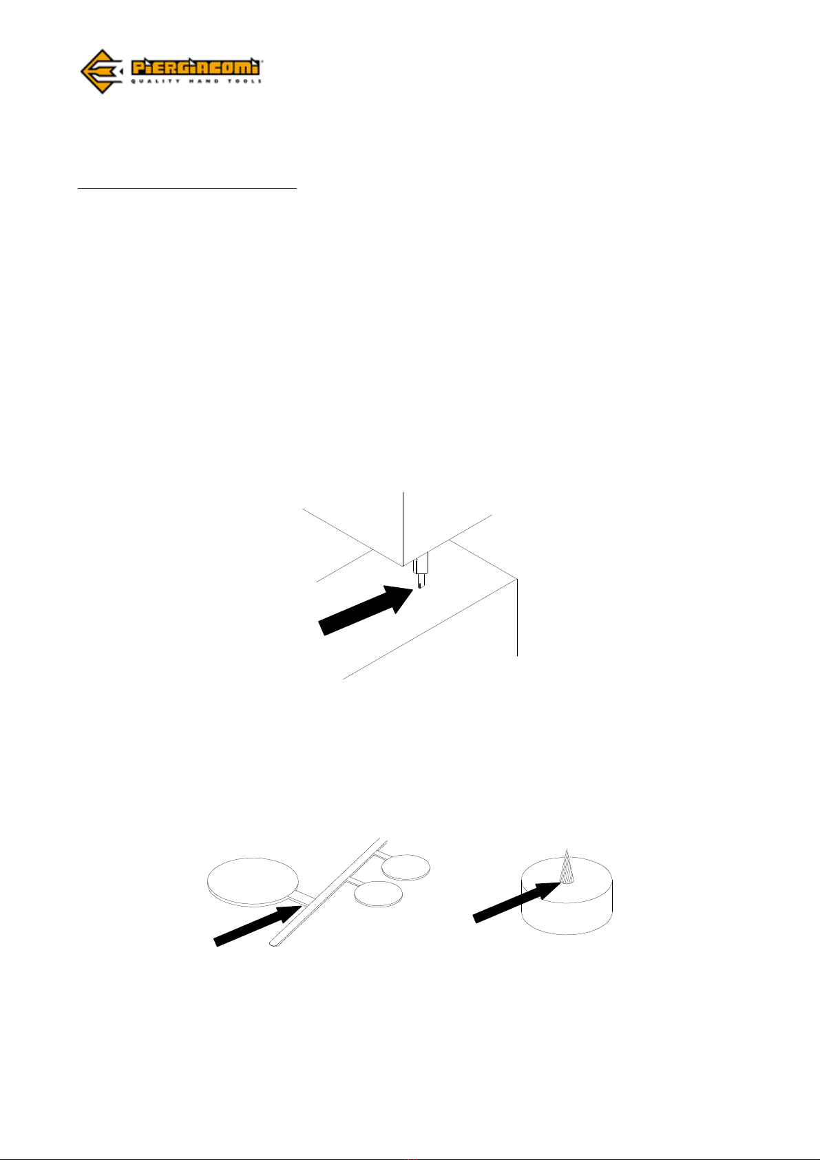
With the wide range of types of tips we enable you to reach normally not much accessible parts as shown
in the diagram.
In the plastic sector, as in that of rubber, cutting the parts without causing damage, when
removing the excess material created by the moulds, is a common problem. –The TR-6000 model
is suitable for cutting small diameters of rubbing material. For cutting bigger diameters,
Piergiacomi developed several solutions, like the TPP-TM-6000.

TPP
INSTRUCTION MANUAL
Page 5 Date rev. 28/05/13
Rev. 07
2.2 TP-6000 - TP-6000-15 - TS-6000
Those who work in the electronics sector frequently have the problem of blocking the components on the
printed circuit board before and during the soldering phase. In order to solve the problem, Piergiacomi
has designed and produced these tools, the TP-6000, which cuts the component leads and bends them
so as to fix them firmly in place to the board. The operator that will later perform the soldering phase will
therefore not have that troublesome problem of components that have been displaced or in the worst
case become loose and fallen off the board.
The TP-6000 or TP-6000-15 proves to be an enormously special tool as it manages to carry out two
functions in one operation and furthermore has the advantages of being a lightweight and reduced costs
pneumatic tool.
This is the basis of our philosophy and our product has been designed to meet both performance and
safety requirements.
3. COMPONENTS PARTS
The main characteristic of the TPP is the possibility to interchange the fix base (body) TPP, as shown in the
Fig. 1 with the several heads or with specific blades for the required work.
Every time a change of works is needed, it’s enough to replace, in a simply and fast way, the upper part
(head) of the tool. See instructions on Chapter .
Example of part number: TPP-TP-6000
VALVE
HOOK
AIR
CONNECTOR
Ø6
LEVER
AIR
CHAMBER
HEAD
HEAD
CUTTING
BLADES
CUTTING
BLADES
Fig. 1

TPP
INSTRUCTION MANUAL
Page 6 Date rev. 28/05/13
Rev. 07
3.1 TPP
3.2 TP-6000 TP-6000-15
Fig. 2
Fig. 3

TPP
INSTRUCTION MANUAL
Page 7 Date rev. 28/05/13
Rev. 07
3.3 TR-6000 TR-6000-V TS-6000
4. BLADE SPECIFICATIONS
The blades are made from grinded & tempered special steel and can be easily replaced, as explained in
Chapters of this manual.
- TP-6000
Cut & Bend blades for blocking the leads of the component on the PCB. (Max cut 1.02 mm)
Fig. 5
–
TP
-
6000
Fig. 4

TPP
INSTRUCTION MANUAL
Page 8 Date rev. 28/05/13
Rev. 07
- TP-6000-15
Cut and Bend Blades for blocking the leads of the component on the PCB, to reach very dense areas.
(Max cut 1.02 mm)
- TR-6000
Blades TR-6000 are supplied standard with 2 typology of cuts (Fig. ):
- CHAMFERED (code TR-6000): permit also to cut harder components & a number of unlimited cuts
without damaging the blades.
- FLUSH (code TR-6000-R): permit to make flush and precise cuts. Suggested in particular where a
absolute accuracy of cut is needed.
Flush cut Chamfered cut
Fig. 6
–
TP
-
6000
-
15
FLUSH
CUT CHAMFERED
CUT
Fig. 7

TPP
INSTRUCTION MANUAL
Page 9 Date rev. 28/05/13
Rev. 07
TR-6000 blade (chamfered cut, Max cut 1.6 mm, Fig. 5) is available in different versions, as shown on our
catalogues:
- TR-6000 R
(Max cut 1.6 mm) with flush cut.
- TR-6000 PR
(Max cut 1.3 mm) with flush cut, but more pointed tips.
- TR-6000 10/13/15
(Max cut 1.6 mm) with flush cut at different height (1.0mm, 1.3mm &
1.5mm) from the surface.
- TR-6000 C
(Max cut 1.6 mm) with shorter and stronger blades.
- TR-6000-V
Flush front 60° angled blades, in order to have the access in difficult points.(Max cut 1.3 mm).
Fig.
8
–
TR
-
6000
SUGGESTED
CUTTING
POINT
Fig. 9
–
TR
-
6000
-
V

TPP
INSTRUCTION MANUAL
Page 10 Date rev. 28/05/13
Rev. 07
- TS-6000
Cut & Press blades, for blocking the leads of the component on the PCB. (Max cut 1.3 mm).
Special blades suitable for your purposes are produced at request!
5. USING THE TOOL
Before using this de ice, read carefully Chapter 1 (Safety Symbols and Rules to
obser e).
Warning!
Always wear protecti e glasses during the use of the tool and do not
work with your fingers close to the blades while mo ing.
Warning!
After using, put de ice in a safety place and disconnect compressed
air supply system.
The tool should be used at the angle shown in the figures with respect to the working surface.
Fig.
11
–
TP
-
6000
Fig. 10
–
TS
-
6000

TPP
INSTRUCTION MANUAL
Page 11 Date rev. 28/05/13
Rev. 07
TR-6000 : The most suggested point for cutting is situated at about 1/3 of the cutting length (see Cap.4
Fig. 8).
Fig.
12
–
TP
-
6000
-
15
Fig.
13
–
TR
-
6000

TPP
INSTRUCTION MANUAL
Page 12 Date rev. 28/05/13
Rev. 07
Fig. 15
–
TS
-
6000
Fig. 14
–
TR
-
6000
-
V

TPP
INSTRUCTION MANUAL
Page 13 Date rev. 28/05/13
Rev. 07
6. HOW TO CHANGE BLADES
6.1 TP-6000
Warning!
During blade remo al, make sure the compressed air supply is shut off.
6.2 TP-6000-15 - TR-6000 - TR-6000-V - TS-6000
Warning!
During blade remo al, make sure the compressed air supply is shut off.
- Use the supplied hexagonal key to
remove the M3 screw on the head and
take out the blade set. ( Fig.16)
- For reassemble the blade, insert the
blade set as indicated on the Fig. 16 and
fasten screw M3.
M3 SCREWS
Fig. 16
- Use the supplied hexagonal key & a
slotted screwdriver to remove the ring
nut and the M4 screw as indicated on
Fig. 1 and take out blades.
- For reassemble the blades follow below
phases:
1) Insert on screw M4 some thread
docking adhesive.
2) Insert blades on the head and fix M4
screw.
3) Hold blades closed by one hand and
fasten the M4 fasten until the blades are
blocked.
4) Fasten the ring nut.
5) Lightly unscrew the M4 screw, until
blades are autonomously open.
Fig. 1
7
–
TR
-
6000
M4
SCREW
RING
NUT

TPP
INSTRUCTION MANUAL
Page 14 Date rev. 28/05/13
Rev. 07
7. SERVICING AND MAINTENANCE
7.1 NORMAL SERVICING
DAILY :
Remove any residual cut material found between the gaps in the head with a compressed air gun.
7.2 SPECIAL SERVICING
EVERY 4 MONTHS :
Lubricate the air seals with vaseline oil following the instructions.
1Remove the compressed air feed tube, put one cubic centimetre of oil in the air
connector as shown in the Fig.18;
2Reconnect the compressed air supply tube to the tool and activate the tool several times to
permit the oil to enter in circulation; if the blade slides freely, the lubrification has been a
success, otherwise repeat stage 1.
HOOK
COMPRESSED AIR
CONNECTOR Ø6
AIR
SILENCER
Fig. 1
8

TPP
INSTRUCTION MANUAL
Page 15 Date rev. 28/05/13
Rev. 07
8. OPTIONAL ACCESSORIES
The following parts can be supplied as optional:
1- Pedal control system + special valve.
9. CHARACTERISTICS
Characteristics:
Air pressure : 6 - bar
Consumption : 3,5 Nl/min
Blade material : Tempered steel
Blade thickness : 6 mm standard
Type of cut : Flush o Chamfered (TR-6000)
Type of bend : 90° (TP-6000) or 30° (TP-6000-15)
Max cut : 1 mm (TP-6000, TP-6000-15)
1.3 mm (TS-6000, TR-6000 PR, TR-6000-V)
1.6mm (TR-6000, TR-6000-C, TR-6000-
10/13/15)
Approximate dimensions: 165 x 35 mm
Weight : 300 g.
TECHNICAL ASSISTANCE OFFICE:
PIERGIACOMI SUD SR
VIA 81A STRADA 3, FRAZ CENTOBUCHI,
63076 MONTEPRANDONE (AP) ITA Y
tel. +39 0735 703 333
fax +39 0735 703 757
COMMERCIAL OFFICE:
PIERGIACOMI SUD SR
Via Gramsci 3 - 60022 Castelfidardo (AN) Italy
tel. +39 071 78678-780 211
fax +39 071 7822 536
www.piergiacomi.com
piergiacomi@piergiacomi.com – in o@piergiacomi.com

TPP
INSTRUCTION MANUAL
Page 16 Date rev. 28/05/13
Rev. 07
DECLARATION OF CONFORMITY
MODELS :
TPP - TR-6000 / TP-6000 / TS 6000
Pneumatic tool to cut electronic components.
DPP
Pneumatic tool for the depaneling of PCBs.
THE TOOLS TPP and DPP ARE CONFORM TO THE ESSENTIAL REQUIREMENTS OF THE FOLLOWING STANDARD OR HARMONIZING
RULES :
DIRECTIVE 98/31/CE
EN 12100-1 Safety of machinery. Basic concepts, general principles for design.
Part 1 Basic terminology, methodology.
EN 12100-2 Safety of machinery. Basic concepts, general principles for design.
Part 2 Technical principles and specifications.
EN 1050 Safety of machinery. Principles for the risk assessment.
MODELS :
SSF-1 / DPB-1
Pneumatic depaneling machine with 1 pneumatic head.
SDP
Pneumatic depaneling machine form 1 to 3 pneumatic heads.
THE MACHINES SSF-1, DPB-1 and SDP ARE CONFORM TO THE ESSENTIAL REQUIREMENTS OF THE FOLLOWING STANDARD OR
HARMONIZING RULES :
DIRECTIVE 98/37/CE
EN 12100-1 Safety of machinery. Basic concepts, general principles for design.
Part 1 Basic terminology, methodology.
EN 12100-2 Safety of machinery. Basic concepts, general principles for design.
Part 2 Technical principles and specifications.
EN 294 Safety of machinery. Safety distances to prevent danger zones being reached by the upper limbs.
EN 1050 Safety of machinery. Principles for the risk assessment.
Monteprandone li 06 - 05 - 2008 Legal Represent
CARINI ENRICO
_
Piergiacomi Sud Srl
head office > Via 81° Strada, 3 – I-630 6 Monteprandone (AP) commercial office > Via Gramsci, 3 – I-60022 Castelfidardo (AN)
tel. +39-0 35- 03333 – fax +39-0 35- 03 5 tel. +39-0 1- 86 8 – fax +39-0 1- 822536
http://www.piergiacomi.com
e-mail piergiacomi@piergiacomi.com
This manual suits for next models
4
Table of contents