Piesia 1037U-3 User manual

Motherboard Interfaces Description
- 1 -
1037U-3 Motherboard
(PCB Rev:1.00)
Manual Version 1.00
2014.04.30

Motherboard Interfaces Description
- 2 -
1 Introduction
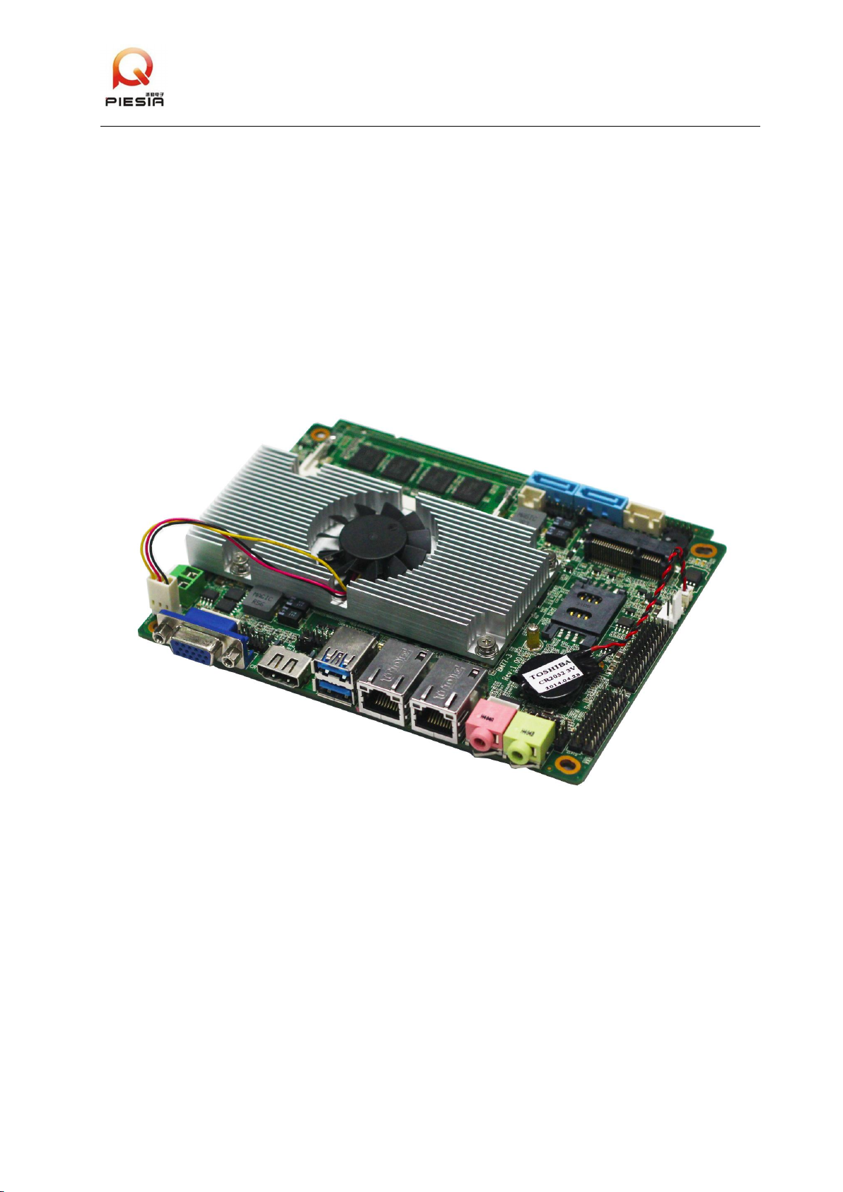
1037U-3 motherboard is our standard 3.5” industrial motherboard.Adopt Intel® HM77/HM76
Express chipsets.Onboard 1037U CPU.
1.1 Main Features
1.1.1 Onboard 1037U CPU.
1.1.2 Onboard 4GB DDR3 memory(1066/1333/1600MHz).
1.1.3 Onboard 2×RTL8111E Gigabit Ethernet controller.
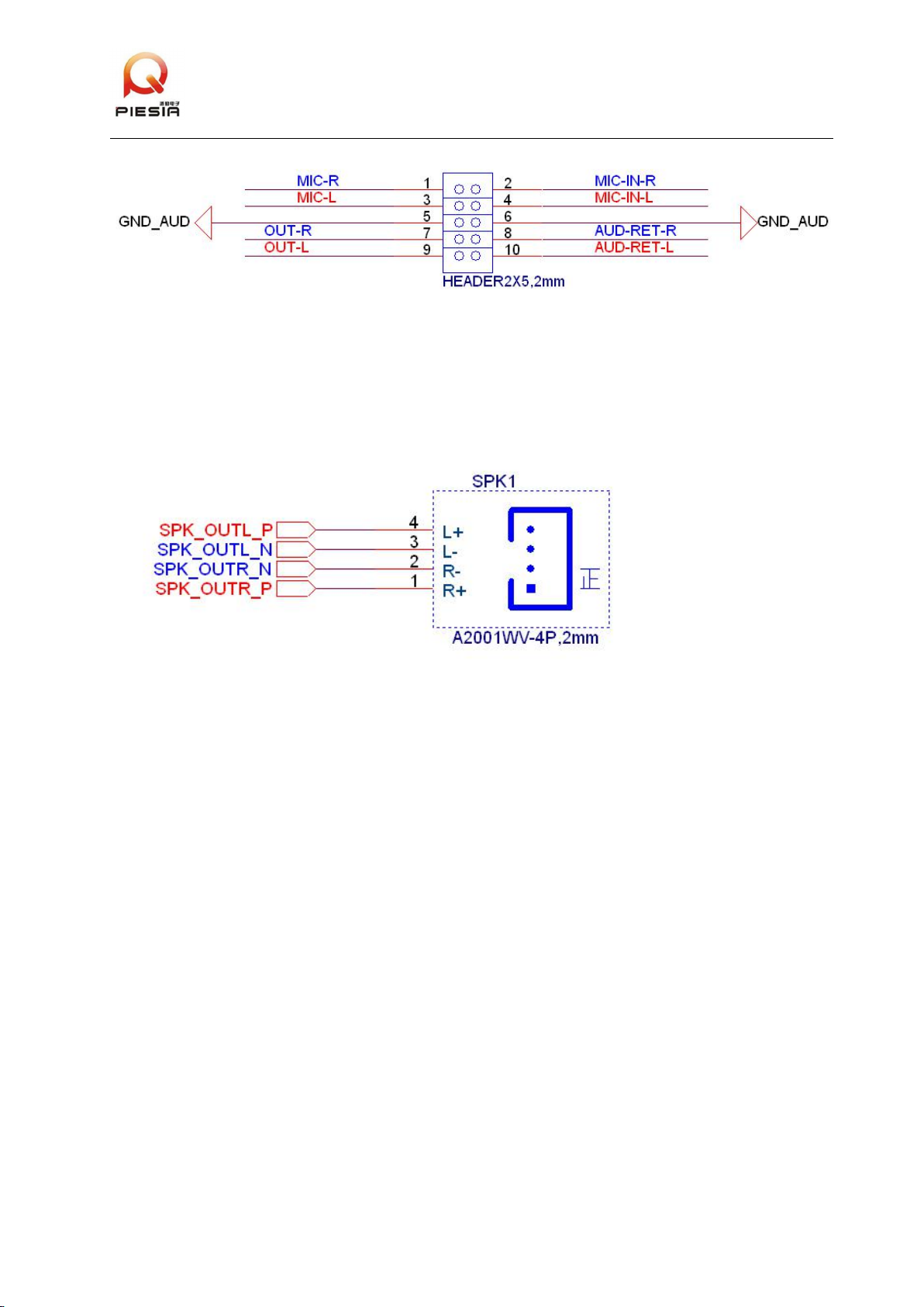
1.1.4 Onboard HD ALC662,provide MIC-IN/LINE-OUT and expansion header.
1.1.5 Onboard dual channel audio power amplifier.Support 6W/8Ω horn for each channel.(optional);
3-pin SPDIF connector.
1.1.6 1×Mini-PCIE socket.
1.1.7 1×Mini-SATA socket.
1.1.8 2×SATAⅡ3Gb/s connector.
1.1.9 2×USB 3.0 ports;6×USB2.0 ports.
1.1.10 Provide 5*RS232 pin header,1*RS485/RS422 pin header.
1.1.11 Support HDMI output.
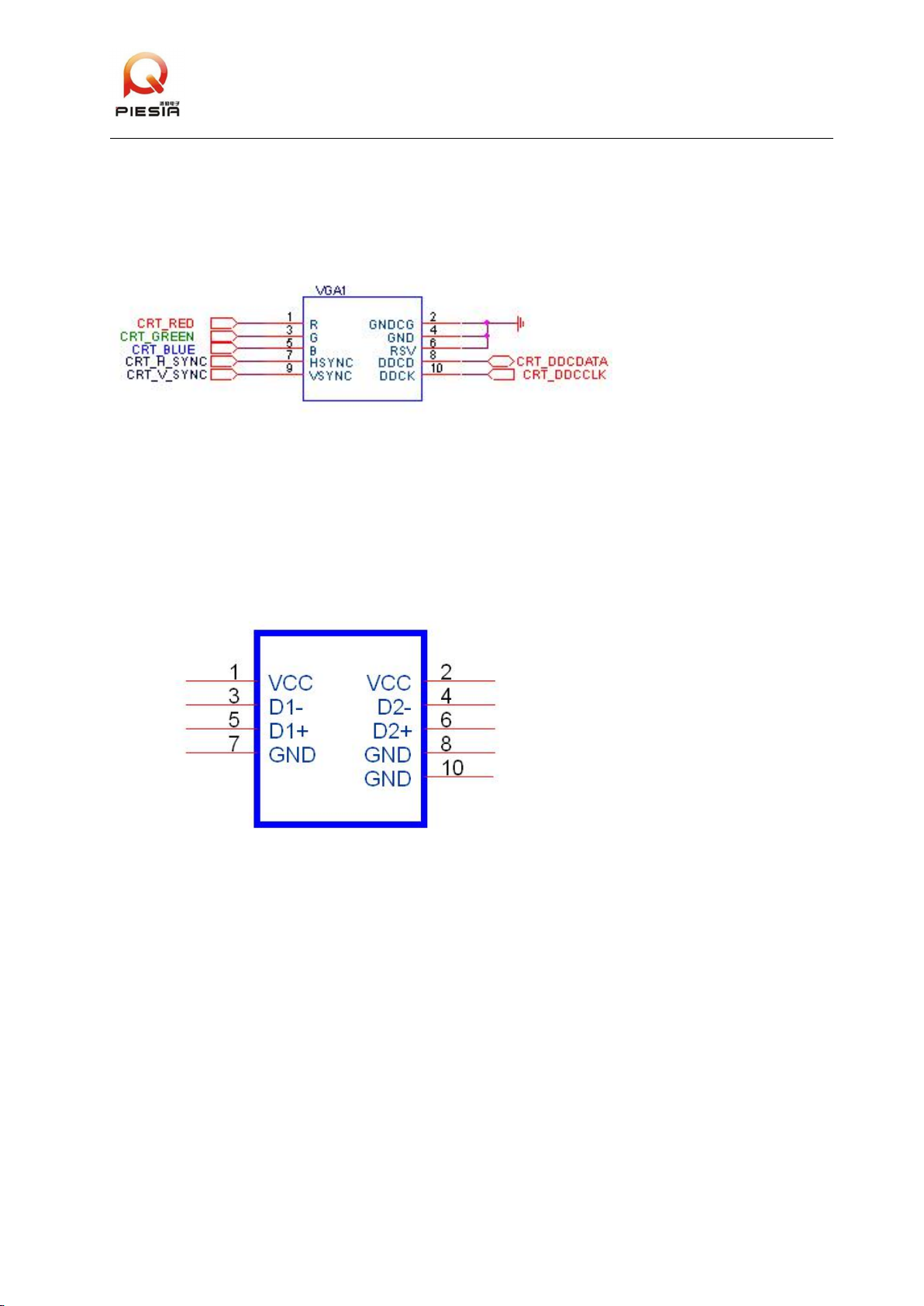
1.1.12 Support RGB &CRT output.
1.1.13 Support dual channel 24bit LVDS output.
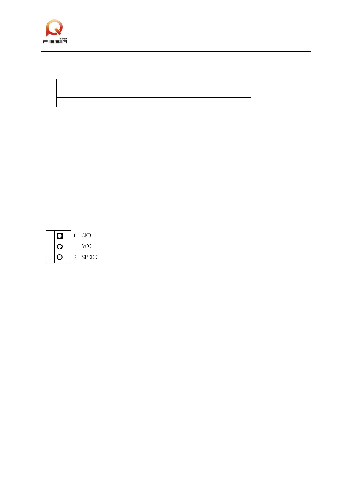
1.1.14 2×3-Pin FAN connectors.
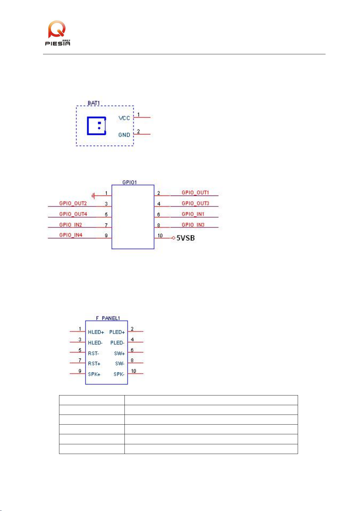
1.1.15 Provide 8bit*GPIO.
1.2 Power Supply
Single input DC power,DC12V(+/-5%).
(If don’t use 12V for the HDD,+/-10%)。
Support AT/ATX starting mode.
1.3 Size
115mm×155mm
1.4 Working Environment
Working Temp:--20°C~70°C (-4°F~158°F)
Storage Temp:-20°C~80°C (-4°F~176° )
10%~90% (non-condensing)

Motherboard Interfaces Description
- 3 -
2 1037U-3 Front side interfaces layout
Motherboard TOP floor layout as below:
Remark:Interfaces in the above picture,Pin 1 are in square shape.
2.1 DC_IN1 & DC_IN2
Motherboard input power connectors, the same application can only choose to plug one input
power.
DC_IN1 adopt ATX_12V interface,as Regular production.
DC _IN2 is DT-126RP-02P Terminal Blocks interface.Please pay attention to the
Positive/Negative electrode of power.
(please input the power,after devices,cables all installed.)

Motherboard Interfaces Description
- 4 -
2.2 CRT1 & VGA1
CRT1 is a standard CRT monitor output interface.
VGA1 is 2×5,2mm expansion header,can not use at the same time.
2.3 HDMI1
HDMI1 is standard HDMI output interface.
2.4 USB01、USB23、USB45 & USB89
All are USB interfaces,support USB 1.0/1.1/2.0/3.0 devices.
USB45 is standard USB Type A interface with USB3.0;
USB01、USB23、USB89 2×5,2mm are expansion headers with USB2.0,definition as below:
2.5 LAN1 & LAN2
10/100/1000 M LAN is standard RJ45 port,chipset is Realtek RTL8111E.Support Wake-On-Lan
and PXE booting.
2.6 MIC_IN、LINE_OUT and AUDIO1
MIC_IN is Microphone input port,adopt general connector.
LINE_OUT is audio output port,adopt general connector.
F_AUDIO is 2×5,2mm expansion header,definition as below:

Motherboard Interfaces Description
- 5 -
(1:If AUDIO1 have not connect with the AUDIO Cable in the front panel,have to catch Jumper
1-2、3-4、7-8、9-10.
(2:1、3、5、7、9 pins are the output signal for front panel;2、4、6、8、10 pins are return signal.
2.7 Audio power amplifier output interface SPK1(optional)
Dual channel power amplifier,support 6W/8Ω horn for each channel.Definition as below:
Attention:The front panel AUDIO1 has priority.MIC_IN、LINE_OUT can not work,if the front panel
AUDIO1 connected.The SPK1 can not output,if the LINE_OUT connected.

Motherboard Interfaces Description
- 6 -
2.8 SPDIF(optional)
Adopt 1×3,2.54mm expansion header,interface optional.
Pin1----5V;
Pin2----SPDIF;
Pin3----GND。
2.9 LVDS1
24bit dual CH LVDS interface,adopt 2×15,2mm pin header,definition as below:
VCC_LVDS is the power for screen,LCD_3V_5V or LCD_12V ,choose through the jumper.
2.10 LCD_3V_5V & LCD_12V
LVDS1 power:VCC_LVDS power selection:
selection mode
VCC_LVDS Voltage
LCD_3V_5V(1-2)、LCD_12V(Open)
3.3V(default setting)
LCD_3V_5V(2-3)、LCD_12V(Open)
5V
LCD_3V_5V(Open)、LCD_12V(Close)
12V
2.10 LVDS_P1
LVDS screen back light interface,adopt CJT A2001WR-6P-1connector or other compatible
connector.Definition as below:
LVDS_P
LVDS_P definition
1
Ground
2
Ground
3
Back light luminance control
4
Back light-ON
5
12V
6
12V

Motherboard Interfaces Description
- 7 -
2.12 COM1、COM4、COM5
RSR232 pin header,adopt 2×5,2mm pin,Pin10 power is 5V.
2.13 COM2、COM6
RSR232 pin header,adopt 2×5,2mm pin,Pin10 power is 12V.
2.14 COM3
RS485/R422 can use the same interface,adopt 2×3,2mm pin header,must comply with the
setting and type of COM3 in CMOS.Definition as below:
2.15 Parallel Port LPT
Adopt 13×2,2mm pin header.Definition as below:

Motherboard Interfaces Description
- 8 -
2.16 SATA1、SATA2
Standard SATA device interface,support SATAⅡ(3Gb/s)and below.
SATA2 can be change to a bend 90 degree SATA connector,suitable for low height structure.
2.17 HD_P1、HD_P2
2*SATA power interface,adopt CJT A2501WV-4P,A2501WV-2P device or other compatible
devices,definition as below:
HD_P2 with 2 more pin than HD_P1,bring in 12V power for the hard disk of commercial
computer.The 12V is coming from DC power.If there is a big voltage deviation with the DC
power,please do not choose a hard disk with voltage 12V/5V.
2.18 RTC1
RTC1 is RTC clear jumper line,adopt 1×2,2mm pin,definition as below:
RTC1
Function introduction
Close
Clear RTC CMOS
Open
default setting

Motherboard Interfaces Description
- 9 -
2.19 BAT1
Battery interface,for battery changing.Adopt CJT A1251WV-2P connector or other compatible
connector.
2.20 GPIO1
Spare GPIO interface,adopt 2×5,2mm pin,definition as below:
(The I/O features of GPIO can be amend through BIOS.)
2.21 FP1
Control panel interfaces,adopt 2×5,2mm pin,integrated HDD_LED、PWR_LED、on/off、reset
switch、SPEAKER function.Pin definition as below:。
F_PANEL1
Pin Definition
1,3
Hard disk access lamp positive and negative signal pins.
2,4
Main power indicator light positive and negative signal pins.
5,7
Motherboard reset positive and negative signal pins.
6,8
Motherboard on/off positive and negative signal pins.
9,10
Spare buzzer connector.

Motherboard Interfaces Description
- 10 -
2.22 JP1
AT starting mode jumper line.When you choose “Close” , the DC power plug,then the board
electrify at the same time.
PS_ON
Starting Mode Selection
Close
AT power starting mode
Open
ATX power starting mode
Remark:JP1 & FP1 combine to a pin header:2x6、2mm.The JP1 function can be lead to the
Front/Rear panel of the chassis.
2.23 MPCIE1
MPCIE1 is standard Mini-PCIE socket,suit for full-size card.The half-size card Mini-PCIE
card,must be fixed with a extended card.
2.24 SIM1
MPCIE1 affiliated SIM card slot,for 3G function.
2.25 CPU_FAN1、SYS_FAN1
FAN interface support maximum current 0.3A,definition as below:
CPU fan connector,rotational speed adjust automatically.The maximum voltage is the power
input voltage.Please choose a suitable fan,when the input voltage is higher.SYS fan does not support
adjust automatically.

Motherboard Interfaces Description
- 11 -
3 1037U-3 Rear Side Interface Layout
Motherboard rear side layout as below:
3.1 M_SATA
Support Mini-SATA SSD.This motherboard support most of the large company’s Mini-SATA
card.For detailed informations.please contact with our salesman and technician.
Table of contents
Other Piesia Motherboard manuals