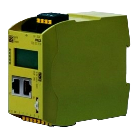
Pilz PSS SB DI16 User manual

The spirit of safety.
Programmable Safety Systems
PSS-Range
PSS SB DI16
Operating Manual
Item No. 20 085-07

All rights to this documentation are reserved by Pilz GmbH & Co. KG. Copies may be made
for internal purposes.
Suggestions and comments for improving this documentation ill be gratefully received.
The names of products, goods and technologies used in this documentation are registered
trademarks of the respective companies. Automation Workbench
®
, Pilz
®
, PIT
®
, PMI
®
,
PNOZ
®
, Primo
®
, PSS
®
, SafetyBUS p
®
are registered trademarks of Pilz GmbH & Co. KG.

Operating Manual 1
Contents
Introduction 2
Validity of the documentation 2
Overview 2
Intended use 3
System requirements 3
CPU versions 3
System software versions 3
Functions 5
Inputs 5
Detecting signals at the inputs 5
Signal change behaviour 6
Test pulse outputs/24 VDC terminals 7
Schematic internal wiring diagram 7
Operation of the module on SafetyBUS p 9
Display elements 10
Installation 11
Commissioning 12
Recommissioning 12
Faults 12
Module configuration 13
Technical details 14
Changes in the documentation 16
PSS SB DI16

PSS SB DI16
2Operating Manual
Introduction
This shortform explains the function and operation of the decentralised
input/output module PSS SB DI16.
The documentation is intended for instruction and should be retained for
future reference.
Validity of the documentation
The PSS SB DI16 documentation is valid from Version 2.1 onwards. It is
valid until new documentation is released. The latest documentation is
supplied with the unit.
Overview
The module provides 16 digital inputs and 4 dedicated test pulse outputs.
The inputs are suitable for connecting single or dual-channel safety-
related input devices, with or without test pulses. Inputs can be assigned
to two I/O-Groups in SafetyBUS p.
Each test pulse output has 4 terminals, which can also be configured in
pairs as 24 VDC terminals.
The PSS SB DI16 requires a 24 V supply, which feeds both the module
electronics and the dedicated test pulse outputs.
The module is galvanically isolated from SafetyBUS p via optocouplers.
NOTICE
Before installing the module you should read and consider the “PSS SB
DI16 Installation Manual” and the “SafetyBUS p System Manual”.

Operating Manual 3
Intended use
The PSS SB DI16 is a decentralised input module which has been
designed for use as an “Input/Output Device”on SafetyBUS p.
System requirements
CPU versions
Before using the module on SafetyBUS p you must ensure that all the
safety systems accessing the module can in fact support it. This means
that all safety systems with Logic Device functionality which are assigned
to I/O-Group(s) on the PSS SB DI16, and the safety system with Manage-
ment Device functionality, must all support the module.
The PSS SB DI16 is supported by all SafetyBUS p-compatible safety
systems in the PSS-range, although on the PSS-types listed below, only
from the version number stated:
• PSS SB CPU from Version 1.3
• PSS1 SB CPU from Version 1.3
• PSS SB 3006 IBS-S PCP from Version 1.2
• PSS SB 3056 from Version 1.2
System software versions
The following system software is required in order to configure the module:
• PSS WIN-PRO from version 1.0.0

PSS SB DI16
4Operating Manual
0
3
6
9
x 1
0
3
6
9
x 10
SB Address
1 = Supply
2 = Supply
3 = Ground
4 = Ground
^
^
^
^
Power
1234
Supply
I/O-Group
Device
SB active
PSS SB DI16
301 130
Group
I0I1I2I3I4I5I6I7I8I9I10 I11 I12 I13 I14 I15
1... X5 ...4
Ground
1... X6 ...8
I0I1I2I3I4I5I6I71... X7 ...8
I8I9I10 I11 I12 I13 I14 I15
1... Tx / 24 V DC X3 ...8
T0T1T2T31... Tx / 24 V DC X4 ...8
T0T1T2T3
1... Ground X2 ...8
1...
Power
X1 ...4
X0
119
1
3
2
4
5
6 7
810 11
7
1: Switch for setting the device address on SafetyBUS p
2: Labelling strip for the inputs
3: SafetyBUS p interface
4: LEDs for operating status and supply voltage
5: Status LEDs for the inputs
6: Terminal block for “Ground”
7: Connection terminal for inputs
8: Connection terminal for the functional earth
9: Connection terminal for the supply voltage
10: Terminal block for “Ground”
11: Terminal block for dedicated test pulses or 24 VDC
Fig. 1: Test pulse and output configuration

Operating Manual 5
Functions
Inputs
The inputs are suitable for connecting single and dual-channel input
devices, with or without test pulses.
Input signals must show a “High” of 24 VDC (+15 ... +30 VDC) and a “Low”
of 0 VDC (-3 ... +5 VDC). All inputs have input filters.
Input status is transmitted to the CPU on the PSS master via SafetyBUS p.
Yellow LEDs indicate the status of the inputs. An LED lights up as soon as
a “1” signal is present at the input.
Diagnostic circuitry checks the function of the inputs, including the input
filter. If an error occurs, all the outputs in the affected I/O group will be
switched off and the I/O-group will switch to a STOP condition. An error
telegram will then be stored on SafetyBUS p and the error will entered in
the PSS SB DI16 error buffer.
Where test pulses are not used, inputs with single-channel input devices
can be used in applications up to and including category 2 in accordance
with EN 954-1; in the case of dual-channel input devices, this extends to
category 3 applications. The device should be suitably wired to eliminate
the risk of a short circuit in the external wiring between the different inputs
and a short to the “Supply”.
Test pulses must be used for applications with single-channel input
devices above category 2 and applications with dual-channel input
devices above category 3.
Connection diagrams can be found in the “PSS SB DI16 Installation
Manual”.
Inputs can be allocated to two I/O-Groups. For further information please
refer to “Operation of the module on SafetyBUS p”.
Detecting signals at the inputs
To guarantee that a signal („0“-Signal or „1“-Signal“) is detected at an
input, it must be present for a certain period of time. This time must be
longer than the Event Timeout configured in the system software PSS
WIN-PRO. The presence of a signal will trigger a corresponding Event
Telegram.

PSS SB DI16
6Operating Manual
The presence of a signal (“0” or “1” signal) will be ignored if it does not
exceed the pulse suppression time of 300 µs. In this case, no Event
Telegram will be sent.
Signal change behaviour
If a signal change occurs at an input, the module will send an Event
Telegram. The module must then wait for the acknowledgement telegram
(ACK) from the Master-LD before it can send a new Event Telegram.
If another signal change occurs while the module is waiting for the
acknowledgement telegram, the module's response will depend on the
configured signal change behaviour.
Two behaviour modes may be defined:
• “Default”:
The signal change is not registered
• “Fast”:
Each signal change is stored in a FIFO telegram buffer. If the
acknowledgement telegram arrives, the module will send an Event
Telegram from the FIFO telegram buffer for each signal change
detected.
"1"-Signal
"0"-Signal
t
1
t
1
t
t
2
U
t1: Pulse length for guaranteed signal detection for “1” or “0” signals
(> Event Timeout)
t2: Max. pulse length for pulse suppression on “1” or “0” signals
(300 µs)
Fig. 2: Detecting signals at the inputs

Operating Manual 7
Test pulse outputs/24 VDC terminals
The four test pulse outputs T0to T3are used exclusively for test pulses or
as 24 VDC terminals. The test pulses are suitable for testing the wiring of
input devices. Only inputs which operate in accordance with the zero
signal principle (on switching off) are permitted for safety-related
applications.
Test pulses are allocated to inputs via the configurator in the programming
device.
Each test pulse output has four terminals, which are divided into two
terminal pairs. If a terminal pair is not being used for a test pulse it can be
used instead as a 24 VDC terminal. The use of terminal pairs is also
established via the configurator in the programming device. All terminals
are configured as 24 VDC terminals in the default setting.
Each terminal pair has a maximum load capacity of 0.5 A, irrespective of
its use.
Schematic internal wiring diagram
The diagram on page 8 shows a schematic internal wiring diagram of the
PSS SB DI16, showing galvanic isolation from SafetyBUS p, etc.

PSS SB DI16
8Operating Manual
T
01
0
24 V DC
1
0
T
3
I
0
5 V
24 V
DC
DC
CPU
(2-channel)
Test
I
15
Test
I
15
I
14
I
13
I
12
I
11
I
10
I
9
I
8
I
7
I
6
I
2
I
4
I
3
I
2
I
1
I
0
T
3
/ 24 V DC
T
3
/ 24 V DC
T
2
/ 24 V DC
T
2
/ 24 V DC
Ground
Ground
Supply
Supply
Ground
T
1
/ 24 V DC
T
1
/ 24 V DC
T
0
/ 24 V DC
T
0
/ 24 V DC
1
0
24 V DC
1
0
T
01
0
24 V DC
1
0
T
31
0
24 V DC
1
0
T
3
/ 24 V DC
T
3
/ 24 V DC
T
2
/ 24 V DC
T
2
/ 24 V DC
T
1
/ 24 V DC
T
1
/ 24 V DC
T
0
/ 24 V DC
T
0
/ 24 V DC
3,3 nF 2,4 M
6,6 nF
Fig. 3: Schematic internal wiring diagram of the PSS SB DI16

Operating Manual 9
Operation of the module on SafetyBUS p
The module is connected to SafetyBUS p via a male 9-pin D-Sub
connector. Fibre-optic couplers from Pilz (like PSS SB SUB-D F0) can be
connected to the SafetyBUS p interface.
To enable the module to operate on SafetyBUS p, it must be given the
device address set via the configurator in the system software. Device
addresses 32dec ... 95dec are permitted if you are using the device in
conjunction with a Pilz PSS.
The configurator in the system software is also used to establish which I/O
groups the device belongs to.
The module can be divided into Section A and Section B. Section A and
Section B may belong to different I/O-Groups. The module itself can either
have Section A only, Section B only, or both Section A and Section B.
Input may be assigned to either section, as required.
The I/O addresses which the PSS master uses to address the inputs are
established according to their membership of Section A or B and the
device address.
Under the device address in the process I/O image of the PSS master,
inputs from Section A are addressed as slot number and bit number 0 ...
15. Inputs from Section B are addressed under the device address as slot
number and bit number 16 ... 31; this corresponds to an offset of 16 in the
bit number.
For example, if input I6from Section A is reconfigured to Section B, the
address will change from x.6 to x.22.
Example: Device address is 36
Input Section Address Input Section Address
I0A E36.00 I8A E36.08
I1A E36.01 I9A E36.09
I2B E36.18 I10 A E36.10
I3B E36.19 I11 A E36.11
I4B E36.20 I12 A E36.12
I5A E36.05 I13 B E36.29
I6A E36.06 I14 B E36.30
I7A E36.07 I15 B E36.31

PSS SB DI16
10 Operating Manual
Display elements
LEDs for status display
Each input is assigned an LED for status display.
If the input is high, the corresponding LED will light. If it goes low, the LED
will go out.
LED “Supply”
Indicates that the supply is present.
LED “Device”
This dual-coloured LED indicates the status of the device.
• Red: a device error has occurred. The device error may affect one or
both of the I/O groups configured on the module.
• Flashing red: a periphery error has occurred.
• Green: the module is operating without error.
• LED off: a system error is preventing the module from starting up.
LED “SB active”
Indicates a connection between the module and the management device.
• Green: Successfully connected to management device
• LED off: no connection to SafetyBUS p (faulty wiring or management
device not in operation)
• LED flashing: Connection made to SafetyBUS p, but the management
device does not recognise the module (invalid device address or
configuration)
LED “I/O Group”
Indicates the status of the I/O groups configured on the module.
• Green: all the I/O groups configured on the module have “RUN” status
• LED off: all the I/O groups configured on the module have “STOP” status
• LED flashes: one of the I/O groups configured on the module has
“STOP” status.

Operating Manual 11
Installation
Dimensions in mm ("):
H x W x D: 140 x 170 x 65 (5.51 x 6.69 x 2.56)
The module can be attached to a 35 mm DIN-rail (top hat rail) or can be
screwed on to mounting plate using fixing bolts (order no. 311 068).
To affix the module on to a mounting plate, drill 2 x M4 holes (internal
thread) in the mounting plate, as shown in the above diagram (tolerance:
± 0.2 mm/0.01").
Free space for rail-
mounting and for
ventilation
Fig. 4: Installing the PSS SB DI16, dimensions stated in mm (")
0
3
6
9
x 1
0
3
6
9
x 10
SB Address
1 = Supply
2 = Supply
3 = Ground
4 = Ground
^
^
^
^
Power
1234
Supply
I/O-Group
Device
SB active
PSS SB DI16
301 130
Group
I
0
I
1
I
2
I
3
I
4
I
5
I
6
I
7
I
8
I
9
I
10
I
11
I
12
I
13
I
14
I
15
1... X5 ...4
Ground
1... X6 ...8
I
0
I
1
I
2
I
3
I
4
I
5
I
6
I
7
1... X7 ...8
I
8
I
9
I
10
I
11
I
12
I
13
I
14
I
15
1... Tx / 24 V DC X3 ...8
T
0
T
1
T
2
T
3
1... Tx / 24 V DC X4 ...8
T
0
T
1
T
2
T
3
1... Ground X2 ...8
1...
Power
X1 ...4
X0
1
160 (6.30")
65 (2.56")
15
(0.59")
60 (2.36")
Recommended
free space for
wiring

PSS SB DI16
12 Operating Manual
Commissioning
General guidelines are given below, but you should always refer to the
“PSS SB DI16 Installation Manual” (this is part of the “Safety BUS p”
System Manual and is also enclosed with every Safety BUS p-compatible
PSS):
• Install the module
INFORMATION
If the module is attached to an earthed DIN-rail, this will automatically
cover the module's functional earth requirements.
• Wire the inputs and test pulse outputs
• Connect the module to SafetyBUS p and set the device address
• Connect the supply voltage.
Recommissioning
NOTICE
If the device has to be recommissioned you may experience errors when
inserting the terminal blocks, as these are not position-coded.
To ensure such errors are eliminated, always carry out a function test
when recommissioning.
Faults
If a module is defective or there is a wiring error, all the outputs in the
affected I/O group will be switched off and the I/O-group will switch to a
STOP condition. An error telegram will then be stored on SafetyBUS p
and the error will entered in the PSS SB DI16 error buffer.
An error message will appear on the PSS master’s display. The error
stack display in the programming device can be used to locate the error
(see “SafetyBUS p System Description”).

Operating Manual 13
Module configuration
The procedure for configuring SafetyBUS p and the PSS SB DI16 module
is described in the online help of the PSS WIN-PRO system software.

PSS SB DI16
14 Operating Manual
Technical details
Electrical data
Supply voltage 24 V DC
Tolerance 20 ... 30 V DC including residual ripple
of max. ± 1.2 V
Power consumtion "Supply": 90 mA plus load currents
from the test pulse outputs and load currents
for fibre-optic couplers (25 mA per fibre-
optic coupler);
Galvanic isolation Yes (optocoupler), between inputs and
SafetyBUS p
Connection type Spring-loaded terminals or plug-in screw
connectors
SafetyBUS p
Transmission rate Max. 500 kBit/s
Cable runs Max. 3500 m
Transmission type Two-wire differential (3-core cable)
Fibre-optic cabale via fibre-optic coupler
Connection 9-pin D-Sub connector
Digital inputs
Number of inputs 16
Potential isolation Yes, between inputs and SafetyBUS p
“1” level (high) +15 ... +30 VDC
“0” level (low) -3 ... +5 VDC
Input current Typ. 6 mA
Input delay < 1 ms
Pulse suppression < 300 µs
Status indicator Yellow LED
Dedicated test pulses
Number 4 (4 terminals per test pulse, can be
configured in pairs as test pulse or 24 VDC
terminals)
Output current at “1” signal Max. 0.5 A per terminal
Total load capacity Max. 0.5 A per terminal pair
Cable length between test pulse output and input
max. 200 m

Operating Manual 15
ENGLISH
Environmental data
Protection type (EN 60529) IP20
Mounting position Any
Ambient temperature
(EN 60068-2-14) 0 ... 60 °C
Storage temp. (EN 60068-2-1/-2) -25 ... +70 °C
Climatic suitability
(EN 60068-2-78) Max. 95 % r. h.
Condensation Not permitted
Vibration (EN 60068-2-6) Frequency range: 10 ... 150 Hz
max. 1g
Vibration resistance (EN 60068-2-27) 15g, 11 ms
EMC EN 50082-2
EN 55011 A
Mechanical data
Weight 460 g
Dimensions (H x W x D) 140 x 170 x 65 mm
The names of products, goods and technologies are trademarks of the respective companies.
The version of the standards current at 2002-03 shall apply.

PSS SB DI16
16 Operating Manual
Changes in the documentation
Changes from version I to version II
Old New Change
p. no. p. no.
6 6 Internal wiring diagram was amended.
Changes from version II to version III
Old New Change
p. no. p. no.
--- 4 New: section “Detecting signals at the inputs”
16 16 New: version information under “Transmission rate”
Changes from version IV to version III
Old New Change
p. no. p. no.
4 4 Pulse length for guaranteed signal detection >
Event Timeout
Changes from version V to version IV
Old New Change
p. no. p. no.
- 2 Validity of the documentation
- 6 Signal change behaviour
- 18 Signal change behaviour
19 19 Power consumtion
19 19 fibre-optic couplers can now be connected to the
SafetyBUS p interface

Operating Manual 17
Changes from version VI to version V
Old New Change
p. no. p. no.
5 5 Pulse suppression now 300 µs
6 6 Pulse suppression now 300 µs
19 19 New: Pulse suppression in Technical details
Changes in version 20 085-07
Old New Change
p. no. p. no.
Norms updated
- 3 New: section "System software versions"
6 - INFO deleted
13-18 13 Module configuration
15 15 Technical details was amended
- 15 New: "The version of the standards current at 2002-03
shall apply"

PSS SB DI16
18 Operating Manual
Notes
This manual suits for next models
1
Table of contents
Other Pilz Network Hardware manuals
Popular Network Hardware manuals by other brands

Atlantis Land
Atlantis Land DiskMaster NAS G303S manual

Matrix Switch Corporation
Matrix Switch Corporation MSC-HD84AAL product manual

TP-Link
TP-Link TL-PA4010 Quick installation guide

Asante
Asante AsanteTalk installation guide

Wisenet
Wisenet XRN-6410RB2 user manual

Verilink
Verilink WANsuite 6450 Reference manual