Pilz SDD ES ETH User manual

SDD ES ETH
Operating Manual-1003824-EN-06
}PSEN sensor technology

Preface
This document is the original document.
All rights to this documentation are reserved by Pilz GmbH & Co. KG. Copies may be made
for the user's internal purposes. Suggestions and comments for improving this documenta-
tion will be gratefully received.
Source code from third-party manufacturers or open source software has been used for
some components. The relevant licence information is available on the Internet on the Pilz
homepage.
Pilz®, PIT®, PMI®, PNOZ®, Primo®, PSEN®, PSS®, PVIS®, SafetyBUS p®,
SafetyEYE®, SafetyNET p®, the spirit of safety® are registered and protected trademarks
of Pilz GmbH & Co. KG in some countries.
SD means Secure Digital

Contents
Operating Manual SDD ES ETH
1003824-EN-06 | 3
Introduction ............................................................................................................................ 5
Validity of documentation.......................................................................................................... 5
Using the documentation .......................................................................................................... 5
Definition of symbols................................................................................................................. 5
Overview ................................................................................................................................. 6
Scope of supply ........................................................................................................................ 6
Unit features ............................................................................................................................. 6
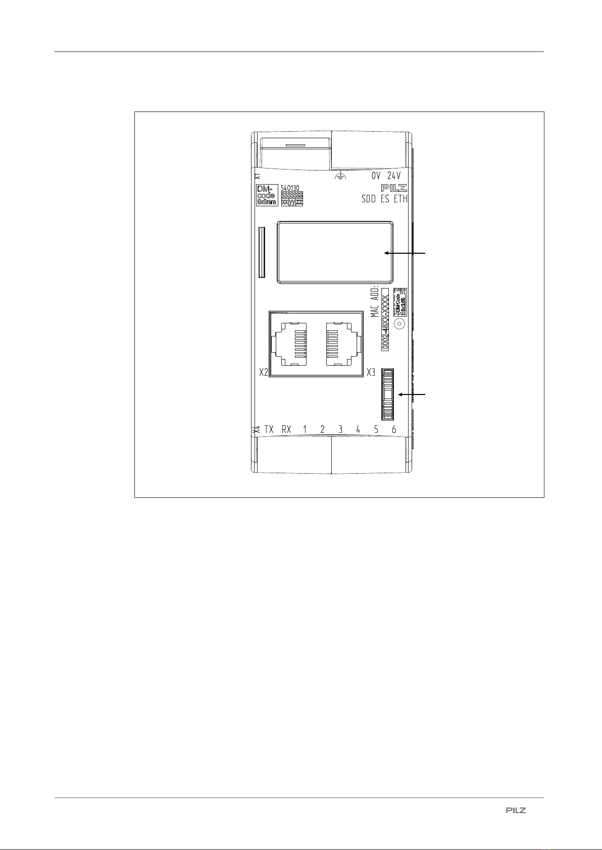
Front view ................................................................................................................................. 7
Safety ...................................................................................................................................... 8
Intended use ............................................................................................................................. 8
Safety regulations ..................................................................................................................... 9
Additional documents that apply............................................................................................... 9
Use of qualified personnel ........................................................................................................ 9
Warranty and liability ................................................................................................................ 9
Disposal .................................................................................................................................... 9
Security ................................................................................................................................... 10
Implemented security measures............................................................................................... 10
Required security measures ..................................................................................................... 10
Function description ............................................................................................................. 11
Operation .................................................................................................................................. 11
Data structure ........................................................................................................................... 12
Block diagram ........................................................................................................................... 12
Installation .............................................................................................................................. 13
Commissioning ...................................................................................................................... 13
General wiring guidelines ......................................................................................................... 13
Ethernet interfaces.................................................................................................................... 13
RJ45 interfaces ("Ethernet") ..................................................................................................... 13
Requirements of the connection cable and connector.............................................................. 14
Interface configuration .............................................................................................................. 14
RJ45 connection cable ............................................................................................................. 14
Process data exchange ............................................................................................................ 15
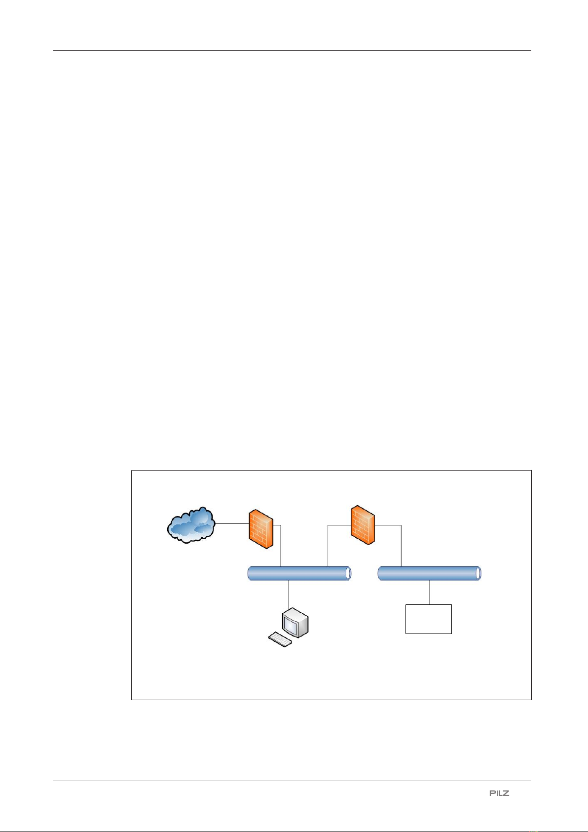
System structure....................................................................................................................... 16
Set IP address .......................................................................................................................... 16
Operation ................................................................................................................................ 17
Display ...................................................................................................................................... 18
Structure ................................................................................................................................... 18
Operate menu........................................................................................................................... 19
Menu structure.......................................................................................................................... 19
Menu settings ........................................................................................................................... 20
Device History menu................................................................................................................. 21
Device Info menu...................................................................................................................... 22

Contents
Operating Manual SDD ES ETH
1003824-EN-06 | 4
Device Event menu................................................................................................................... 23
Web server ............................................................................................................................... 23
Events of Safety Device Diagnostics ........................................................................................ 28
Dimensions in mm ................................................................................................................. 30
Tecnical details ...................................................................................................................... 32
Supplementary data .............................................................................................................. 34
Network data............................................................................................................................. 34
Order reference ...................................................................................................................... 34
Product ..................................................................................................................................... 34
Accessories .............................................................................................................................. 34
EC declaration of conformity ................................................................................................ 35

SDD ES ETH
Operating Manual SDD ES ETH
1003824-EN-06 | 5
Introduction
Validity of documentation
This documentation is valid for the product SDD ES ETH. It is valid until new documenta-
tion is published.
This operating manual explains the function and operation, describes the installation and
provides guidelines on how to connect the product.
Using the documentation
This document is intended for instruction. Only install and commission the product if you
have read and understood this document. The document should be retained for future ref-
erence.
Definition of symbols
Information that is particularly important is identified as follows:
DANGER!
This warning must be heeded! It warns of a hazardous situation that poses
an immediate threat of serious injury and death and indicates preventive
measures that can be taken.
WARNING!
This warning must be heeded! It warns of a hazardous situation that could
lead to serious injury and death and indicates preventive measures that can
be taken.
CAUTION!
This refers to a hazard that can lead to a less serious or minor injury plus
material damage, and also provides information on preventive measures
that can be taken.
NOTICE
This describes a situation in which the product or devices could be dam-
aged and also provides information on preventive measures that can be
taken. It also highlights areas within the text that are of particular import-
ance.

SDD ES ETH
Operating Manual SDD ES ETH
1003824-EN-06 | 6
INFORMATION
This gives advice on applications and provides information on special fea-
tures.
Overview
Scope of supply
}Fieldbus module SDD ES ETH
Unit features
SDD ES ETH is an active subscriber (Master) of Safety Device Diagnostics
}Backlit display
}LEDs for
– Supply voltage
– Fieldbus interface
– Safety states and diagnostic information for the safety devices
– Error
}Multifunction switch for menu control
}Plug-in connection terminals:
Either spring-loaded terminal or screw terminal available as an accessory (see Order ref-
erences for accessories).
}6 contacts that can be used as input contacts and/or output contacts (GPIO)

SDD ES ETH
Operating Manual SDD ES ETH
1003824-EN-06 | 7
Front view
[2]
[1]
[3]
[5]
[4]
[6]
[7]
Legend
X1 }Supply voltage 0V, 24V
}Functional earth
X2/X3 Ethernet interfaces
X4 }TX: Output for connecting the signal input of the safety devices
}RX: Input for connecting the signal output of the safety devices
}1 – 6: Configurable inputs/outputs for connecting signal inputs/out-
puts from additional devices (not incorporated in safety device dia-
gnostics)
[1] LED Power
[2] LED ModbusTCP
[3] LED Devices
[4] LED Start up
[5] LED Fault
[6] Display
[7] Multifunction switch

SDD ES ETH
Operating Manual SDD ES ETH
1003824-EN-06 | 8
Safety
Intended use
The SDD ES ETH is used for communication between connected safety devices and the
Modbus/TCP. The Modbus/TCP is designed for data exchange at field level. The SDD ES
ETH operates as the Server; a connected control system operates as the Client.
Application of the product SDD ES ETH:
}Evaluate and display diagnostic data and status information from safety devices
}Connect safety devices and Modbus/TCP
}Processing and display of safety device data
}Transfer diagnostic data and status information from the safety devices to Modbus/TCP
Appropriate safety devices are listed in the document "System Description Safety Device
Diagnostics".
The SDD ES ETH may not be used for safety-related functions.
Safety-related functions of the safety devices have to be evaluated separately by a safe
evaluation device.
The following is deemed improper use in particular
}Any component, technical or electrical modification to the product,
}Use of the product outside the areas described in this manual,
}Use of the product outside the technical details (see Technical details [ 32]).
NOTICE
EMC-compliant electrical installation
The product is designed for use in an industrial environment. The product
may cause interference if installed in other environments. If installed in other
environments, measures should be taken to comply with the applicable
standards and directives for the respective installation site with regard to in-
terference.

SDD ES ETH
Operating Manual SDD ES ETH
1003824-EN-06 | 9
Safety regulations
Additional documents that apply
Please read and take note of the following documents:
}Operating manual for the relevant Pilz safety device
}Operating manual of a passive junction, for example:
– PSEN ix2 F4 code
– PSEN ix2 F8 code
– PDP67 F 4 code
– PSEN Y junction
}System description "Safety Device Diagnostics"
You will need to be conversant with the information in these documents in order to fully un-
derstand this operating manual.
Use of qualified personnel
The products may only be assembled, installed, programmed, commissioned, operated,
maintained and decommissioned by competent persons.
A competent person is a qualified and knowledgeable person who, because of their train-
ing, experience and current professional activity, has the specialist knowledge required. To
be able to inspect, assess and operate devices, systems and machines, the person has to
be informed of the state of the art and the applicable national, European and international
laws, directives and standards.
It is the company’s responsibility only to employ personnel who
}Are familiar with the basic regulations concerning health and safety / accident prevention,
}Have read and understood the information provided in the section entitled Safety
}Have a good knowledge of the generic and specialist standards applicable to the specific
application.
Warranty and liability
All claims to warranty and liability will be rendered invalid if
}The product was used contrary to the purpose for which it is intended,
}Damage can be attributed to not having followed the guidelines in the manual,
}Operating personnel are not suitably qualified,
}Any type of modification has been made (e.g. exchanging components on the PCB
boards, soldering work etc.).
Disposal
}When decommissioning, please comply with local regulations regarding the disposal of
electronic devices (e.g. Electrical and Electronic Equipment Act).

SDD ES ETH
Operating Manual SDD ES ETH
1003824-EN-06 | 10
Security
To secure plants, systems, machines and networks against cyberthreats it is necessary to
implement (and continuously maintain) an overall industrial security concept that is state of
the art.
Perform a risk assessment in accordance with VDI/VDE 2182 or IEC 62443-3-2 and plan
the security measures with care. If necessary, seek advice from Pilz Customer Support.
Implemented security measures
}The web application is protected against unauthorised access by a password prompt.
}The password is saved in an encrypted format.
}If a password is changed, you will be prompted to enter the old password for authentica-
tion.
}A user will automatically be logged out of the web application after a session duration of
24 hours.
}Defend against CSRF attacks by assigning a unique token to a session.
Required security measures
}The product is not protected from physical manipulation or from reading of memory con-
tents during physical access. We therefore recommend that you install the product in a
lockable control cabinet.
}The computer that accesses the product has to be protected from attacks by a firewall or
other suitable measures. We recommend that a virus scanner is used on this computer
and updated regularly.
}Ensure that the product is separated by a router (layer 3 switch or firewall) from the com-
pany network.
Company firewall Machine firewall
Company network Machine network
Internet
Configuration computer
Product
Fig.: Example network topology
}If necessary, protect the computer and the product from unauthorised use by assigning
passwords and taking further measures if required. We also recommend that the logged
in user does not have administrator rights.

SDD ES ETH
Operating Manual SDD ES ETH
1003824-EN-06 | 11
}Assign only safe passwords. When assigning passwords, please note:
– The password should have at least 8 characters.
– The password should contain upper and lower case characters, as well as special
characters and numbers.
– If possible, the password should not be available in dictionaries.
– The password should not be made up of standard variants and repetitions or key-
board patterns (so not: 1234abcd).
– Use a password manager for optimum management of complex passwords.
– Language-independent characters are not available in every keyboard language.
– Make sure you regularly change the passwords of the user accounts on the system
and/or ask the users to change their passwords themselves.
– Make the users aware of the responsible use of their access data.
}Assign different permissions for the various user groups (e.g. diagnostics - configuration).
}Modbus/TCP has no security mechanisms. Use a firewall to protect the product from un-
authorised access.
}As soon as possible, install firmware updates that Pilz provides for the product.
}Before disposal, the product must be safely decommissioned. To do this, all the data
must be deleted from the device.
– Set the configuration back to its default settings or delete the configuration.
– Switch off the product.
}Note the network data for risk analysis and the security measures.
Function description
Operation
The SDD ES ETH is configured and started automatically after the supply voltage is
switched on.
LEDs indicate the status of the SDD ES ETH and communication between the safety
devices and Modbus/TCP Client.
The SDD ES ETH sends telegrams to the connected safety devices via a ring protocol.
The following types of data are transferred to the fieldbus and read in.
}Process data
– Information and commands on safety functions (OSSD, guard locking, …)
}Device data
– Material number, serial number, product version, actuator ID, …

SDD ES ETH
Operating Manual SDD ES ETH
1003824-EN-06 | 12
}Configuration data
– Behaviour of the control of safety devices with guard locking (control of the guard
locking via SDD can be switched on and off on PROFINET, EtherNET/IP and ETH
using Autoinit)
Communication with connected control systems or control elements is via the bus interface
Modbus/TCP.
The IP address is set on the display with the multifunction switch.
Data structure
The input and output data is divided into the following data areas:
}Data for the overall system and for the SDD ES ETH
}Data for the connected safety devices
}List of specified changes of state and events
}Control system telegrams for the safety devices and responses from the safety devices
The data structure, including a list of the possible events, is described in detail in the Sys-
tem Description "Safety Device Diagnostics".
The messages are described in Events of Safety Device Diagnostics [ 28].
Block diagram
SSD In
SSD Out
Power
Ethernet/IP
Rx
Tx 1 32 4 65
Configurable
Input/Output
24 V 0 V

SDD ES ETH
Operating Manual SDD ES ETH
1003824-EN-06 | 13
Installation
}The safety relay should be installed in a control cabinet with a protection type of at least
IP54.
}Use the notch on the rear of the unit to attach it to a DIN rail (35mm).
}When installed vertically: Secure the unit by using a fixing element (e.g. retaining bracket
or end angle).
}Push the device upwards or downwards before lifting it from the DIN rail.
NOTICE
Damage due to electrostatic discharge!
Electrostatic discharge can damage components. Ensure against discharge
before touching the product, e.g. by touching an earthed, conductive sur-
face or by wearing an earthed armband.
Commissioning
General wiring guidelines
Please note:
}Information given in the Technical details [ 32] must be followed.
}Use copper wiring with a temperature stability of 75 °C.
}External measures must be used to connect the terminal to the functional earth.
}The device must be supplied from the same power supply as the connected safety
devices.
}The power supply must meet the regulations for extra low voltages with protective elec-
trical separation (SELV, PELV).
Ethernet interfaces
RJ45 interfaces ("Ethernet")
Two free switch ports are provided as Ethernet interfaces via an internal autosensing
switch. The autosensing switch automatically detects whether data transfer is occurring at
10 Mbit/s or 100 Mbit/s.
INFORMATION
The connected subscribers must support the autosensing/autonegotiation
function. If not, the communication partner must be set permanently to "10
Mbit/s, half duplex".

SDD ES ETH
Operating Manual SDD ES ETH
1003824-EN-06 | 14
The switch's automatic crossover function means there is no need to distinguish on the
connection cable between patch cable (uncrossed data line connection) and crossover
cable (crossover data line connection). The switch automatically creates the correct data
line connection internally. Patch cable can therefore be used as the connection cable for
end devices as well as cascading.
Both Ethernet interfaces use RJ45 technology.
Requirements of the connection cable and connector
The following minimum requirements must be met:
}Ethernet standards (min. Category 5) 10BaseT or 100BaseTX
}Double-shielded twisted pair cable for industrial Ethernet use
}Shielded RJ45 connectors (industrial connectors)
Interface configuration
RJ45 socket
8-pin
PIN Standard Crossover
8 1
1 TD+ (Transmit+) RD+ (Receive+)
2 TD- (Transmit-) RD- (Receive-)
3 RD+ (Receive+) TD+ (Transmit+)
4 n.c. n.c.
5 n.c. n.c.
6 RD- (Receive-) TD- (Transmit-)
7 n.c. n.c.
8 n.c. n.c.
RJ45 connection cable
RJ45 connector
8-pin
8
1
10BaseT cable or 100BaseTX cable
max. 100 m

SDD ES ETH
Operating Manual SDD ES ETH
1003824-EN-06 | 15
NOTICE
With the plug-in connection please note that the data cable and connector
have a limited mechanical load capacity. Appropriate design measures
should be used to ensure that the plug-in connection is insensitive to in-
creased mechanical stress (e.g. through shock, vibration). Such measures
include fixed routing with strain relief, for example.
Process data exchange
The RJ45 interfaces on the internal autosensing switch enable process data to be ex-
changed with other Ethernet subscribers within a network.
The product SDD ES ETH can also be connected to Ethernet via a hub (hub or switch).
Hub/Switch Hub/Switch
Ethernet subscriber Ethernet subscriber
PC
Safety relay +
SDD ES ETH
with Ethernet
interface Safety relay +
SDD ES ETH
with Ethernet interface

SDD ES ETH
Operating Manual SDD ES ETH
1003824-EN-06 | 16
System structure
PNOZ m ES ETH
PSEN Y
Junction
Safety Device
0 V
24 V
FS = Failsafe
PSEN Y
Junction
Safety Device
Safety Device
FE
I1 (FS)
I2 (FS)
Ethernet
Evaluation device
Signal inputs and outputs
from other devices
Set IP address
When setting the IP address, please note:
}The IP address for the fieldbus module SDD ES ETH should not be the same as the PC's
IP address.
The following different options are available for setting the IP address.
Obtain IP address automatically via DHCP Server
The IP address can be assigned automatically via a DHCP Server
In order to do this, DHCP must be activated on the fieldbus module SDD ES ETH.
}DHCP is already activated when the module is delivered. The IP address is obtained
automatically from the DHCP server. The module waits to receive an address from a
DHCP Server.

SDD ES ETH
Operating Manual SDD ES ETH
1003824-EN-06 | 17
Setting the IP address via the web server
For details of how to set the IP address via the implemented web server, refer to the sec-
tion entitled Web server [ 23].
If a fixed IP address has been assigned via the web server, then this will be used.
Operation
The SDD ES ETH is ready for operation when the "Power" LED is lit and the "Fault" LED is
unlit.
Legend
LED on
LED flashes
LED off
LED State Meaning / action
Power Supply voltage is outside the permitted range
(see Technical details [ 32])
Green Supply voltage is present
ModbusTCP No access via the bus connection
Green Access via the bus connection
Devices Green All connected devices are enabled
At least one connected device is not enabled
Start up Normal operation
Yellow Device data is being polled
Fault Normal operation
Red Fault on the SDD ES ETH.
Check the supply voltage, wiring and configura-
tion of the SDD ES ETH.
The system continues to attempt to poll the con-
nected sensors and to create a full list of the con-
nected sensors. In the web interface, therefore,
the status in Device Info alternately displays
"Initializing" and a yellow status bar, or "Error
Handling" and a red status bar.
Internal fault on the SDD ES ETH
Remedy: Replace the device

SDD ES ETH
Operating Manual SDD ES ETH
1003824-EN-06 | 18
Display
Structure
The LC display has five lines. Information can be shown and settings can be made on the
display.
L/A
Power
Modbus TCP
Devices
Start up
Fault
[1] [2]
Legend
[1] LED indicators
[2] Status of the bus connection, operating options in the menus
Information on the connection and instructions for the menu settings are displayed in the
field in the top right of the display:
Display Meaning
L/A
Status of bus connection: No connection
Press the multifunction switch to switch to the first menu level.
[1]
Power
Settings
Device History
Device Info
Device Event
L/A
[2]
Legend
[1] Display of LED supply voltage
[2] Display of menu levels

SDD ES ETH
Operating Manual SDD ES ETH
1003824-EN-06 | 19
Operate menu
The menu settings are made on the device's display via a multifunction switch. You can
switch between the menu levels by pressing or rotating the multifunction switch.
Press multifunction switch
}Confirm selection/setting
}Switch to sub-menu
}Exit menu: <- Back
Rotate multifunction switch up or down
}Switch menu entries or display potential values
Menu structure
The LC display has a max. five lines.
It displays information and navigates the menu.
The status of the supply voltage is displayed in the first line, followed by 4 lines containing
the menu levels.
Menu Description
Settings
Information about I/O mapping on the connected
safety devices and about the network configuration
of the SDD ES ETH
Device History
Information about previous changes of state (en-
ables and guard locking) of a connected safety
device and status information
Device Info
Information about the connected safety devices
Device Event
Message on the change of state of a safety device

SDD ES ETH
Operating Manual SDD ES ETH
1003824-EN-06 | 20
Menu settings
GPIO-Mapping
Value range Meaning
PLC Value is set by control system
1-16 1-16 represents a connected safety device. If the
actuator enable is set for this safety device, the
GPIO is set to 24 V.
If the value ≠ PLC, the control system has no ac-
cess to the input/output channel.
IP Config.
Option Value range Meaning
DHCP
On / Off DHCP status (status when delivered = On)
Changes will only take effect when SDD ES ETH is
restarted.
IP Address
xxx.xxx.xxx.xxx Display or change the set IP address (xxx = 1 to
255)
Changes will only take effect when SDD ES ETH is
restarted.
Netmask
255.255.255.xxx Display or change the set subnet mask
Changes will only take effect when SDD ES ETH is
restarted.
Gateway Addr.
xxx.xxx.xxx.xxx Display or change the set Gateway address
Changes will only take effect when SDD ES ETH is
restarted.
Restart
Trigger a restart of the SDD ES ETH in order to ad-
opt the amended IP configuration settings.
Info
Option Meaning
IP Address:
Current IP address setting
Ver:
Product version
SVN:
Software version
SN:
Serial number of safety device
Table of contents
Other Pilz Network Hardware manuals