Pinnacle PCTV 3010iX Assembly Instructions

PCTV 3010iX
Hardware

PCTV 3010iX Hardware
GB November 2005
© Pinnacle Systems GmbH 2005
All rights reserved.
No part of this manual may be reproduced or transferred to other media without
explicit written permission from Pinnacle Systems GmbH, Braunschweig,
Germany.
All brand or product names are trademarks or registered trademarks of their
respective holders.
This manual is printed on chlorine-free, bleached paper using solvent-free ink.
Pinnacle Systems GmbH has written this manual to the best of its knowledge,
but does not guarantee that the programs/systems will fulfil the users’ intended
applications.
No warranty is made as to the specifications of features.
Pinnacle Systems GmbH retains the right to make alterations to the content of
the manual without obligation to inform third parties.
All quotes, sales, supply and manufacturing contracts from Pinnacle Systems
GmbH, including consulting, installation and other contractual services are
subject exclusively to the General Sales and Delivery Terms of Pinnacle
Systems GmbH.

i
Table of Contents
TUIntroductionUT ...........................................................................................................1
TUPackage ContentsUT ..................................................................................................2
TURecommended System RequirementsUT ..................................................................3
TUFor Your Own SafetyUT ............................................................................................4
TUHardware InstallationUT ............................................................................................5
TUPreparing InstallationUT ........................................................................................5
TUUsing PCTV 3010iX HardwareUT ........................................................................6
TUAfter InstallationUT................................................................................................6
TUConnecting the EquipmentUT....................................................................................7
TUTips on Positioning the AntennaUT ...........................................................................8
TUTechnical DataUT ......................................................................................................9
Declaration of conformity in accordance with ISO/IEC Guide 22…………….11

ii
Notes

1
Introduction
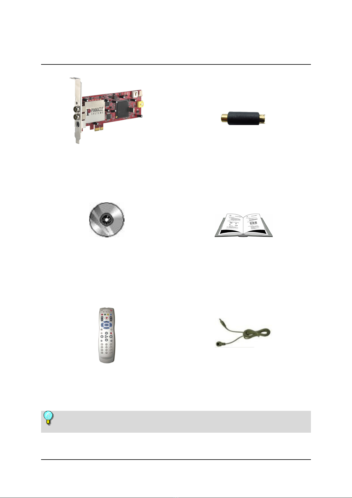
Congratulations on becoming the proud owner of a PCTV 3010iX!
PCTV 3010iX is a PCI Express dual hybrid tuner card. It allows you to receive
digital terrestrial TV (DVB-T), analog TV and FM radio. Depending on the
antenna signals connected and the software you are using, you can freely choose
the two channels to be received/recorded at the same time:
2 DVB-T channels (TV or radio) or
1 analog channel (TV or radio) plus 1 DVB-T channel (TV or radio) or
2 analog channels (TV or radio).
Plus, you can use the analog video input, for example, to digitize your old video
cassettes.
DVB-T (Digital Video Broadcasting Terrestrial), digital terrestrial TV, offers a
wide selection of channels with excellent image and sound quality, without the
need of a satellite dish or a cable connection.
Additional services planned for the future include digital radio, interactive TV,
and IP data reception. Some of these services are already available in selected
areas. More information about DVB-T can be found on the Internet, for
example, at HUwww.dvb.orgUH.
And now have fun with your PCTV 3010iX!

2
Package Contents
PCTV 3010iX card
(illustration is a sample)
Video adapter
Installation CD PDF files on CD-ROM: User Manual,
hardware operating instructions,
remote control operating instructions
Remote control with batteries and receiver cable
(illustrations are samples)
Depending on the version of your product, package contents may vary.

3
Recommended System Requirements
Your system must satisfy the following requirements in order for your
PCTV 3010iX to function smoothly:
Bus System
PCI Express Rev. 3.0
Processor
Pentium D with 3.0 GHz or equivalent AMD Athlon 4800
Working memory
512 MB RAM
Hard disk
U-DMA hard disk with 20 GB free disk space
Graphics card
DirectX 9-compatible graphics card
Sound card
DirectX 9-compatible sound card
CD-/DVD burner
Operating system
Windows XP (Home Edition, Professional Edition or Media Center Edition
2005) with the latest Service Pack

4
For Your Own Safety
If you purchased your PCTV 3010iX together with a PC and it is already
installed, skip the next few chapters and continue with the chapter "Connecting
the Equipment".
In the interest of your own safety and the flawless functioning of your new
PCTV 3010iX and computer system, note the following:
Computer components are sensitive to static charge. Divert any electrostatic
charge from your body before touching the components with your hands or
any tools.
Before opening the computer, make sure that the power plug is disconnected
from the wall outlet.

5
Hardware Installation
Preparing Installation
The only tool you need for the installation is a screwdriver.
Divert any possible electrostatic charge from your body by touching the
casing of your PC.
Turn off your computer and all peripheral devices. Disconnect the computer
from the power supply and all necessary components.
Loosen the computer cover screws and remove the cover.
Select a free PCI Express slot. Remove the slot cover at the back of the
computer. Make sure to keep the screws in a safe place.
C

6
Using PCTV 3010iX Hardware
Insert the card into the PCI Express slot. To do so, hold the card at the top
and push it down into the slot while applying even pressure at both ends.
Press down on the upper edge so that the card fits firmly in the slot.
If you cannot easily insert the card into the slot, do not use force since this
may bend the contact springs on the socket connector. Instead, remove the
card and try to insert it again.
After Installation
After you have inserted the hardware, tighten the card retaining bracket
firmly on the back of the computer.
Now place the cover onto your computer and connect the peripheral devices.

7
Connecting the Equipment
C
Remote control
receiver
(optional)
Antenna input 2
or
cable terminal
(optional)
For example:
camcorder, video recorder,
CCD camera, DVD/VCD player,
video game console
Composite Video or
S-Video input
(via adapter)
(optional)
Antenna input 1
or
cable terminal
Audio output to sound card
(internal, optional)
Composite Video or
S-Video input
(internal, optional)
Audio input
(internal, optional)
For auto-wake up
(internal, optional)
to motherboard
from PC power switch
(switchable
antenna power supply)
C

8
Tips on Positioning the Antenna
Take note of the following in order to achieve the best possible digital television
reception:
Wherever possible, place the antenna in the direction of the nearest
transmitter.
If you use an indoor antenna, position it near a window, if possible.
Try to position any indoor antenna as high as possible (for example, on top of
a cupboard).
An indoor antenna should not be located near a computer monitor, television
or the like.
Make certain to have the proper polarization if you use an active flat antenna
(if you are not certain, you can find out whether the antenna should have a
transverse or upright position by trial and error).
For active antennas without a separate power supply, please use the Antenna
input 1 and activate the antenna power supply.
Only double-shielded antenna cable should be used.

9
Technical Data
Bus System
PCI Express Rev. 3.0
Video Decoder / Analog Demodulator /
PCI Express Controller
Philips SAA7162
TV Tuner
2 x Philips TDA 8275A
The frequency range is 45,75 to 863,25 MHz.
DVB-T Demodulator
2 x Philips TDA 10046A
16,64 QAM, QPSK
6,7,8 MHz bandwidth
UHF, VHF
Supported Formats
DVB-T
PAL / SECAM / NTSC
FM Radio
Antenna Input Terminals
Two 75 Ohm IEC
Both antenna input terminals are randomly usable
The Antenna Input 1 provides power for DVB-T antenna

10
Video Input Terminals
Mini-DIN 7-pole for S-Video or Composite Video (Cinch via adapter)
Internal Connector
Audio Connectors
Internal audio output terminal (to the sound card) via a 4-pole connector
Internal audio input terminal via a 4-pole connector
Additional Connectors
IR remote connector to attach optional IR receiver cable
Wake-Up connector
Sensitivity
DVB-T: minimum -86 dBm
Analog: minimum 30 dBµ
Analog Quality
Minimum SN 41 dB @ 60 dBµ

11
Konformitätserklärung nach ISO/IEC Guide 22
Declaration of conformity in accordance with
ISO/IEC Guide 22
Nr. / No 1.00
Anbieter / Supplier : Pinnacle Systems GmbH
Anschrift / Address : Frankfurter Strasse 3c
38122 Braunschweig, Germany
Produkt / Product : PCTV 3010iX
Das oben beschriebene Produkt ist konform mit: / The product described above is in conformity with:
Dokument-Nr.
Document No.
Titel
Title
EN 55013 : 2002
Funkstöreigenschaften von Rundfunkempfängern und verwandten Geräten der Unterhaltungselektronik
Limits and methods of measurement of radio disturbance characteristics of broadcast receivers and associated
equipment
EN 55020 : 2003 Störfestigkeit von Rundfunkempfängern und verwandten Geräten der Unterhaltungselektronik
Electromagnetic immunity of broadcast receivers and associated equipment
EN 61000-4-2 : 2001
Störfestigkeit gegen Entladung statischer Elektrizität
Electrostatic discharge immunity test
EN 61000-4-3 : 2001
Störfestigkeit gegen hochfrequente elektromagnetische Felder
Radiated, radio-frequency, electromagnetic field immunity test
EN 61000-4-4 : 2002 Störfestigkeit gegen schnelle transiente elektrische Störgrößen/BURST
Electrical fast transient/burst immunity test
EN 61000-4-5 : 2001 Störfestigkeit gegen Stoßspannungen/SURGE
Surge immunity test
EN 61000-4-6 : 2001 Störfestigkeit gegen leitungsgeführte Störgrößen, induziert durch hochfrequente Felder
Immunity to conducted disturbances, induced by radio-frequency fields
EN 61000-4-8 : 2001 Störfestigkeit gegen Magnetfelder mit energietechnischen Frequenzen
Power frequency magnetic field immunity test
EN 61000-4-11 : 2001 Störfestigkeit gegen Spannungseinbrüche, Kurzzeitunterbrechungen und Spannungsschwankungen
Voltage dips, short interruptions and voltage variations immunity tests
EN 61000-3-2 : 2001
Grenzwerte für Oberschwingungsströme
Limitations for harmonic currents
EN 61000-3-3 : 2002 Grenzwerte für Spannungsschwankungen und Flicker
Limitations of voltage fluctuations and flicker
EN 60950 : 2001 Sicherheit von Einrichtungen der Informationstechnik
Safety of information technology equipment
Dieser Erklärung liegt zugrunde: Prüfbericht(e) des EMV-Prüflabors
This certification is based on: Test report(s) generated by EMI-test laboratory
Braunschweig, 26. Oktober 2005 / October 26th, 2005
......................................... .................................................
Dr. Alexander Roy Jörg Tewes
Director Hardware Engineering Director Engineering
(Rechtsverbindliche Unterschrift / Legally Binding)

12
Notes
Table of contents