manuals.online logo
Brands
  1. Home
  2. •
  3. Brands
  4. •
  5. Pioneer
  6. •
  7. Amplifier
  8. •
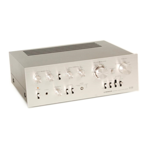
  9. Pioneer A-7 User manual

Pioneer A-7 User manual

Other Pioneer Amplifier manuals

Pioneer A-757 User manual

Pioneer

Pioneer A-757 User manual

Pioneer A-40AE User manual

Pioneer

Pioneer A-40AE User manual

Pioneer A-P710 User manual

Pioneer

Pioneer A-P710 User manual

Pioneer GM-520T/XU/UC User manual

Pioneer

Pioneer GM-520T/XU/UC User manual

Pioneer GM-X952 User manual

Pioneer

Pioneer GM-X952 User manual

Pioneer A-60 User manual

Pioneer

Pioneer A-60 User manual

Pioneer SA-708 User manual

Pioneer

Pioneer SA-708 User manual

Pioneer PRS-D3000SPL/X1H/EW User manual

Pioneer

Pioneer PRS-D3000SPL/X1H/EW User manual

Pioneer GM-X422 User manual

Pioneer

Pioneer GM-X422 User manual

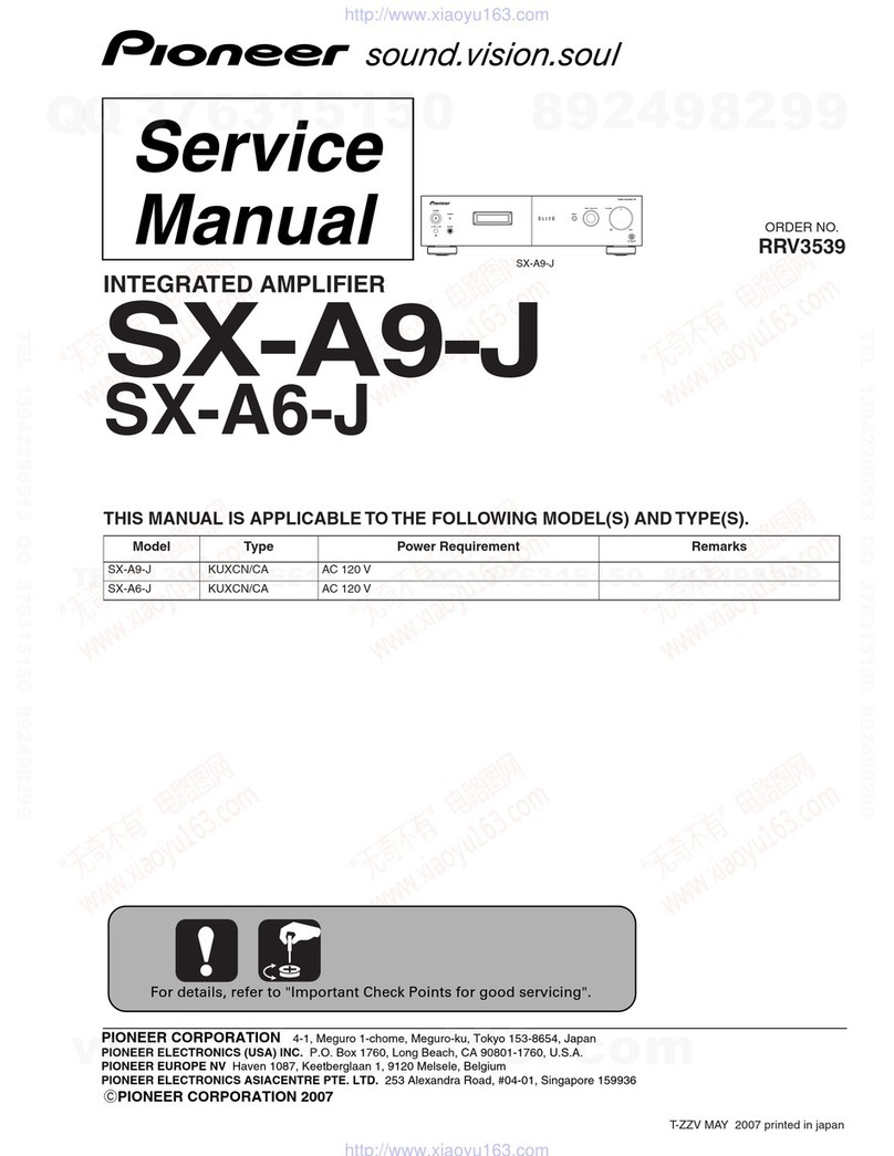
Pioneer Elite SX-A9-J User manual

Pioneer

Pioneer Elite SX-A9-J User manual

Pioneer GM-D510M/X1R/EW User manual

Pioneer

Pioneer GM-D510M/X1R/EW User manual

Pioneer AVM-P7000R User manual

Pioneer

Pioneer AVM-P7000R User manual

Pioneer GM-ME300X1C User manual

Pioneer

Pioneer GM-ME300X1C User manual

Pioneer PRS-D3000SPL User manual

Pioneer

Pioneer PRS-D3000SPL User manual

Pioneer M-F10 User manual

Pioneer

Pioneer M-F10 User manual

Pioneer A-443 User manual

Pioneer

Pioneer A-443 User manual

Pioneer VSA-AX10Ai User manual

Pioneer

Pioneer VSA-AX10Ai User manual

Pioneer VSA-AX10Ai-S User manual

Pioneer

Pioneer VSA-AX10Ai-S User manual

Pioneer A-443 User manual

Pioneer

Pioneer A-443 User manual

Pioneer M-EV51 User manual

Pioneer

Pioneer M-EV51 User manual

Pioneer SA-1040 User manual

Pioneer

Pioneer SA-1040 User manual

Pioneer SM-700 Setup guide

Pioneer

Pioneer SM-700 Setup guide

Pioneer GM-D1004 User manual

Pioneer

Pioneer GM-D1004 User manual

Pioneer A-51 User manual

Pioneer

Pioneer A-51 User manual

Popular Amplifier manuals by other brands

Magnat Audio EDITION FOUR Owner's manual/warranty document

Magnat Audio

Magnat Audio EDITION FOUR Owner's manual/warranty document

Inter-m PA-2000A Operation manual

Inter-m

Inter-m PA-2000A Operation manual

Yamaha TX6n owner's manual

Yamaha

Yamaha TX6n owner's manual

Peavey TNT 150 user guide

Peavey

Peavey TNT 150 user guide

Bosch LBB 1903/10 Installation and user instructions

Bosch

Bosch LBB 1903/10 Installation and user instructions

Avocent Emerge DA1200D Installer/user guide

Avocent

Avocent Emerge DA1200D Installer/user guide

Redgum RGi35 operating instructions

Redgum

Redgum RGi35 operating instructions

Cambridge Audio AXA25 user manual

Cambridge Audio

Cambridge Audio AXA25 user manual

Alpine MRP-M200 owner's manual

Alpine

Alpine MRP-M200 owner's manual

Technical Pro H1502UrBT user manual

Technical Pro

Technical Pro H1502UrBT user manual

FMS EMGZ307 operating manual

FMS

FMS EMGZ307 operating manual

Racal Instruments 5601 user manual

Racal Instruments

Racal Instruments 5601 user manual

Valcom V-1094A Technical specifications

Valcom

Valcom V-1094A Technical specifications

Cambridge Audio 851D user manual

Cambridge Audio

Cambridge Audio 851D user manual

QSC 3800 Specifications

QSC

QSC 3800 Specifications

NAD C300 owner's manual

NAD

NAD C300 owner's manual

Rotel RMB-1077 owner's manual

Rotel

Rotel RMB-1077 owner's manual

Peavey Monitor 300 Series operating guide

Peavey

Peavey Monitor 300 Series operating guide

manuals.online logo
manuals.online logoBrands
  • About & Mission
  • Contact us
  • Privacy Policy
  • Terms and Conditions

Copyright 2025 Manuals.Online. All Rights Reserved.

ORDER
NO.
ART-597-0
NON
SWITCHING
AMP
STEREO
AMPLIFIER
A-7
MODEL
A-7
COMES
IN
SIX
VERSIONS
DISTINGUISHED
AS
FOLLOWS:
Type
Voltage
Remarks
|
HE
220V
and
240V
(Switchable)
Europe
model
aaa
3
HB
220V
and
240V
(Switchable)
U.K.
model
|
KU
120V
only
U.S.A.
modei
=.
=
120V
only
Canada
model
110V,
120V,
220V
and
240V
(Switchable)
U.S.
military
modet
S
110V,
120V,
220V
and
240V
(Switchable)
General
export
model
|
This
service
manual
is
applicable
to
the
HE
and
HB
types.
When
repairing
the
KU,
KC,
S/G
and
S
types,
please
see
the
additional
service
manual.
Ce
manuel
d’instruction
se
refére
au
mode
de
réglage,
en
frangais.
Este
manual
de
servicio
trata
del
método
de
ajuste
escrito
en
espanol.
CONTENTS
1<,
SPECIFICATIONS
24.¢
sn
ins
ad
sensi
wedsn
2
8.
ELECTRICAL
PARTS
LIST............---
oe
2.
FRONTPANEL
FACILITIES..............
3
9.
SCHEMATIC
DIAGRAM..............0..
25
S..
iPARTS
LOCATION,
és.
So
canatpaeneeadeyers
6
10;
PACKING’
s.cciqg
an
cuniarny
are
aaa
ae
32
4.
CIRCUIT
DESCRIPTIONS................
8
11;
ADJUSTMENTS
¢
05
edulis
Uae
ed
eerie
as
33
5.
BLOCK
DIAGRAM............-5+++-555
9
REGEAGE
a3
anor
eacsltee
y
base
ad
inten
etned
34
6.
EXPLODED
VIEWS
..............--000-5
1
PIUSTES
coho
vic
above
Goma
hteautecdlvean®,
x2
35
7.
P.C.
BOARDS
CONNECTION
DIAGRAM......
17
PIONEER
ELECTRONIC
CORPORATION
4-1,
Meguro
1-Chome,
Meguro-ku.
Tokyo
153,
Japan
U.S.
PIONEER
ELECTRONICS
CORPORATION
&5
Oxford
Drive.
Moonachie,
New
Jersey
07074,
USA.
PIONEER
ELECTRONIC
(EUROPE)
N.V.
Luithagen-Haven
S,
2030
Antwerp,
Belgium
PIONEER
ELECTRONICS
AUSTRALIA
PTY.
LTD.
178-184
Boundary
Road,
Braeside,
Victoria
3195,
Australia
YU
©
DEC.
1980
Printed
in
Japan
1.
SPECIFICATIONS
Amplifier
Section
Continuous
Power
Output
is
70
watts*
per
channel,
min.
at
8
ohms
from
20
Hertz
to
20,000
Hertz
with
no
more
than
0.007%
total
harmonic
distortion.
Continuous
Power
Output
at
1
kHz
(both
channels
driven)
T.H.D.
0.007%,
Bohms
..............08
78
watts
per
channel
Total
Harmonic
Distortion
(20
Hertz
to
20,000
Hertz,
8
ohms,
from
TUNER)
continuous
rated
power
output
.......
No
more
than
0.007%
35
watts
per
channel
power
output
..
No
more
than
0.005%
Intermodulation
Distortion
(50
Hertz:7,000
Hertz
=
4:1,
8
ohms,
from
TUNER)
continuous
rated
power
output
.......
No
more
than
0.005%
35
watts
per
channel
power
output
..
No
more
than
0.003%
Damping
Factor
(20
Hertz
to
20,000
Hertz,
8
ohms)
cds
shea
heat
crowdba
beleuee
vic
hontes
nes
abies
Pe
GONG
Ga
Rooke
aR
Aeeeee
60
Input
Sensitivity/Impedance
PHONO
MM
........c2cccesceeeceeetereeeeeees
2.5
mV/50
kilohms
PHONO
MC
1...
2.
cee
cceeeenecee
este seen
eens
0.25
mV/100
ohms
TUNER,
AUX,
TAPE
PLAY
1,
2
..........
150
mV/50
kilohms
Phono
Overload
Level
(T.H.D.
0.0015%,
1,000
Hz)
PHONO:MM
icc
ciiesecccsdeesesceetssscsecdssescacsenssessves
200
mV
PHONO'MG:
ccoveceschisendemesssscsvetatacessrsvsniedeeneneres
20
mV
Output
Level
TAPE
REC
12s
te
csssscitiessewudeces
Pavececs
150
mV
Speaker:
is.
cccccsiccevisvetseccbenedes
A/OFF,
B/OFF
(6~16
2)
Frequency
Response
PHONO
MM
(RIAA
Equalization)
Racudileodudtedes
tua
chewtavenchworuas
sate
20
Hz
to
20,000
Hz+0.3
dB
TUNER,
AUX,
TAPE
PLAY
1,
2.....
5
Hz
to
100,000
Hz*$
dB
Tone
Control
BASS
ees
ieecintaiied
cc
dennbaeneconsenehenetenes
tes
+10
dB
(100
Hz)
TREBLE
visdt
sccetvsecaveteetactetcertertenenseueeens
+10
dB
(10
kHz)
Filter
LOW
(SUBSONIC)
........ccceceeeee
eee
eee
es
20
Hz
(6
dB/oct.)
Loudness
Contour
{Volume
control
set
at
—40
dB)
iikiweStion
cee
add
ola
eaew
needed
cee
+9
dB
(100
Hz),
+3
dB
(10
kHz}
Hum
and
Noise
(IHF,
short
circuited
A
network)
PHONO.
MM)
icecczcicetcccstiec
eat
ees
sn.
tea
onde
deegsenane
88
dB
PHONO
MC
oeciceciccescsseceae
ad
obaecsnacssttassactaber
doses
70
dB
TUNER,
AUX,
TAPE
PLAY
1,
2
.......ecceceeeeceee
eee ees
110
dB
Hum
and
Noise
(DIN,
continuous
rated
power
output/50
mW)
PHONO
MM
........cccececscncec
ee
etecenteneneeeneeees
80
dB/66
dB
PHONO!
MGo
tos
vecasecatasegneoedt
atepetotecds
even?
70
dB/65
dB
TUNER,
AUX,
TAPE
PLAY
1,
2...............0085
95
dB/69
dB
Mini
sees
dedeszsea
teceenueseessteueaeset
vee
ccisebspniedenvevesicdons
—20
dB
Miscellaneous
Power
Requirements
HE,
HB
model
..............
220/240
V
(switchable),
50/60
Hz
Power
Consumption
HE,
HB
models
..............cccccecsesececeeeecsenes
420
W
(max.)
Dimensions
...........0.cseseeeeee
420
(W)
x
132
(H)
x
423
(D)
mm
16-9/16
(W)
x
5-3/16
(H)
x
16-11/16
(D)
in
Weight
(without
package)
................66-
12.2
kg
(26
Ib
14
oz)
Furnished
Parts
Operating
Instructions
............0cceeeeeu
eee
1
(HE
mode!
only;
2)
*Measured
pursuant
to
the
Federal
Trade
Commission’s
Trade
Regulation
rule
on
Power
Output
Claims
for
Amplifiers.
NOTE:
Specifications
and
the
design
subject
to
possible
mofifications
without
notice
due
to
improvements.
2.FRONT
PANEL
FACILITIES
.
NON
SWITCHING
ANE
W
PIONEER
sTEREO
ameUFIER
4-7
()
POWER
SWITCH
Power
is
supplied
to
the
stereo
amplifier
as
soon
as
this
switch
is
depressed
to
the
ON
position.
The
power
is
turned
off
when
the
switch
is
released
to
the
OFF
position.
As
soon
as
the
power
switch
has
been
set
to
ON,
the
muting
circuit
is
actuated,
the
PROTECTION-RED
indicator
lights
up
red/and
after
about
6
seconds
when
the
muting
circuit
is
released,
the
indicator
goes
from
red
to
green.
(2)
TREBLE
CONTROL
This
is
used
to
adjust
the
treble
(high-frequency
range)
sound.
Rotate
this
control
with
the
LINE
STRAIGHT-OFF
switch
set
to
the
depressed
position.
The
treble
is
emphasiz-
ed
when
the
control
is
rotated
clockwise
from
its
center
posi-
tion
and
attenuated
when
it
is
rotated
counterclockwise.
3)
BASS
CONTROL
This
is
used
to
adjust
the
bass
(low-frequency
range)
sound.
Rotate
this
control
with
the
LINE
STRAIGHT-OFF
switch
set
to
the
depressed
position.
The
bass
is
emphasized
when
the
control
is
rotated
clockwise
from
its
center
position
and
at-
tenuated
when
it
is
rotated
counterclockwise.
(4)
FUNCTION
SWITCHES
These
are
used
to
select
the
sound
source.
At
the
left
of
each
switch
is
a
symbol
function
indicator
which
lights
when
the
corresponding
switch
has
been
depressed.
This
indicates
that
the
lighted
function
has
been
selected.
PHONO:
Depress
for
playing
records
on
a
turntable
con-
nected
to
the
PHONO
jacks.
TUNER:
Depress
for
listening
to
a
program
on
a
tuner
connected
to
the
TUNER
jacks.
AUX:
Depress
for
listening
to
the
sound
from
a
stereo
component
connected
to
the
AUX
jacks.
TAPE
1:
Depress
to
listen
to
a
tape
in
a
tape
deck
con-
nected
to
the
TAPE
1
jacks
or
to
monitor
a
recording.
TAPE
2:
Depress
to
listen
to
a
tape
in
a
tape
deck
con-
nected
to
the
TAPE
2
jacks
or
to
monitor
a
recording.
NOTE:
Depress
only
one
FUNCTION
switch
at
a
time.
The
desired
pro-
gram
source
may
not
be
selected
if
two
or
more
switches
are
depressed
at
the
same
time.
©)
VOLUME
CONTROL
This
is
used
to
adjust
the
volume
of
sound
heard
through
the
speakers
or
headphones.
No
sound
is
heard
when
it
is
set
to
the
‘‘0’
position.
To
increase
the
volume,
rotate
this
control
slowly
clockwise
(().
©)
MUTING
-20
dB
SWITCH
The
volume
is
attenuated
by
—20
dB
when
this
switch
is
depressed
to
the
ON
position
(MUTING
indicator
lights).
The
switch
can
be
used
effectively
when
the
stylus
descends
on-
to
the
record
during
record
play,
when
the
sound
is
to
be
turned
down
temporarily
and
when
you
want
to
adjust
the
sound
precisely
as
you
listen
to
a
program
source
under
low
sound
level
conditions.
@
PHONES
JACK
Connect
the
plug
on
your
headphones
to
this
jack
when
listening
to
a
program
in
private.
To
listen
to
a
program
through
the
headphones,
release
both
the
SPEAKERS
A
and
B
switches.
©
REC
OUT
SELECTOR
SWITCH
This
is
used
to
select
the
output
signal
which
is
fed
out
to
the
TAPE
REC
jacks.
COPY
2
>
1:
COPY
1
>
2:
SOURCE:
PHONO:
TUNER:
AUX:
The
output
signal
is
fed
out
from
the
TAPE
2
PLAY
jacks
to
the
TAPE
1
REC
jacks
(when
dubbing
a
tape
from
TAPE
2
to
TAPE
1).
The
output
signal
is
fed
out
from
the
TAPE
1
PLAY
jacks
to
the
TAPE
2
REC
jacks
(when
dubbing
a
tape
from
TAPE
1
to
TAPE
2).
The
output
signal
of
the
program
source
(PHONO,
TUNER,
AUX,
etc.)
selected
by
the
FUNCTION
switch
is
fed
out
to
the
TAPE
1
REC
and
TAPE
2
REC
jacks.
The
output
signal
from
the
PHONO
jacks
is
fed
out
to
the
TAPE
1
REC
and
TAPE
2
REC
jacks.
The
output
signal
from
the
TUNER
jacks
is
fed
out
to
the
TAPE
1
REC
and
TAPE
2
REC
jacks.
The
output
signal
from
the
AUX
jacks
is
fed
out
to
the
TAPE
1
REC
and
TAPE
2
REC
jacks.
@
MODE
SELECTOR
This
is
used
to
select
the
mode.
m
STEREO:
Set
here
for
ordinary
stereo
listening.
mMONO:
Set
here
to
mix
the
left
and
right
channel
stereo
input
signals
and
hear
them
in
mono
through
both
the
left
and
right
speakers.
LINE
STRAIGHT-OFF
SWITCH
When
this
switch
is
released
to
the
ON
position
(the
LIME
STRAIGHT
indicator
lights),
the
signal
from
the
input
jacks
is
directly
sent
to
the
power
amplifier
input
without
passing
through
the
tone
control
circuit.
When
this
switch
is
depressed
to
the
OFF
position,
the
input
signal's
tone
quality
can
be
adjusted
with
the
tone
controls.
()
PHONO
MM/MC
SELECTOR
SWITCH
Set
this
switch
to
the
position
corresponding
to
the
cartridge
used
when
playing
records
on
a
turntable
connected
to
tre
PHONO
jacks.
MM:
Set
here
when
using
an
MM
cartridge.
MC:
Set
here
when
using
an
MC
cartridge.
42
SPEAKERS
A/B
INDICATORS
These
light
when
one
of
the
SPEAKERS
switches
has
been
depressed.
(3)
MODE
INDICATOR
BALANCE
INDICATOR
(3
LINE
STRAIGHT
INDICATOR
This
lights
when
the
LINE
STRAIGHT-OFF
switch
has
been
released
to
ON
in
place
of
the
BALANCE,
MODE
and
TONE
indicators.
TONE
INDICATOR
This
lights
when
the
tone
control
circuitry
has
been
ac-
tuated,
(2
LOUDNESS
INDICATOR
This
lights
when
the
LOUDNESS
siwtch
has
been
set
to
ON.
SUBSONIC
FILTER
INDICATOR
This
lights
when
the
SUBSONIC
FILTER
switch
has
been
set
to
ON.
(3
BALANCE
CONTROL
This
is
used
to
adjust
the
balance
of
the
sound
from
the
left
and
right
channels.
When
rotated
clockwise
from
its
center
position,
the
volume
of
the
left
(L)
channel
is
reduced;
when
rotated
counterclockwise,
the
volume
of
the
right
(R)
chan-
nel
is
reduced.
To
adjust
the
balance,
first
set
the
BALANCE
control
to
its
center
position,
set
the
MODE
selector
to
MONO
and
rotate
the
control
so
that
the
sound
seems
to
be
coming
from
the
midpoint
between
the
left
and
right
speakers.
@0)
SPEAKERS
SWITCHES
These
are
used
to
select
the
speakers
through
which
you
will
listen
to
the
sound.
When
one
of
the
switches
is
depressed,
the
corresponding
speaker
indicator
will
light
to
indicate
that
the
selected
speakers
are
now
working.
A:
The
sound
is
heard
from
the
speakers
connected
to
the
speaker
A
terminals.
B:
The
sound
is
heard
from
the
speakers
connected
to
the
speaker
B
terminals.
No
sound
will
be
heard
when
SPEAKERS
A
and
B
switches
are
both
released.
This
is
the
position
at
which
the
sound
can
be
heard
through
the
headphones.
@)
SUBSONIC
FILTER
SWITCH
The
subsonic
filter
with
the
15
Hz
cutoff
frequency
is
ac-
tuated
when
this
switch
is
depressed
to
the
ON
position
(the
SUBSONIC
FILTER
indicator
lights).
a
This
filter
serves
to
attenuate
frequencies
lower
than,
20
Hz
with
a
6
dB/oct
slope
and,
therefore,
it
can
be
used
to
sup-
press
the
ultra-low-range
noise
which
is
generated
by
record
warp
and
other
factors.
This
noise
cannot
actually
be
heard
by
the
ear
but
it
can
cause
cross
modulation
distortion
and
even
speaker
damage.
Use
this
switch
when
required
during
record
play.
Q2)
LOUDNESS
SWITCH
The
bass
and
treble
sound
is
emphasized
when
this
switch
is
depressed
to
the
ON
position
(LOUDNESS
indicator
lights)
under
low
volume
listening
conditions.
When
the
volume
of
sound
is
low,
the
capability
of
the
ear
to
pick
up
the
bass
and
treble
sound
drops
off,
compared
with
high
volume
listening
conditions.
The
LOUDNESS
switch
compensates
for
this
characteristic
of
the
ear.
The
bass
and
treble
are
emphasized
when
the
switch
is
set
to
ON
and
the
sound
comes
alive
even
when
the
volume
is
low.
@)
REC
OUT
1,
2
INDICATORS
These
indicate
the
tape
deck
which
is
recording
in
accor-
dance
with
the
position
selected
by
the
REC
OUT
SELEC-
TOR
switch.
@)
PROTECTION-RED
INDICATOR
This
lights
in
red
or
green,
depending
on
the
operating
mode
of
the
power
protection
circuit.
@5)
REC
SELECTOR
INDICATOR
This
indicates
the
program
source
(PHONO,
TUNER,
AUX,
etc.)
being
recorded
in
accordance
with
the
position
of
the
REC
OUT
SELECTOR
switch.
@6)
MUTING
INDICATOR
This
lights
in
accordance
with
the
position
of
the
MUTING
switch.
@)
OUTPUT
POWER
8
2
METER
This
indicates
the
output
level
when
speakers
with
an
8-ohm
impedance
are
connected
to
the
speaker
terminals.
L
is
for
the
left
channel
and
R
for
the
right
channel.
FUNCTION
INDICATORS
The
indicator
corresponding
to
the
selected
FUNCTION
switch
lights.
3.
PARTS
LOCATION
NOTES:
e
Parts
without
part
number
cannot
be
supplied.
e
The
A
mark
found
on
some
component
parts
indicates
the
importance
of
the
safety
factor
of
the
part.
Therefore,
when
replacing,
be
sure
to
use
parts
of
identical
designation.
e
For
your
Parts
Stock
Control,
the
fast
moving
items
are
indicated
with
the
marks
xx
and
*.
xk
GENERALLY
MOVES
FASTER
THAN
x.
This
classification
shall
be
adjusted
by
each
distributor
because
it
depends
on
model
Front
Panel
View
number,
temperature,
humidity,
etc.
Push
knob
(C)
:
AAD-340
Function
knob
(A)
AAD-341
eee
]
Function
knob
(B)
AAD-342
Knob
(B)
AAB-259
Function
knob
(C)
AAD-343
Push
knob
(A)
AAD-338
OT
Knot
(A)
Front
panel
assembly
AAB-258
ANB-980
Door
assembly
Function
knob
(D)
ANB-975
AAD-344
Push
knob
(C)
Function
knots
(E)
AAD-340
AAD-345
Center
plate
ANR-331
ANN-333
Front
View
with
Front
Panel
Removed
*
Variable
(TREBLE)
ACT-144
%
&
Rotary
switch
ASK-154
Variable
(VOLU
ME)
ACT-706
{
!
%
Variable
(BASS)
_F
ACT-144
Phares
jack
AKN-O
229
A\
&*
Push
switch
(POWER)
ASG-535
*
Variable
(BALANCE)
yr
Power
adiccator
ACV-143
AAV-3(1
Top
View
Power
supply
assembly
Switch
assembly
GWR138
AWS-154
EQassembly
AWF-048
J\
%&
Power
transformer
Z
ATT-770
Capacitor
assembly
220V/240V
GWR-131
Power
amplifier
assembly
AWH-104
Tone
control
assembly
GWG-152
Function
switch
assembly
GWN-185
Bottom
View
Switch
assembly
Function
switch
assembly
GWM-185
Power
amplifier
issembly
AWH-104
Capacitor
assembly
GWR-131
EQ
issembiy
AW!-048
Switch
issembly
AWS-1%4
A-7
Rear
Panel
View
Pin
jack
6P
AKB-079
Pin
jack
4P
AKB-078
Terminal
(SPEAKER}
AKE-055
4.
CIRCUIT
DESCRIPTIONS
The
circuitry
of
the
A-7
is
basically
the
same
as
that
of
model
A-8
with
the
exception
of
following
sections.
For
details
of
circuit
description,
please
see
the
circuit
description
of
the
model
A-8.
1.
The
A-7
equalizer
amp
can
not
be
switched
between
MM
R
LOAD
and
MC
C
LOAD.
2.
The
power
amplifier
ass’y
differs
from
the
drive
circuit
A-8
at
the
final
stage.
Bonnet
case
ANE-330
rN
.
2\%*
Line
voltage
selector
AKX-057
“\
Strain
relief
AEC-327
/\,
AC
power
cord
ADG-051
(HB)
ADG-041
(HE)
Mark
Part
No.
Symbol
&
Description
CCDSL
680J
50
CKDYB
472K
50
CKDYB
471K
500
CKDYF
1032
50
CQMA
102K
250
RESISTORS
C41,
C42
C57,
C58
C53,
C54
C35, C36, C45,
C46
C37,
C38
Note:
When
ordering
resistors,
convert
the
resistance
value
into
code
form,
and
then
rewrile
the
part
no.
as
before.
Mark
Part
No.
Symbol
&
Description
*&
ACP-019
A
RO“%PMFOOO
J
Vso
we
RD%PMFOOO
J
RD%PMOOO
JNL
A
RD%PSF
2215
RD%PSOOO
J
RD%PMOOO
J
SEMICONDUCTORS
Mark
Part
No.
kk&
2SK129A
kk
2802291
&&
=2SA979
ke
=25C2259
*&*&
2SA733A
(2SA1015)
(2SA1115)
(2SA992)
kk
2SA905A
ww
2SC1I91I5A
(2SC1915)
*#*&
=
2SC2603
(2SC1400)
wkk&
2SA1115
(2SA750)
kk
2SA893A
*&*&
=
2SC1890A
*&*&
=
28C2275
kk
2SA985
*&%*&
=2SB507P
(2SB834)
(2SB682)
&%&
=2SD313P
(2SD880)
(2SD712)
wk*e
NJM4558DX
(uPC4558C)
%&
181555
(US1035)
(1$2076)
(1$2473)
*&
=
MZ-047
%&
MZ-150
(W2Z-150)
VR1,VR2_
Semi-fixed
1002
(B)
R31,
R32,
R39,
R40,
R61,
R62,
R91,
R92,
R121, R122,
R41,
R42
R35—R40,
R43, R44,
R63,
R64,
R69—R72,
R91—RYIGB,
R113,
R114
R3,
R4,
R9Q—R12
R111,
R112
R73—R76
R1,
R2,
R5,
R6,
R15—R26,
R29,
R30,
R33,
R34,
R45—R60,
R65—
R68,
R77—R84,
R89,
R90,
R95—
R98,
R107—R110,
R115—R120
Symbol
&
Description
Qi,
Q2
Q3,
Q4
Q5,
O6
Qg,
Q10
Q11,Q12
Q13,
Q14
Q15,
Q16
Q17,
Q18, Q23,
Q24
Qi9—Q22
Q25,
026
Q27,
Q28
Q29,
Q30
Q31,
Q32
Q101
Q102
Q33
D1—D4,
D7, 08,
D13—D20,
D25—
D28,
D39-—D42
021-—D24
D33,
D34
Mark
Part
No.
Symbol
&
Description
*
MZL240
*
=STV2H-O
OTHERS
Mark
Part
No.
TH102-2
TH103-2
D101,
D102
D11,D12
Symbol
&
Description
TH1,
TH2
TH3,
TH4
SWITCH
ASSEMBLY
(AWS-159)
RESISTORS
Note:
When
ordering
resistors,
convert
the
resistance
value
into
code
form,
and
then
rewrite
the
part
no.
sa
before.
Mark
_
Part
No.
Symbol
&
Description
RD%PM
OOO
J
R1-R11
SWITCH:
CAPACITOR-OTHER
Mark
Part
No.
xk*
ASX-156
ACE-075
CKDYB
391K
50
AKB-078
Symbol
&
Description
$1
Side
switch
C1
C2—C5
Pin
jack
4P
PROTECTION
ASSEMBLY
(GWM-236)
CAPACITORS
Mark
Part
No.
CQMA
473K
50
CEA
R47M
50L
CEA
471M
6L
CEA
101M
16L
CEA
2R2M
100L
RESISTORS
Symbol
&
Description
C201,
C202
C203,
C204
C205
C206
C207
Note:
When
ordering
resistors,
convert
the
resistance
value
into
code
form,
and
then
rewrite
the
part
no.
as
before.
Mark
Part
No.
RS1P100J
RS2PL100J
RS1P391J
RO%PM
OO
J
SEMICONDUCTORS
Mark
Part
No.
Symbol
&
Description
R201,
R202
R203,
R204
R215
R205—R214
Symbol
&
Description
*&*
=2SC1890A
**
=2SC945A
*&*
2SA733A
*&*
=
2SC1384
*
182471
*
182473
(1S1555)
(1$2076)
*
=MZ-150
(WZ-150)
OTHER
Mark
Part
No.
kk
ASR-068
Q201,
Q202
Q203,
Q204
Q205
Q206
D201—D204
D205
D206
Symbol
&
Description
Relay
RL4
4.P.C.
BOARD
PATTERN
4.1
EQ
ASSEMBLY
(AWF-054)
Qinas
Qs a6
Q7
Qs6
Qa
~ai2
O1~6,9~14
182473
07.8
MZL320
Qis~
Qe
|
wv
Ahn
4
4.2
POWER
AMPLIFIER
ASSEMBLY
(AWH-117)
4.4
PROTECTION
ASSEMBLY
(GWM-236)
aze
Q30
Q24
G20
aze
ato2z
927
23
Q26
3
Q205
Q204
Q201Q202
a6
Qioas
azz
arz
Q4
Qa
a2
Qe
a2
aio
gar
azo
ais ais
ai
aisas
ait
Q21.ai7
a9 as
Q33
Q203
Q:
Q2
Q
VR2
vai
Q206
ase
(
accra:
“sD?
STV2H-O
:
01~4,7.8.13~20
‘
Reyes
D201~
204
1824714
4.3
SWITCH
ASSEMBLY
(AWS-159)
aN
yh
pee
7
pap
iliaad
|
optiast
Q!
Ci
°
ac)
J
©,
3.
Po
9
9,
Q
Q
oo]
%,
|
Oo
o,
9
9]
ef
oO
°