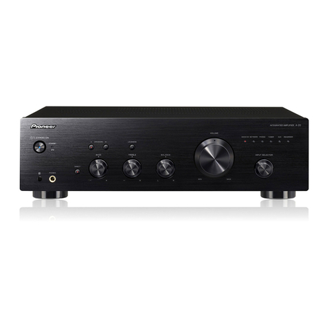
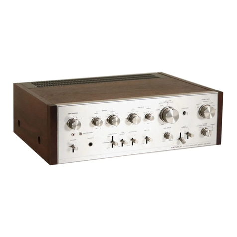
Pioneer SA-530 User manual

(D
rrloNeerl
ORDER
NO.
ARP-104-0
STEREO
AMPLIFIER
SA-53CI
MODEL
SA-530
COMESIN SIX VERSIONS
DISTINGUISHED
AS FOLLOWS:
r Thisservicemanualisapplicableto the KU type.When
repairingtheS.yp, HE,HBandHEZtypes,
please
see
page
2(F 26.
o Cemanueld'instruction
se
refdre
aumodeder69lage,
enfangais.
. Estemanual
deserviciotratadelm6tododeaiusteescritoenespafrol.
CON
TENTS
1. SPEC|FTCATTONS
...........
2. FRONT
PANEL
FACILITIES. ..
3. PARTS
LOCATION
4. DISASSEMBLY
PROCEDURES.
.
5. BLOCK
DIAGRAM
6. CtRCUtTDESCRTPTTONS
.....
7. EXPLODED
VIEW.
..
8. PACKING
4
6
6
9
l0
13
15
17
18
19
20
9. P.C,BOARDS
CONNECTION
DIAGRAM
10. SCHEMATICDIAGRAI\4
11. PARTS
LIST....
12. AOJUSTMENTS
....
REGLAGE
ADJUSTE
13. FOR
S.YP.
HE,HBANDHEZTYPES.
..
PICINEEFI ELECTFICINIC C(IFIPCIFIATION a I, Mesu.o 1-chome, Mesu.o-ku, Tokyo i53, Japan
PIC'NEEFI ELECTFIG'NICB [[rAAl lNC. 1925 E. Dom,nguez Sc.. Long E|esch, Catifo.nia 9081O U.S.A.
pICINEEFI ELECTFIC,NIC lE|.lFlc,PEl N.v. Lulrh6gen-Haven g. 2O3o Ancwenp, Betsium
Ff(INEEFI ELECTFICINIC|B AUATFALIA PYY. lfE. 178-aA4 E|ounda.y Flosd. Bnaesrde, Vcto.,a 3195, Ausc.a a
YG O
l\4AY 1982 Printed
in laoan
Typ€ Volt3!€ Remarka
KU AC l20V only U.S.A.model
sAC110V,
120V,220Vand240V
(Switchable) Generalexportmodel
AC
240Vonly Australiamodel
HE AC22OVand24OV
(Switchable) Europemodel
Hg AC22OVand
240V (Switchable) United Kingdom model
HEZ AC 22OV
and
24OVlswitchable) West
Germanymod€l

1.SPECIFICATIONS
Amplifier
Section
Continuous
average
power
output
is
35
watts*
per
channel,
min.,
at
8ohmsfrom20
hertz
to
20,000
hertz
withn0
more
than
0.05%
total
harmonic
distortion.
Total
Harmonic
Distortion
(20H2
to 20,000H2,
8 ohms,
from
AUX/VlDEOl
17.5watts
per
channel
power
output
. . Nomore
than
0.03%
fntermodulation
Distortion(50H2 : T,OOOHz: 4 : 1,
8ohms,from
AUX/VIDEO)
Continuous
rated
power
output. . Nomore
than
0.0g%
17.5
watts
per
channel
power
output
No
more
than
0.05%
DampingFactor(lkHz,8ohms) .....30
I
nput(Sensitiv
ity/l
mpedance
)
PHONO ...2.5mV/S0kitohms
TUNER,
AUX/VIDEO,
TAPE
1,2/ADAPTOR
... 150mV/50kitohms
Phono
OverloadLevel
(T.H.D.
0.01%,
1,000H2)
PHONO 150mV
Output
(Level)
TAPERECI,2IADAPTOR... 150mV
Speaker .... A,B,A+B,OFF
Frequency
Response
PHONO
(BIAA Equalizationl
20Hz
to 20,000H2
t0.5dB
TUNER,
AUX/VIDEO,
TAPEPLAY
1,2/ADAPTOR
. . . . . 10Hzto60,000Hzt2dB
ToneControl
BASS
. ll0dB (l00Hz)
TREBLE . .110d8
(10,000H2)
LoudnessContour
(Volume
control
setat
-40d8 position) . . .+6dB
(100H2)
Hum
andNoise
(lHF,
short-circuited,A network)
PHONO .....72d8
TUNER,
AUX/VIDEO,
TAPE
PLAY
1,2/ADAPTOR
97dB
Miscellaneous
Power
Requirements . . AC 120V.60H2
Power
Consumption . . 95W
(UL)
Dimensions 420(Wlx 97(Hl
x 275(D)mm
16-9/16(W)
x 3-13/16(H)
x 10-13/16(D)in
Weight
(without
package) . . . . .5.1kg
(11
lb4oz)
FurnishedParts
Operatinglnstructions ......1
NOTE:
Specifietions and the design subject to possible modifiations
wirhout notie due to improvefirents.
'Measured purcuant to the Federal Trade Commission's Trade
Regulation rule on Povmr Output Claims for Amplif iars.

2.FRONT PANELFACILITIES
c POWER
SWTTCH
Push
this switch to turn on or turn off Dower.
@ LOUDNESS
SWTTCH
Set this switch to ON when lastening
at low volume, bass will
be emphasized to compensate for human listening characteristics
and provide natural listening curve.
e TAPE
2/ADAPTOR
SWTTCH
Set this switch to ON when using
a graphic
equalizeror a second
tape deck (or any equipment) connected to the TAPE 2IADAP-
TOR terminals.
(D
powen
METER
The power meter shows the output level in watts when speaker
syst€mswith a nominal impedanceof I ohms havebeenconnected
to the speakerterminals
of thisunit.
@
voluruE
coNTRoL
Slide this control to adiust the output level of the speakersand
the headphones.
Output is minimum at 0 and increases
as the
control is
slided
rightward.
@
seenrERs
sELEcroR
Usethis selectorto selectthe speaker
system.
OFF: Use this seiting when listening through headphones
(no
sound comesout of the speakers.)
A : Sound is heard from speakers
connected.to the A speaker
terminals.
B : Sound is heard from speakers
connected to the B speaker
terminals.
A+B: Sound is heard from speakersconnected to both A and B
speakerterminals.
7;enss
Ar{D
TREBLE
coNTRoLs
Use these controls to adiust the tone. The right one controls
treble and the left one controls bass. Turning knob clockwise
acc€ntuates the bass or treble, and turning counterclockwise
attenuates
the bassor treble.
@
aalerucE
coNTRoL
This control should normally be set to the center
position,
when
the output from the left and right speakersor headphones
is not
the same, adjust by turning the control clockwise or counter-
clockwise.
@ rurucnoN
rNDtcAToRs
Theseindicate the function switch positions.
nD
rurucrroN
swrTcHEs
Usetheseswitches to select
the program sources.
TUNER: Pushwhen listening
to a broadcaston the tuner which
you have
connected to the rearpanel TUNER terminals.
PHONO: Pushwhen playing records
on the turntablewhich you
have connected to the rear oanel PHONO terminals.
TAPE 1 : Push when playing back tapeson a tape deck which you
connected
to the rear
panel
TAPEl terminals.
AUX/VIDEO: Push when using a component which you have
connected to the rear panel AUX/VIDEO ter-
minals.
.D HEADPHONE
JACK
Plug headphones into this jack for private listening through them.
Setthe SPEAKERS
selector
to OFF.
3

3. PARTS LOCATION
Front
Panel
Push
knob B
(
LOUDN
ESS,
TAPE2/ADAPTOR
)
AAD.418
Push
knob
A (POWERI
AAD417
Rotary knob
(SPEAKERS,
BASS,TREBLE,
BALANCE}
AA8.283
Rear
Panel
Tcrminal
4PIT
APE2I
ADAPTOR}
AKB{78
Terminal
6P (INPUT)
AKBO79
Terminal
4P {TAPE1)
AK8-078
TopView
with Bonnet
CaseRemoved
[** ruse
(5A]
AEK-l26
NOTES:
c Partswithout part number cannot be supplied.
o The $ marh found on some component parts indicates the importance of the
safety factor of the part. Therefore, when replacing, be sure to use parts of identical
designation.
c For your Parts Stoch Control, the fast mouing items are indicated with the marks
** and *.
** GENERALLY MOVES FASTER THAN *.
This classification shall be adjusted by eachdistributor because
it depends on model
number, temperature, humidity, etc.
Bonnet case
ANE.353
Front panel assembly
ANM.2O5
I ACsocket
(AC
OUTLETSI
AKP-501
I ACpower
cord
ADG.O52
Terminal
{SPEAKER)
AKE-102
Terminal2P (PHONES)
AKB.O77
AF assembly
Control assembly
AWG{84
i r''w
* LED level
metermodule
AAV.3O3
a*
**
Power transformer (AC 120V)
ATT€95
Rotary switch (S3,
SPEAKERS)
ASE{14
[** Push
switch
(SI,POWER]
ASG-539
[** Fuse
(3.15A]
AEK-124
4

Front
Viewwith FrontPanel
Removed
** Push
switch
(S2,
LOUDNESS,
TAPE2IADAPTOR
I
ASG€02
A ** Push
switch
(Sl,POWER)
ASG-539
** Rotary switch
{S3,
SPEAKERS)
ASEOl4
* Variable
resistor
(VR3,
BASSI
ACT-149
Variable
resistor
(VR4. TREBLEI
ACT-I49
* Variableresistor
(VR1,
VOLUMEI
ACX-109
* Push
switch
(S1,
FUNCTION)
ASG€01
Headphone
jack
AKN.O29
** Lamp assembly
(PL1-PL4I
AEL.l57
* Variable
resistor
(VR2,
BALANCE}
ACT-027
4. DISASSEMBLY
PROCEDURES
Front Panel
Assembly
1. Remove the bonnet case by unscrewing the
three screwson the rear panel.
2. Unscrew the two screws @ frotaing the front
panel assembly in place and remove the four
rotary knobs.
3. Pressdown on the three hooks on the front
panel assembly (indicated by the three arrows)
with a screwdriver to release
the panel holder
and lock. Then, gently pull the paneloutward.
(The bottom of the panel assembly is also
Iocked in three places
by hooks, soremovethe
panelvery carefully.)
Fig.
4-l Removing
thefrontpanel
assembly

5.BLOCK
DIAGRAM
lrso.vl
llsodl
L-CH
r PLAY
AOAPTOR
L
REc
TruA
TAPE I
AUX
rUNER
R-CH
PHONO
TUNER
AUX
4o.3do (AT
ttHr , -l
*T*l oa- -T-+3sv I
TONE CONTROL +22 4V
o2
;-- =
5.i
lT.t...*t
' r----ri
r a.---{Fi
I l.F>-:-''^--l
#
;R-AY
IAP€ {
L REC
swt'rcHEo
TOTAL 8OWHAX
I
I
I
_i
R-CH ( SAME AS THE L CHANNEL)
-rs.zv I
-
a"r,
-a,u,l
-
3a.sv
i
rr___t/o_r_r Iil
UNSWITCH€D
roow MAx
6. CIRCUIT DESCRIPTIONS
Equalizer
Amplifier
The equalizer amp uses a low-noise IC (NJM
4558DX) that contains both the left and right
channel circuits. This IC uses
a balancedpositive/
negative power supply to permit the more than
sufficient permissible input level of 150mV (at
1kHz,0.017dTHD).
Power
Amplifier
This all-stage direct-coupled pure complemen-
tary SEPP circut features a differential amplifier
in the first stage,and incorporates the tone con-
trol circuitsin the NFB loop.
The power stage is a complementary 2-stage
Darlington connection, resulting in an output
power rating of 35W+35W (8Sr, 20Hz-20kHz),
harmonicdistortion of less
than O.O\Vy.

3
2
7.EXPLODED
VIEW
A
B
C
D
_l N
3
2
-l

6
5
4
A
B
D
65
II
I

Parts
List
Mark No. Part No. Description
NO?ES:
c Parts
without part number cannot be
supplied.
c The I marh found on some component parts indicates the importance of the
safety factor of thepart. Therefore, when replacing, be sure to use
parts of identical
designation.
o For your Parts Stoch Control, the fast mouing items are indicated with the marhs
** and *.
** GENERALLY MOVES FASTERTHAN *.
This classification shall be adjusted by each distributor becauseit depends on model
number, temperature, humidity, e
tc.
Mark No. Part No. D€scription
-I
-
1. BBZ30P080FZK
2. AEC-818
** 3. 2SC2579lAl-O*
Qsc2579lAl-Pl*
.?.sc2579lAl-Yl*
** 4. 2SA1',t}4lAl-O*
(2SA1104/A/-P)*
(2SA1104/A/-Y)'
5. ABA-258
A ** 6. Asc-s3g
7. PMZ30P060FMC
8. AAD-417
9. ANM-205
10. AAB-283
11. NKgOFUC
12. 871-010
13. AAD-418
* 14. ATT-895
** 15. AEK-124
rhfe of Q1-O4 shouldhavethe same
value.
Screw
3 x 8
Micawafer
Transistor
(O1,
Cl2)
Transistor
(O3,
04)
Screw
03
Push
switch
(S1,
POWERI
Screw3 x 6
Push
knob
A (POWERI
Frontpanel
assembly
Rotaryknob
(SPEAKERS,
BASS,TREBLE,
BALANCE)
NutMg
NutM7
Push
knobB
(
LOUDN
ESS,
TAPE2/ADAPTOR
}
Power
transformer
(Tl, 120V)
Fuse
(FU1,3.15A)
Fuse
(FU2,
FU3,5A)
Controlassembly
Bonnet
case
ACsocket
(AC
OUTLETSI
Description
21. ADG-052
22. AEC-784
23. ANM-204
24. AAD-419
25. AXC-012
26. PTZ26P080FMC
27. AEC-327
* 28. AAV-303
ACG-O17
AC power cord
Foot assembly
Front panelcover
Pushknob C (TUNER, PHONO,
TAPE1,
AUX}
Slide knob assembly
Screw 2.6 x 8
Strain
relief
LED levelmeter module
Ceramic capacitor (0.01
/AC125V)
Heat
sink
Switch assembly
Rear panel
Mountingplate
Panel
stay
Headphoneassembly
Transformer frame
Chassis
Terminal (GNDI
Front panel base
AF assembly
A
A
51.
52.
53.
54.
55.
56.
57.
58.
59.
60.
61.
A
A
A
A
** 16.
17.
18.
19.
20.
AEK.l26
AWG-084
ANE.353
AKP-501
8. PACKING
Parts
List
Mark No. Part No.
1. AHA-298
2. AR8-476
3. AHE-030
Front rearpad
Operatin
g instructions
(English
)
Packingcase \v
\Y-
-I

I
I
I
DIAGRAM
3
9. P.C. BOARDCONNECTION AFAss'y
A6@ 6@ q@ 6@ o
.
-'
' l*
*f
|';;'"
*+*l
f',.,.,1-
*
'tl I r.,
-------+ r'-*' t: r ' I
."s] f:-.'B.ll*.'., .'.lf fl"*l.
' I I li fs 11r', I
n@
lr;
1./.
f:t" .$'
I
"1 l-' I -
L
ll i* l* I
,ir I I I I
I I 03 2SA'r04rAr
!t
lrlfR)l 'r I
ll.K-l ;
';rqll il l
| | &.t i J r tr
ldn\_a I i i
;::ilg- it r-iir ';l '
i{{1f }'.'''bn'+'l
i'
lllllll,tf;)',
I rrr2 lg
1* rFL-l Icri
'.,' ,i$i":l[]
@@ o@
-l*--t
I .r-, l
I t't]l
I t.'"1
'&:;'
I I I
*'l'11-
;i,t
",r
l r-:O
rTl*
I,,-
'!a
'lrll
j I l* I tF'
--l
r g* I - ll I
L"-i* I l
t--l
'l
i':,
'/'*;' {,t I -'l t i': *:,
=
s-rs.rl,-l ;,.:"1 I I I
,"0"*
It" I .r
- l.;
l" ye
lrrl ,r,,:. .l l**"
l '- | I ll
.'' t:x llli'F"SI,il:
I'r , t'o 13 f?x.lal,, I
'i t r II I I r*+
I'il-,J,-'
I I I q' 11"'l
e+
;Jr"t1tt
,.'
&
&
_[,*r.ki
i;i,Ml.
H;"r,]
_i
-ttt -i,
l/fj'\-"I L r..
. t ,uf i* l)fl1
'&^ 1 l;i". r l*. resi.:::i
1"1
lr;1
T\-i*+
I"";l*iffJ,.r
ll
1l' { rfWI*il
| -;,.i'o
'is
Bez zsczsTgtlt - oc 2saro4rar I
/Al rr ai I
wt i q1)t I
lf.t r, lLt - ::j
"*,,\ 'E'l\_le.,
".1
,.,
I lj: l:x I I l'i"FKl;:l: :
C
qP ql P
il
:?l!?$
-l
'r5 I I
IY ,.+..
I
rY{*
"..1 " .f,r
i4
,.i'6.,
I
l
I
I
3
rI
i-
1
1.1
tl
I
D
2CONTROLAss'
I
-l'"

I
AF Ass'y
6
5
4
s4
POWER
c2 0.0r
/ ac1?5
SWITCHED
TOTAL8OWMAX.
]OOW
|rAX.
cr 0.0t
/ACt?5
swrrcHA
HEADPHCT'IES
JACKAssy
acr2ov
@Hr
l0NTRoL
T65
4
LED LEVELMETER
Ass'y

'l I8
7
External
Apperance
of TransistorsandlCs
2SArtO4/A/
2*2575tN
SlVlrcHAssy
LEVELMETER
tlloDuLE AAV- 3o3
IPHONES
Assy
7
2SC27(F
2SC945A
25D/*!8
B
D
It
rt
ftJt
ury
I8
J-
TA7318P-1 N.!rt4558.OX

13
2
1O.
SCHEMATIC DIAGRAM
LCH
- PLAY
rAPE2l loaplon
r PLAY
TAPEI
[!qmvl *xEL
CONTROLAss,y ll/2)
ACX-t@
VR2 : &LANCE
ACT
- 02?
I
I
I
I nrz cr:
| 2.2*
0.2
-l
VR3 BASS
Afr-i49
W4 TRESLE
acT-r49
r
R2|
56k
RCH PHOSl0
TUNER
auxlvl oEo
Br
TAPE I REC
PLAY
TAPE
2/ADAPTOR
L PLAY
a I iuM45580X
EOUALIZER
AMP
FU
| 3.r3A
AEt- t24
cr.2: AcG'ol7
s4 :rcwEF
ASG-
539
Are- 052A
ACIrcV
@E
UNSWITCHED SUTCHED
1.RESISTORS:
lndicatd in !!,'/.W, 57.
toleranceunlessotherwisenored
k : kll,
M :lvl!!,
(F): l7o.
lG) : ,2oA,
lKl : ' 10%,(M):
I 2o"Atorerance
2.CAPACITORS
Indacatedrncapacity
{!F)/voltage
{V) unressotherwise
noted
p : pF
Indicationwithout voltageis 50V except electrolyticcapactor
3.VOLTAGE,CURRENT
E sisnalvoltasear
38 w l 3a w SlroutputllkHr)
E DC
voltage
(v) atno nPUtsiqnal
Valuein ( ) isDCvoltaoeatrated
power
4 OTHERS:
+rSignat route
@ :
Ad,ustinq
point
The A mark tound
on some
componenl
parts ndicares
the im
podance
ol thesaletyfactor
of the
pa(. Therefore,
whenreptacing,
besre to use
parts
of identical
d€signarion.
:l m/xed cop@itm ond €srsl&s hove ports hum&re
swlTcHEs :
sl-l : FUNCTTON
(TUNER) ON _ qEE
sr-2 : FUNCTTON (PHONO) q! - oFF
sl -3 : FuNcItoN (TAPEI) Ot'r _ qEf
sr -4 : FUNCTTON (AUX/V|oEO) ON - gtE
s2-r : IAPE2IAOAPTOR ON _ qll
S2-2: LOUONESS ON - OFF
53 SPEAKERS OFF
_ A _-E-_ A +B
54 POWER ON _ OFF
The und€rlin6d
indicoi€s
theswitch
positim
cr o.ol
/ actza
02G
D203
WZ-l30 d
MZ
-130
This s the basic schematic diaqram, bur the actua circuit may vary
due to improvements in desiqn I rJ--
I o2or zsDaao
I nect;1a1gP 4202 TAT3|AP-|
COi/
PRESSOR
12
CONTROLAss'y l2/2't
3
D20t wz - oal
MZ
- OBrPL2 4tu3 lPLa
o.@i

6
5
4
NOTE:
The indicated semiconductors are representatiue ones
only. Other alternative semiconductors may be used and
are listed in theparts list.
/2t _
-081 6 |
-o€r I
i
c217
o o@2
AF Ass'y
I
I
Qr,2
25C2579tAt
03,4
2SAlt04/A/
LI
R65
lsrao
cl5
o.3t2.2k
cl9 Rzl
l/$ t6
LcH
Il*-o
RCH J
[-"el
LCH II
sP-B
RCH J
B
I
-
-
02,3 2SA79a
04,5 2SC27O5
06,7 2SC945A
o8,9 2SO43€
oro,r| 2sB56O
POWER
AI\4P
2SD4ita
REGULATOR
53 SPAKERS
ASE
-Or4
s3-2 S3-3
Ol,2 WZ-157
q
MZ
-r37
D3 WZ-23O
or
MZ-23o
c42r43 ACH-49
c4 : A6-Oig
| ^ |
a8. l
t,( \ |
I oFF a+B
_l LEVEL METER MODULE AAV_ 3O3
VR5,6 MEER LEWL ADJ
ACP_
@
65
4
Dg,lO USiO35 q tsi555
or tS2O75
ler6
tg
'"4

-
11
. PARTS LIST
NO?ES:
o When ordering resl'sfors,
first conuert resistance values into code form as shown in
the following examples.
Ex. 1 When there are 2 effective digits (any digit apart from 0), such as 560 ohm
and 47h ohm (tolerance is shown by J = SVo,and K = IO7").
56On 56xLOt 561 .. .. RD%PS
t56[]/
47ha 47x103 473.. .. RDY4PSA\AJ
o.se oR' . . RN2H
@BtrK
Ie 010.. RStPoD@r
Ex. 2 When there are 3 effective digits (such as in high precision metal film resis-
tors).
5.62ksz 562x 100 5621. . . . RN%SRtrGEmF
c The f\ marh found, on some cornponent parts indicates the importance of the
safety factor of the part. Therefore, when replacing, be sure to use
parts of identical
designation.
o For your Parts Stoch Control, the fast moving items are indicated with the marks
** and *-
** GENERALLY MOVES FASTER THAN *.
This classification shallbe adjusted by each distributor because
it depends on model
number , temperature, humidity, etc.
MISCELLANEOUSPARTS
P.C.
BOARD ASSEMBLIES
Mark Part No. Symbol & Descritpion Mark Part No. Symbol & Description
I
AWK.199
AWG-084
OTHERS
Mark Part No.
AF assembly
Control assembly
Symbol & DccraDtion
ccDSL 270J
50
CKDYB
222K50 c207,
c20a
c217,C218
,{\
A*r AEK-124
** AEK-l26
** 2SC2579/A/-O*
QSC2579|Al-Pl*
(25C2579/A/-Y)*
** 2SA1104/A/-O*
(2SA1104/A/-P)*
(2SA11M/A/-Yl.
** ASG-539
ACG-O17
a AKP-501
AEC-818
A ADG-os2
CONTROL
ASSEMBLY
CAPACITORS
Mark Part No.
RESISTORS
Note: Whenordering resistors,conuert the resistance
ualue
into code form, and then rewrite the part no. asbefore.
Mark Part No. Symbol & Doscription
FU1 Fuse
(3.'l5A)
FU2,
FU3 Fuse
(5A)
Ol, 02 Transistor
03, 04 Transistor
S'l Push
switch (POWER)
C1,
C2 Ceramiccapacitor
(0.01/Ac125V)
ACsocket
(AC
OUTLETS)
Mica wafer
AC power cord
(AWG-084)
Symbol & Description
*hfe of 01-O4 should have
the same
value.
* ACX-109
* ACT-O27
* Acr-149
* ACP_090
RD1/4PM
trtrOJ
SEMICONDUCTORS
Mark Part
No.
VR1 Variable
(VOLUME)
VR2 Variable
(BALANCE)
VR3,VR4 Variable
(BASS,
TREBLE}
VRs,VR6 Semi-fixed (METER
LEVEL
ADJ}
R201
-R222, F.225,
R227
-R234
Symbol& Description
A
A
-** 2SD880
** TA7318P-1
* wz-081
(M2-081
l
* wz-130
(MZ-130)
OTHERS
Mark Part No.
0201
0.202
D201
D203
Symbol & Description
CKDYF
473250
coMLA 124K50
CEA
4R7M
sOL
CEAORlM5OL
CEA
R47M5OL
coMAl22K 50
coMA 562K50
coMA 273K50
c201,c202
c205,c206
c213
c214,C215
c216
c209,c210
c211,C212
c203,c204
** ASG-801
** ASG-802
* AAV-303
* AEL-157
51 {FUNCTION)
52 (TAPE2/ADAPTOR,
LOUDNESS)
LED
levelmeter
module
PL1-Pl4 Lampassembly
(TUNER,
PHONO,
TAPE1.AUX)
-15

AF ASSEMBLY
(AWK.I99}
AFassembly
CAPACITORS
Mark Part No. Symbol & Description
Mark Part
No. Symbol & Description
wz-157
lMz-1571
wZ-230
luz-2301
1OE2FD
S4VB2OF
wz-o32
us1
035
(1
S15s5)
(
1
520761
D1,D2
D3
D4,
D5
D6
D7,D8
D9,D10
Svmbol & Descriotion
ACH-239
ACG-o19
CEANL
2R2M
50
CEA
1O1M
sOL
CEA221M 25L
CEA
331MsOL
CEAR33M
sOL
CEANL
OlOM
50
CEA
OlOM
sOL
CEA
22OM25L
CEA
47OM
lOL
CEA47OM
25L
CEA47OM
sOL
CEA
221M1OL
coMA 222J
50
coMA 822J50
ccDsL 150K500
ccDsL 151K
500
ccDsl- 680J
50
ccDsL tolJ 50
ccDsL 221J
50
CKDYF473250
ccDsL 470J
50
C42,C43 Electrolitic
capacitor
(5600/42V1
C44Ceramiccapacitor
(0.01
/
AC150V)
c1,c2
c46
c25,C26,
C37,
C40
c38
cl5,
C16
cl9, C20
cl3.C14
c23,C24,
C39
c5,
c6
c41,
C47
c45
c29.
C30
c7,
c8
c9,c10
c27,C28
c31-C34
c21,
C22
cl7,C18
c3,c4
cl1,C12,
C35.
C36,C48
c65-C68
A*
A* *
*
OTHERS
Mark Part No.
AKB-077
AKB-078
AK8-079
AKE.102
AKH.O16
Headphone
assembly
Mark Part No,
Terminal
2P (PHONES)
Terminal4P (TAPE2/ADAPTOR,
TAPEl
}
Terminal6P (INPUT)
Terminal (SPEAKERS)
Transistor socket
Symbol & Description
AKN-O4,I
Switch
assembly
Mark Part No.
Headphone
jack
Symbol & Description
RESISTORS
Note: Whenordering resistors,
convert the resistancevalue
into code form, and then rewrite the part no. asbefore.
Mark Part No. Svmbol & Description
R55,R56 Wirewound
R80
R63,
R64,R69,R81
R82-R84
R61,R62,R65,R66,
R73-R79
R47-R54,
R57-R60,R70,
R71
R1-R46,
R72
Symbol & Description
** ASE-014
Resistor
Assembly
Mark Part No.
53 Rotary switch (SPEAKERS)
Symbol & Description
ACN-131
R53L271J
RS2L
ootrJ
RS1
L
otraJ
RD%PS
trOtrJ
A BST4PMFL
trtrtrJ
RD74PM
trtrtrJ
SEMICONDUCTORS
Mark Part No.
RD74PM1O2J R85
** NJM4558DX
** 2SA798
** 2SC2705
** 2SC945A
** 2SD438-E"
(25D438-F)*
o1
02,03
04, 05
06, 07
08, 09
010,01
1
258560-E*
(258560-F)
*
*hfe of O8-Q1 1 should have
the samevalue.
** 2SD438 A12
16

12. ADJUSTMENTS
ldleCurrent
1. Set the SPEAKERS switch to the OFF posi
tion, turn the VOLUME all the way down and
then turn power on for about 10 minutes.
2. After the power has been left on for about 10
minutes, confirm that the voltages between
TP4 @ and TPB Q (the left channel) and
between TP1 @ and TP2 O are each be-
tween 0.9mV and 101mV. If avoltage
isbelow
0.9mV, cut the jumper wire of the channel
where the problem exists (jumper wire A for
the left, jumper wire B for the right).
NOTE:
If a voltage is aboue lOImV, chech the circuits to see if
there is a malfunction.
OutputIndicators
(Level
Meter)
1. Removethefront panel
assemblyfollowingthe
directions
in thedisassembly
section.
2. Set the SPEAKERS switch to the A position,
the FUNCTION switch to the AUX setting and
tum all other switches OFF.
And connect an 8S} resistor and AC volt-
meter to the speakeroutput terminal.
Apply a lkHz sine wave, 150mV srgnalto the
AUX terminals and ajustthe VOLUME (VR 1)
so that the voltage at speaker terminal A is
AC8.95V.
Adjust VR 5 (left) and VR 6 (right), the semi-
fixed resistanceof the control assemhlyso that
the output indicator reading is 10 wa'"hs.
Replacing
theAF Assembly
(AWK-199)
P.C.
Board
The AF assembly(AWK-199) used in the SA-
530 can also be usedin the SA-330. When replac-
ing the AF assembly(AWK-199) of SA-530, cut
jumper wire C (connected in parallel with R82,
120ohms).
Jumper
wire C
(Connected
in parallel
with R82, 120ohms)
VRl (VOLUME)
3.
4.
Frontview VRs VR6
Power
switch
Speakers
switch
:D
@@ 0
Jumperwire
B
(Connected
in
parallel
ffi
EU -lYC
FFn d +TP3 withR38,82
ohms)
TPI- /
@c @ o
o
ffiffimoo o
o - L-Cn
ooffi
o
Jumper
wire A
(Connected
in parallel
with R37. 82 ohmsl
LED level
metermodule
l--l te t@ I Do
l;l
FI-If]
-"a@-LJ@ @oTl [--J oo
/-\ /--\ ^
\__J \__J v
Fig.12-1 Adjustment
of idlecurrentandoutput indicator
17

12.REGLAGE
Gourantd6watt6
L. R6gler sur OFF le s6lecteur d'enceintes
(SPEAKERS), r6duire au ma:rimum la com-
mande de VOLUME et placer sous tension
pendant 10 minutes environ.
2. Aprds ces quelque 10 minutes, v6rifier si les
tensions entre TP4 (+) et TpB (- ) (le canal
gauche)
et entreTP1 (+) et Tp2 (- ) setrouvent
respectivemententre 0,9mV et 101mV. Si la
tension est inf6rieure i 0,gmV, couper la liai-
son du canal oi le probldme se manifeste
(liaision A pour le gauche ou liaison B pour le
droit).
Remarque:
Si une tension est eupdrieure d lO1mV, fhrifier la pr1ence
dventuelle d'une ddfaillance dans les circuits.
Indicaburs
de
sortie
(Niveau)
1. D6poser I'ensembledu panneau avant en
suivant
lesexplications
delasection
ded6mon-
tage.
2.
3.
4.
Placerle s6lecteurd'enceintes (SPEAKERS) a
la position A, le s6lecteur
de fonction (FUNC-
TION) d la position AUX et toutes lesautres
commandes
surOFF.
Et brancher une r6sistance de 8Q et un voit
m6tre en CA aux bornes de sorties des en-
ceintes.
Appliquer une onde sinusoidale de 1kHz, un
signal de 150mV aux bornes AUX et r6gler la
commande de VOLUME (VR1) de sorte que
la tensioni la bome d'enceinte
A soir 8,9bV en
courant alternatif.
Ajustar VTb (gauche) et VR6 (droit), la
rdsistance semi-fixe de I'ensemble de contr6le
de sorte que la lecture de I'indicateur de sortie
soit de 10 watts.
Remplacement
de la plaquette
de circuit imprim6
Ensemble
AF (AWK-199)
L'ensemble AF (AWF-199) utilis6 dans le SA-
530, peut 6galement
servirdans
le SA-330.Lors du
remplacement de l'ensemble AF (AWK-199) du
SA-530, couper la liaison C (raccord6e
enparalldle
avecle F"82,
LzOohms).
Liaison
C (Raccord6e
en paralldle
avecle R82, 120ohms)
/A/i\=
3f) Kr) [t .l Liaison
B
(raccord6e
en
\7 \7 parattCte
avecteR38,82 ohmsl
rEN _TP4 TPI
[;+F;+;l=
oC
_o
hd hrdbudo o
(E
@o _ cana
oo- % tEEd oauche
Doool o - /
Liaison A (raccordde
en paralldle
avec
le R37,82 ohms)
Module
de I'indicateur
de niveau
ddiodes
LED
I l--l te r@ 3 Dot;l
'I u
r t--l I t( |
llllll
0 ",^@l r@ @
oT-lU
O oE l---l oo
f--\ F\ ^
\__J \-/ v
Fig.
12-1 R6glageducourant
d6watt6
etdel,indicateur
de
sortie
VB1
(VOLUMEI
vistadefrente VRs VR6
Selectorde poder
Selectorde altavoces
1E}

12.ADJUSTE
Corrientereactiva
1. Ponerel selectorde altavoces
(SPEAKERS)en
la posici6n OFF, reducir completamente el
VOLUMEN y conectar
la alimentaci6ndurante
unos10 minutos.
2. Despu6s
de haber dejado conectada
la alimen-
taci6n duranteunos 10 minutos, confirmar que
las tensionesentre TP4 (+) y TP3 (- ) (canal
izquierdo) y entre TP1 (+) y TP2 (- ) est6n
entre 0,9mV y 101mV. Si Ia tensi6n est6por
debajo de 0,9mV, cortar el cable de conexi6n
provisional del canal donde exista el problema
(cable de conexi6n provisional A para el
izquierdo,y cable
B parael derech).
NOTA:
Si la tensi6n estd por encima de los 1O0mV, comprobar
los circuitos para uer si existe algin malfuncionamiento.
Indicadores
de
salida
(Medidor
denivel)
1. Extraerel conjuntodepanel
frontal seiguiendo
lasinstrucciones
de la secci6n
dedesmontaje.
2.
3.
4.
Poner el selectorSPEAKERS en la posici6nA,
el selector de funci6n (FUNCTION) en la
posici6n AUX, y poner todos los demasinter-
ruptoresen las
posiciones
OFF.
Entonces, conectar un presistor de Sohmios
y el voltimetro de CA al terminal de salida
de altavoz.
Aplicar unda onda sinusoidal de lkHz, y una
seflal de 150mV a los terminales AUX y
ajustar el VOLUMEN (VRl) de modo que la
tensi6n en el terminal A de altavoz sea de
8,95V
CA.
Ajustar VR5 (izquierdo) y VR6 (derecho),en
Ia resistencia semifija del conjunto de control
de modo que el indicador de salidaindique 10
vatios.
Reemplazo
deltableroPC
delconjuntoAF
(AWK-199)
El conjunto AF (AWK-199) utilizado en el SA-
530 tambi6n puede
utilizarseenel SA-330.Cuando
se reemplaceel conjunto AF (AWK-199) del SA-
530, cortar el cable de conexi6n provisional C
(conectado en paralelo con la R82, 120 ohmios).
Cable
deconexi6n provisional
C
(connectado
en paralelo
con la R82, 120 ohmiosl
,D
@g Cablede conexi6n provisional B
(connectado
en paralelo
con la R38,82 ohmiosl
-TP4 TPI------r
d +TP3 TP2{ d
VR1
(VOLUME)
vista de frente VRs VR6
Sdlecteur
depouvoir
S6lecteur
d'enceintes
o c g_o
o
ffiffimoo o
Cabledeconexi6nprovisional
A
(connectado
en paralelo
con la R37, 92 ohmiosl
M6dulo del medidorde nivel
del LED
n tet@3 !ol;l
"n
l-l c
50-L_f@ @o oE l----hoo
CCo
Fig.
12-1 Ajuste
dela
corrientereactiva
y delindicador
de
salida
IU

13. FOR S,YP,
HE,
HB AND HEZ TYPES
13.1 CONTRAST
PARTS
SA-530/S,
YP,HE, HBandHEZ types
are
the sameastheSA-530/KU
typeexceptfor following
sections.
MISCELLANEOUS
PARTS
Mark Symbol & Description Part No.
KUtypo S type YP type HE typo HB type HEZ type
A*
A*
A*
A**
A**
A**
A**
A**
a**
A**
a**
A
A
A
A
Tl Power
transformer
(120V1
T1 Power transformer (22OV
,240yl
Tl Power
transformer
(1
10V, .|20V,
220V,240V1
FUl Fuse
(3.15A)
FU2,FU3 Fuse
(5A)
FU1,FU4 Fuse
(1.641
FUl Fuse
(T1A)
FU2, FU3 Fuse
(T2.5A)
FU4 Fuse
(T2.5A)
51 Push
switch (POWER)
52 Voltage selectorswitch
Cl Ceramiccapacitor(0.01/ACl25V)
C1 Ceramiccapacitor(0.01/AC250Vl
C3 Ceramic capacitor
Strain
relief
AC power cord
AC socket
{AC OUTLETS}
Screw(For voltage
selector
switch)
Tapping screw
(For
SPEAKERSterminall
Operatinginstructions
(English
)
Operating
instructions
(English
/German/French
/
ltalian
)
Operating
instructions
(German)
Operating
instructions
(Spanish
)
Packing
case
ATT.895
AEK-124
AEK-126
ASG-539
ACG-O17
;;;;;;
ADG-052
AKP-501
ARB-476
AHE-O3O
ATT-897
AEK-126
AEK.121
ASG-539
AKX-063
ACG-001
ADG-060
AKP-sO1
MTZ3OPlOOFZK
ARB.481
ARC-021
At{E-036
AEK.4O2
AEK-403
ASG-522
olo-oo'
ADG.067
ATT-896
ARB.481
AHE-036 |
AEK.4O2
AEK-403
AKE4O3
ASG-522
^J:":l
ADG-065
AKP-502
ATT-896
ARE.O3O
AHE.O36
ATT-896
AEK4O2
AEK-403
ASG-522
o"coft
ADG.O63
AKP.5O3
ARB-481
AHE-036
ATT.896
AEK-402
AEK-403
AEK4O3
ASG.522
ACG-001
coMA 223K
ADG-065
:::::i
ABA-115
ARC-016
AHE.O36
50
P.C.
BOARD
ASSEMBLY
Mark Symbol& Description Part No.
KU type sryp€ YP type HE
Upe HBtypo HEZtype
AF assembly AWK-199 AWK.202
LINE VOLTAGE SELECTTON
(FOR
HE,
HB,HEZ
Line voltage can be changedasfollows:
1. Disconnect
the AC power cord.
2. Remove
the bonnet case.
3. Takeout the fusefrom the P.C.board.
4. Re-install the fuse in the correct voltage
indication.
5. Stick the line voltage lable on the rear panel.
Description Part No.
TYPES}
220V label
240V label AAX-193
AAX.192
Heatsink
AF assembly
Table of contents
Other Pioneer Amplifier manuals

Pioneer
Pioneer SA-V210 User manual

Pioneer
Pioneer A-109 User manual

Pioneer
Pioneer GM-D1004 User manual

Pioneer
Pioneer VSA-1000 User manual

Pioneer
Pioneer A-447 User manual

Pioneer
Pioneer GM-3100T User manual

Pioneer
Pioneer C-AX10 User manual

Pioneer
Pioneer GM-X374 User manual

Pioneer
Pioneer A-109 User manual

Pioneer
Pioneer M-F10 User manual

Pioneer
Pioneer GM-6400F/XJ/UC User manual

Pioneer
Pioneer A-443 User manual

Pioneer
Pioneer A-616 User manual

Pioneer
Pioneer A-110 User manual

Pioneer
Pioneer Premier PRS-D1100M User manual

Pioneer
Pioneer GM-X944 User manual

Pioneer
Pioneer A-302R User manual

Pioneer
Pioneer A-8 User manual

Pioneer
Pioneer SA-6500 User manual

Pioneer
Pioneer GM-D8400M - Amplifier User manual