manuals.online logo
Brands
  1. Home
  2. •
  3. Brands
  4. •
  5. Pioneer
  6. •
  7. Car Receiver
  8. •
  9. Pioneer MEH-P6550 User manual

Pioneer MEH-P6550 User manual

30˚
7
182
53
12
3
4
<KSNNF/02K00000>
MEH-P6550
Printed in Japan
<CRD3741-A> ES
5
6
Fig. 4
10
11
13
12
8
9
Fig. 2
Fig. 1 Fig. 3 Fig. 5
Fig. 6
Fig. 7
INSTALLATION MANUAL
MANUAL DE INSTALAÇÃO
This product conforms to new cord colors.
As cores dos fios deste produto seguem um novo
padrão de cores.
14
15 16
17
18
Fig. 9
Fig. 10Fig. 8
Nota:
• Antes de instalar o aparelho, conecte os fios tem-
porariamente, certificando-se de que todos este-
jam conectados corretamente, e que o aparelho e
o sistema completo funcionem adequadamente.
• Utilize somente as peças incluídas com o aparel-
ho para garantir uma instalação correta. O uso de
peças não autorizadas pode causar defeitos.
• Consulte o seu revendedor mais próximo se for
necessário fazer perfurações ou outras modifi-
cações no veículo para a instalação.
• Instale o aparelho de modo que não fique no
caminho do motorista nem onde possa causar
danos aos passageiros no caso de uma parada
repentina, como numa freada de emergência.
• O laser de semicondutor será avariado se for
sobreaquecido. Portanto, não instale o aparelho
num lugar que fique muito quente como por
exemplo, perto da saída do aquecedor.
• Se o ângulo de instalação exceder de 30° desde a
horizontal, o aparelho pode não atingir sua per-
formance ótima (Fig. 1).
Montagem dianteira/traseira DIN
Este aparelho pode ser instalado apropriadamente
na “Dianteira” (montagem convencional dianteira
DIN) ou na “Traseira” (montagem traseira DIN,
utilizando os orifícios de parafusos roscados nos
lados do chassi do aparelho). Para maiores detal-
hes, refira-se aos seguintes métodos de instalação
ilustrados.
Montagem dianteira DIN
Instalação com uma bucha de borracha
(Fig. 2)
1. Painel de instrumentos
2. Sujeitador
Depois de inserir o sujeitador no painel de instru-
mentos, escolha as lingüetas apropriadas de acor-
do com a espessura do material do painel de
instrumento, e dobre-as.
(Instale o mais firme possível usando as lingüetas
superior e inferior. Para fixar, dobre as lingüetas
90 graus.)
3. Bucha de borracha
4. Parafuso
Remoção do aparelho (Fig. 3) (Fig. 4)
5. Armação
6. Insira o pino de liberação no orifício no fundo da
armação e puxe-o para fora para remover a
armação.
(Quando recolocar a armação, aponte o lado com
a ranhura para baixo e fixe-a.)
7. Insira as chaves de extração fornecidas no aparel-
ho, como mostrado na figura, até que elas se
encaixem em posição. Enquanto mantém as
chaves pressionadas contra os lados do aparelho,
puxe o aparelho para fora.
Montagem traseira DIN
Instalação utilizando os orifícios de
parafuso no lado do aparelho
(Fig. 5) (Fig. 6) (Fig. 7)
1. Retire a armação.
8. Armação
9. Insira o pino de liberação no orifício no fundo da
armação e puxe-o para fora para remover a
armação.
(Quando recolocar a armação, aponte o lado com
a ranhura para baixo e fixe-a.)
2. Fixação do aparelho no suporte de
montagem de rádio da fábrica.
10. Escolha a posição onde os orifícios de parafusos
do suporte e os orifícios dos parafusos do com-
ponente principal fiquem alinhados (ajustados), e
aperte os parafusos em 2 lugares em cada lado.
Utilize parafusos reforçados (5 ×8 mm), ou para-
fusos embutidos (5 ×9 mm), dependendo da
forma dos orifícios para os parafusos no suporte.
11. Parafuso
12. Suporte de montagem de rádio da fábrica
13. Painel de instrumentos ou consolo
Instalação <PORTUGUÊS (B)>
Note:
• Before finally installing the unit, connect the
wiring temporarily, making sure it is all connect-
ed up properly, and the unit and the system work
properly.
• Use only the parts included with the unit to
ensure proper installation. The use of unautho-
rized parts can cause malfunctions.
• Consult with your nearest dealer if installation
requires the drilling of holes or other modifica-
tions of the vehicle.
• Install the unit where it does not get in the dri-
ver’s way and cannot injure the passenger if there
is a sudden stop, like an emergency stop.
• The semiconductor laser will be damaged if it
overheats, so don’t install the unit anywhere hot
— for instance, near a heater outlet.
• If installation angle exceeds 30° from horizontal,
the unit might not give its optimum performance.
(Fig. 1)
DIN Front/Rear-mount
This unit can be properly installed either from
“Front” (conventional DIN Front-mount) or
“Rear” (DIN Rear-mount installation, utilizing
threaded screw holes at the sides of unit chassis).
For details, refer to the following illustrated
installation methods.
DIN Front-mount
Installation with the rubber bush (Fig. 2)
1. Dashboard
2. Holder
After inserting the holder into the dashboard,
then select the appropriate tabs according to the
thickness of the dashboard material and bend
them.
(Install as firmly as possible using the top and
bottom tabs. To secure, bend the tabs 90
degrees.)
3. Rubber bush
4. Screw
Removing the Unit (Fig. 3) (Fig. 4)
5. Frame
6. Insert the release pin into the hole in the bottom
of the frame and pull out to remove the frame.
(When reattaching the frame, point the side with
a groove downwards and attach it.)
7. Insert the supplied extraction keys into the unit,
as shown in the figure, until they click into place.
Keeping the keys pressed against the sides of the
unit, pull the unit out.
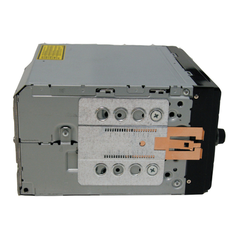
DIN Rear-mount
Installation using the screw holes on
the side of the unit (Fig. 5) (Fig. 6) (Fig. 7)
1. Remove the frame.
8. Frame
9. Insert the release pin into the hole in the bottom
of the frame and pull out to remove the frame.
(When reattaching the frame, point the side with
a groove downwards and attach it.)
2. Fastening the unit to the factory
radio mounting bracket.
10. Select a position where the screw holes of the
bracket and the screw holes of the head unit
become aligned (are fitted), and tighten the
screws at 2 places on each side. Use either truss
screws (5 ×8 mm) or flush surface screws
(5 ×9 mm), depending on the shape of the screw
holes in the bracket.
11. Screw
12. Factory radio mounting bracket
13. Dashboard or Console
Installation <ENGLISH> Installing the Remote Control Unit <ENGLISH>
Fitting the Remote Control Unit
Precaution:
• Press the remote control unit onto the mounting base until it clicks into place.
Fitting horizontally (Fig. 8)
Fitting vertically (Fig. 9)
Installation Using the Mounting Base (Fig. 10)
Precaution:
• To avoid it being a hindrance to driving, always install the remote control unit to the passenger’s
side – not the driver’s side.
• Install the mounting base so that the remote control unit is slanting upwards at an angle when
fitted.
• Before using double-sided tape, clean off any dirt on the surface to which the double-sided tape is
to be attached.
14. Mounting Base
15. Double-sided tape
16. Not used
17. Used
18. Passenger seat
Instalação do Controle Remoto <PORTUGUÊS (B)>
Colocação do controle remoto
Precaução:
• Pressione a unidade do controle remoto na base de montagem até que se encaixe em posição.
Colocação horizontal (Fig. 8)
Colocação vertical (Fig. 9)
Instalação com a base de montagem (Fig. 10)
Precaução:
• Para evitar que o controle remoto perturbe a condução do automóvel, sempre instale-o no lado do
passageiro, e não no lado do motorista.
• Instale a base de montagem de modo que a unidade do controle remoto fique inclinado para cima
num ângulo quando montado.
• Antes de utilizar a fita adesiva de duas faces, remova qualquer sujeira da superfície na qual fixará a
fita.
14. Base de montagem
15. Fita adesiva de duas faces
16. Não usado
17. Usado
18. Assento do passageiro
+
≠
+
≠
+
≠
+
≠
24. Right
Gray
23. Left
.
14. Connecting cords with RCA pin plugs
(sold separately)
17. System remote control
32. Perform these connections when using
the optional amplfier.
15. Power amp
(sold separately)
1. This Product
4. IP-BUS input (Blue)
3.Antenna jack 5. Multi-CD player
(sold separately)
6. IP-BUS cable
13. Fuse
30. Subwoofer 30. Subwoofer
Yellow/black
If you use a cellular telephone, connect it via the
Audio Mute lead on the cellular telephone. If not,
keep the Audio Mute lead free of any connections.
7.
Blue
When the source is selected the tuner, a control signal is
output.
ToAuto-antenna relay control terminal.
If the car features a glass antenna, connect to the antenna
booster power supply terminal (max. 300 mA 12 V DC).
8.
Yellow
To terminal always supplied
with power regardless of
ignition switch position.
9.
Black (ground)
To vehicle (metal) body.
12.
Blue/white
When the source is switched ON,
a control signal is output.
To system control terminal of the
power amp (max. 300 mA 12 V
DC).
16.
Front speaker18.
White19.
White/black20.
Green26.
Green/black27.
Front speaker18.
Rear speaker25. Rear speaker25.
21.
Gray/black22.
Violet28.
Violet/black29.
With a 2 speaker system, do not connect
anything to the speaker leads that are not
connected to speakers.
31.
Orange/white
To lighting switch terminal.
11.
Red10.
To electric terminal controlled by
ignition switch (12 V DC) ON/OFF.
2. Subwoofer output or
Non-fading output
Note:
• This unit is for vehicles with a 12-volt battery
and negative grounding. Before installing it in a
recreational vehicle, truck, or bus, check the bat-
tery voltage.
• To avoid shorts in the electrical system, be sure
to disconnect the ≠battery cable before begin-
ning installation.
• Refer to the owner’s manual for details on con-
necting the power amp and other units, then
make connections correctly.
• Secure the wiring with cable clamps or adhesive
tape. To protect the wiring, wrap adhesive tape
around them where they lie against metal parts.
• Route and secure all wiring so it cannot touch
any moving parts, such as the gear shift, hand-
brake and seat rails. Do not route wiring in
places that get hot, such as near the heater outlet.
If the insulation of the wiring melts or gets torn,
there is a danger of the wiring short-circuiting to
the vehicle body.
• Don’t pass the yellow lead through a hole into
the engine compartment to connect to the battery.
This will damage the lead insulation and cause a
very dangerous short.
• Do not shorten any leads. If you do, the protec-
tion circuit may fail to work when it should.
• Never feed power to other equipment by cutting
the insulation of the power supply lead of the
unit and tapping into the lead. The current capac-
ity of the lead will be exceeded, causing over-
heating.
• When replacing fuse, be sure to use only fuse of
the rating prescribed on the fuse holder.
• Since a unique BPTL circuit is employed, never
wire so the speaker leads are directly grounded
or the left and right ≠speaker leads are com-
mon.
• Speakers connected to this unit must be high-
power types with minimum rating of 50 W and
impedance of 4 to 8 ohms. Connecting speakers
with output and/or impedance values other than
those noted here may result in the speakers
catching fire, emitting smoke, or becoming dam-
aged.
• When an external power amp is being used with
this system, be sure not to connect the blue/white
lead to the amp’s power terminal. Likewise, do
not connect the blue lead to the power terminal
of the auto-antenna. Such connection could cause
excessive current drain and malfunction.
• To avoid short-circuiting, cover the disconnected
lead with insulating tape. Especially, insulate the
unused speaker leads without fail. There is a pos-
sibility of short-circuiting if the leads are not
insulated.
• To prevent incorrect connection, the input side of
the IP-BUS connector is blue, and the output side
is black. Connect the connectors of the same col-
ors correctly.
• If this unit is installed in a vehicle that does not
have an ACC (accessory) position on the ignition
switch, the red lead of the unit should be con-
nected to a terminal coupled with ignition switch
ON/OFF operations. If this is not done, the vehi-
cle battery may be drained when you are away
from the vehicle for several hours.
• The black lead is ground. Please ground this lead
separately from the ground of high-current prod-
ucts such as power amps.
If you ground the products together and the
ground becomes detached, there is a risk of dam-
age to the products or fire.
• Cords for this product and those for other prod-
ucts may be different colors even if they have
the same function. When connecting this prod-
uct to another product, refer to the supplied
Installation manuals of both products and con-
nect cords that have the same function.
Connecting the Units
ACC position
A
C
C
O
N
S
T
A
R
T
O
F
F
O
N
S
T
A
R
T
O
F
F
No ACC position
<ENGLISH>
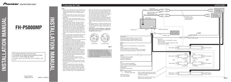
Connection Diagram (Fig. 11)
1. This Product
2. Subwoofer output or Non fading output
3. Antenna jack
4. IP-BUS input (Blue)
5. Multi-CD player (sold separately)
6. IP-BUS cable
7. Yellow/black
If you use a cellular telephone, connect it via the
Audio Mute lead on the cellular telephone. If not,
keep the Audio Mute lead free of any connections.
8. Blue
When the source is selected the tuner, a control
signal is output. To Auto-antenna relay control
terminal. If the car features a grass antenna,
connect to the antenna booster power supply
terminal (max. 300 mA 12 V DC).
9. Yellow
To terminal always supplied with power regard-
less of ignition switch position.
10. Red
To electric terminal controlled by ignition switch
(12 V DC) ON/OFF.
11. Orange/white
To lightning switch terminal.
12. Black (ground)
To vehicle (metal) body.
13. Fuse
14. Connecting cords with RCA pin plugs (sold sepa-
rately)
15. Power amp (sold separately)
16. Blue/white
When the source is switched on, a control signal
output. To system control terminal of the power
amp (max. 300 mA 12 V DC).
17. System remote control
18. Front speaker
19. White
20. White/black
21. Gray
22. Gray/black
23. Left
24. Right
25. Rear speaker
26. Green
27. Green/black
28. Violet
29. Violet/black
30. Subwoofer
31. With a 2 speaker system, do not connect anything
to the speaker leads that are not connected to
speakers.
32. Perform these connections when using the
optional amplifier.
Fig. 11
Nota:
• Este aparelho foi concebido para veículos com uma
bateria de 12 Volts e conexão à terra negativa. Antes
de instalar o aparelho num veículo recreativo, cam-
inhão ou ônibus, verifique a voltagem da bateria.
• Para evitar curto-circuitos no sistema elétrico,
certifique-se de desconectar o cabo ≠da bateria
antes de iniciar a instalação.
• Consulte o manual do proprietário para maiores detal-
hes sobre como conectar um amplificador de potência
e as outras unidades, e faça as conexões corretamente.
• Prenda os fios com braçadeiras de cabo ou fita adesi-
va. Para proteger os fios, enrole fita adesiva em volta
deles onde eles fiquem contra partes metálicas.
• Encaminhe e segure todos os fios de modo que
não toquem em partes móveis, tais como a alavan-
ca de mudanças de marcha, alavanca do freio de
estacionamento e trilhos dos assentos. Não encam-
inhe os fios em lugares que ficam muito quentes,
tais como perto da saída do aquecedor. Se o isola-
mento dos fios derreter-se ou cortar-se, há o peri-
go de curto-circuito com a carroçaria do veículo.
• Não passe o fio amarelo através do orifício no
compartimento do motor para conectá-lo à bate-
ria. Isso danificará o isolamento do fio e causará
um curto-circuito muito perigoso.
• Não deixe os fios entrarem em curto-circuito. Se isso
ocorrer, o circuito de proteção poderá não funcionar.
• Nunca forneça energia a outros equipamentos cortan-
do o isolamento do fio de alimentação do componente
e fazendo uma emenda. Acapacidade de corrente do
fio será excedida, causando um sobreaquecimento.
• Ao substituir o fusível, certifique-se de utilizar
somente um fusível com a potência nominal pre-
scrita no porta-fusíveis.
• Como se emprega um único circuito BPTL,
nunca faça a instalação elétrica de modo que os
fios dos alto-falantes fiquem diretamente conec-
tados à terra nem que os fios esquerdo e direito
≠dos alto-falantes fiquem em comum.
• Os alto-falantes conectados a este componente devem
ser do tipo de alta potência, com uma potência nomi-
nal mínima de 50W e uma impedância de 4 a 8 ohms.
Conectar alto-falantes com valores de saída e/ou
impedância diferentes dos especificados pode causar o
fogo, emissão de fumaça ou danos aos alto-falantes.
• Ao utilizar um amplificador de potência externo
com este sistema, certifique-se de não conectar o
fio azul/branco do terminal de potência do ampli-
ficador. Do mesmo modo, não conecte o fio azul
do terminal de potência da antena automática. Tal
conexão poderia causar uma drenagem de cor-
rente excessiva e um conseqüente mau funciona-
mento.
• Para evitar curto-circuitos, cubra o condutor
desconectado com fita isolante. Especialmente,
isole os condutores de alto-falante não usados.
Há a possibilidade de curto-circuito se os condu-
tores não forem isolados.
• Se este componente for instalado num veículo
não equipado com uma posição ACC (acessório)
na chave de ignição, o fio vermelho do compo-
nente deve ser conectado ao terminal acoplado
com as operações de ligar/desligar da chave de
ignição. Se isso não for feito, a bateria do veículo
pode descarregar-se quando você ficar fora do
veículo durante várias horas.
• O cabo preto é para a terra. Aterre este cabo sep-
aradamente da terra de produtos de corrente alta
como amplificadores de potência.
Se você ligar aterrar os produtos juntos e a terra
for desligada, haverá o risco de danos aos produ-
tos ou incêndio.
• Os cabos para este aparelho e os de outros com-
ponentes podem ter cores diferentes, mesmo que
tenham a mesma função. Quando conectar este
aparelho a um outro aparelho, consulte os manu-
ais de instalação de ambos os aparelhos e conecte
os cabos que tenham a mesma função.
Conexão das unidades
Posição ACC
A
C
C
O
N
S
T
A
R
T
O
F
F
O
N
S
T
A
R
T
O
F
F
Sem posição ACC
Diagrama de Conexão (Fig. 11)
1. Este componente
2. Saída de subwoofer ou saída sem atenuação
3. Jaque para antena
4. Entrada IP-BUS (Azul)
5. Multi-CD player (vendido separadamente)
6. Cabo IP-BUS
7. Amarelo/preto
Se você utilizar um telefone celular, conecte-o
através do fio Audio Mute no telefone celular.
Caso contrário, não conecte o fio Audio Mute a
nada.
8. Azul
Quando a fonte selecionada é o sintonizador, um
sinal de controle é emitido. Ao terminal de cont-
role de relé de antena automática. Se o carro tiver
uma antena de vidro, conecte o terminal de ali-
mentação do reforçador de antena (máx. 300 mA
12 V CC).
9. Amarelo
Ao terminal sempre fornecido com energia inde-
pendentemente da posição da chave de ignição.
10. Vermelho
Ao terminal controlado pelo ligar/desligar da
chave de ignição (12 V CC).
11. Laranja/branco
Ao terminal do interrupor de iluminação
12. Preto (terra)
À carroçaria (metal) do veículo.
13. Fusível
14. Conexão dos cabos com plugues de pino RCA
(vendido separadamente).
15. Amplificador de potência (vendido separada-
mente)
16. Azul/branco
Quando a fonte é ligada, um sinal de controle é
emitido. Ao terminal de controle do amplificador
de potência (máx. 300 mA 12 V CC).
17. Controle remoto de sistema
18. Alto-falante dianteiro

19. Branco
20. Branco/preto
21. Cinza
22. Cinza/preto
23. Esquerda
24. Direita
25. Alto-falante traseiro
26. Verde
27. Verde/preto
28. Violeta
29. Violeta/preto
30. Subwoofer
31. Com um sistema de 2 alto-falantes, não conecte
nada aos fios de alto-falante que não estão conec-
tados a alto-falantes.
32. Realize estas conexões quando utilizar o amplifi-
cador opcional.
<PORTUGUÊS (B)>

Other manuals for MEH-P6550

2

Other Pioneer Car Receiver manuals

Pioneer AVIC-X3 II User manual

Pioneer

Pioneer AVIC-X3 II User manual

Pioneer DEH-P80MP User manual

Pioneer

Pioneer DEH-P80MP User manual

Pioneer FH-P6600R User manual

Pioneer

Pioneer FH-P6600R User manual

Pioneer DEH-30MP User manual

Pioneer

Pioneer DEH-30MP User manual

Pioneer DEH-50UB User manual

Pioneer

Pioneer DEH-50UB User manual

Pioneer Premier DEH-P760MP User manual

Pioneer

Pioneer Premier DEH-P760MP User manual

Pioneer DEH-P7900UB User manual

Pioneer

Pioneer DEH-P7900UB User manual

Pioneer X-EM21 User manual

Pioneer

Pioneer X-EM21 User manual

Pioneer DEH-X6600DAB User manual

Pioneer

Pioneer DEH-X6600DAB User manual

Pioneer DEH-P690UB - Premier Radio / CD User manual

Pioneer

Pioneer DEH-P690UB - Premier Radio / CD User manual

Pioneer DEH-P80MP User manual

Pioneer

Pioneer DEH-P80MP User manual

Pioneer KEH-P4020 - Radio / Cassette Player User manual

Pioneer

Pioneer KEH-P4020 - Radio / Cassette Player User manual

Pioneer DEH-X5800BT User manual

Pioneer

Pioneer DEH-X5800BT User manual

Pioneer MEH-P9000R User manual

Pioneer

Pioneer MEH-P9000R User manual

Pioneer DEH-X7500HD User manual

Pioneer

Pioneer DEH-X7500HD User manual

Pioneer MVH-159UI User manual

Pioneer

Pioneer MVH-159UI User manual

Pioneer DVH-340UB User manual

Pioneer

Pioneer DVH-340UB User manual

Pioneer MVH-X380BT User manual

Pioneer

Pioneer MVH-X380BT User manual

Pioneer DEH-3900BT User manual

Pioneer

Pioneer DEH-3900BT User manual

Pioneer AVH-P3200BT User manual

Pioneer

Pioneer AVH-P3200BT User manual

Pioneer XR-P670F User manual

Pioneer

Pioneer XR-P670F User manual

Pioneer AVH-310EX User manual

Pioneer

Pioneer AVH-310EX User manual

Pioneer CDX-FM1287 - CD Changer User manual

Pioneer

Pioneer CDX-FM1287 - CD Changer User manual

Pioneer DEH-8300SD User manual

Pioneer

Pioneer DEH-8300SD User manual

Popular Car Receiver manuals by other brands

R/Evolution Revosys X500 operating manual

R/Evolution

R/Evolution Revosys X500 operating manual

Silvercrest KH 2375 operating instructions

Silvercrest

Silvercrest KH 2375 operating instructions

Sound Storm SD320 user manual

Sound Storm

Sound Storm SD320 user manual

Sound Storm SD730M user manual

Sound Storm

Sound Storm SD730M user manual

PowerAcoustik PTID-3200 owner's manual

PowerAcoustik

PowerAcoustik PTID-3200 owner's manual

JVCKENWOOD KD-T812BT instruction manual

JVCKENWOOD

JVCKENWOOD KD-T812BT instruction manual

Audiosystem AS 100 EVO user manual

Audiosystem

Audiosystem AS 100 EVO user manual

BOSSCO MR1630UA user manual

BOSSCO

BOSSCO MR1630UA user manual

BASSFACE Bt200.1 manual

BASSFACE

BASSFACE Bt200.1 manual

StarTech.com LD-857-2DIN installation instructions

StarTech.com

StarTech.com LD-857-2DIN installation instructions

Boss Audio Systems ELITE 455BRGB user manual

Boss Audio Systems

Boss Audio Systems ELITE 455BRGB user manual

JVC KD-G521 instructions

JVC

JVC KD-G521 instructions

Hafler SE-130 owner's manual

Hafler

Hafler SE-130 owner's manual

Panasonic CQ-DF701W operating instructions

Panasonic

Panasonic CQ-DF701W operating instructions

Clarion VX404E Quick start guide & installation manual

Clarion

Clarion VX404E Quick start guide & installation manual

Blaupunkt Lexington CM84 Owner's record

Blaupunkt

Blaupunkt Lexington CM84 Owner's record

JVC GET0721-001A instruction manual

JVC

JVC GET0721-001A instruction manual

JVC KD-AVX11 - EXAD - DVD Player instructions

JVC

JVC KD-AVX11 - EXAD - DVD Player instructions

manuals.online logo
manuals.online logoBrands
  • About & Mission
  • Contact us
  • Privacy Policy
  • Terms and Conditions

Copyright 2025 Manuals.Online. All Rights Reserved.