manuals.online logo
Brands
  1. Home
  2. •
  3. Brands
  4. •
  5. Pioneer
  6. •
  7. CD Player
  8. •
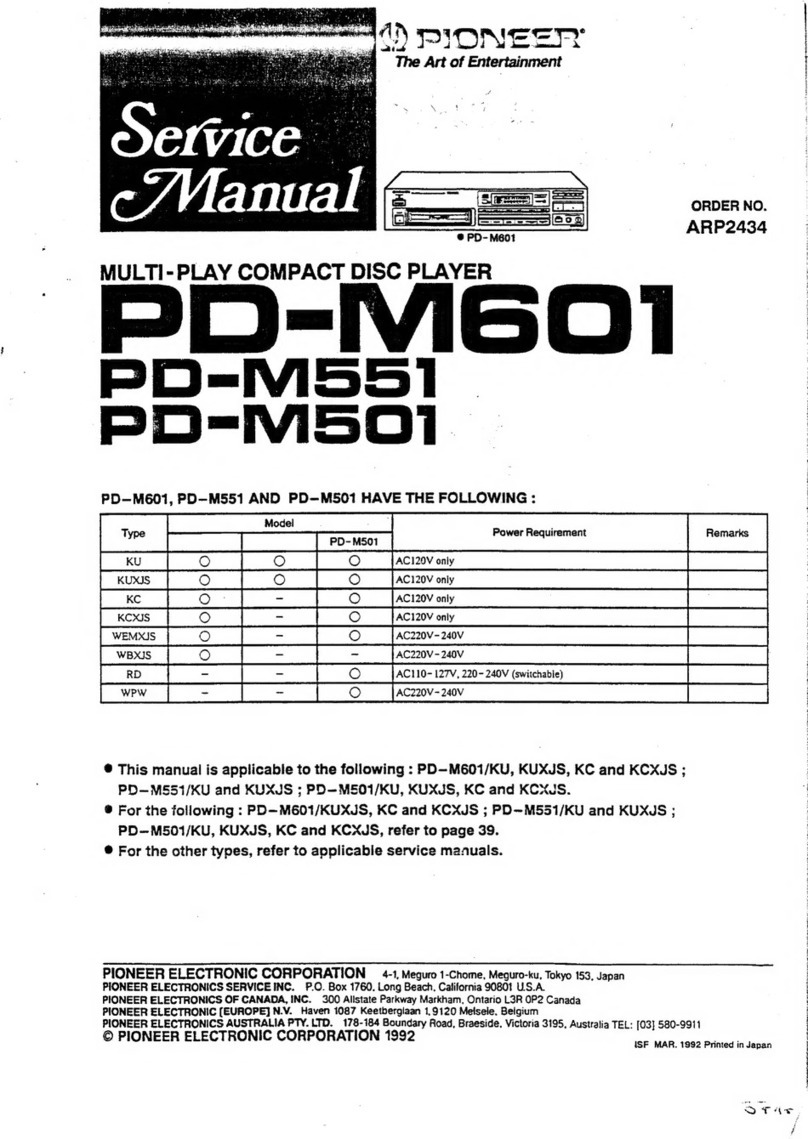
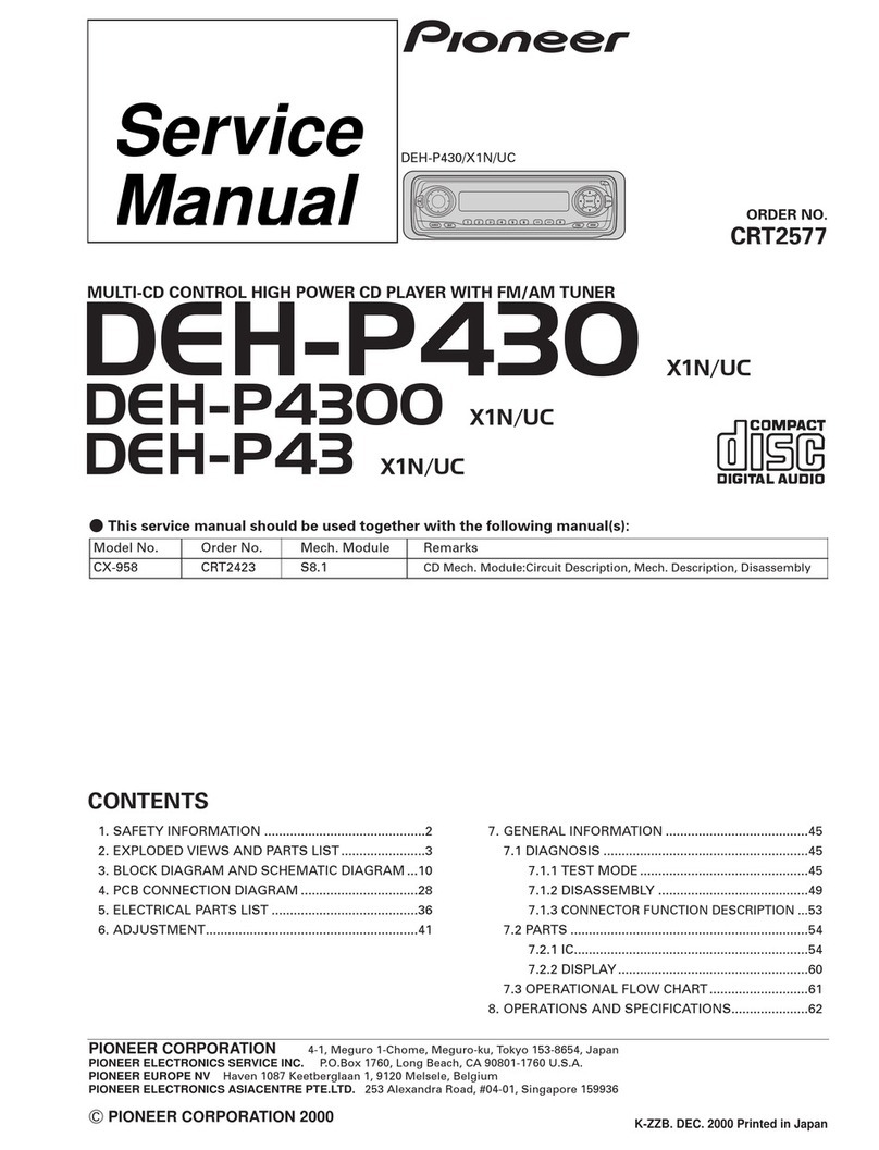
  9. Pioneer PD-M423 User manual

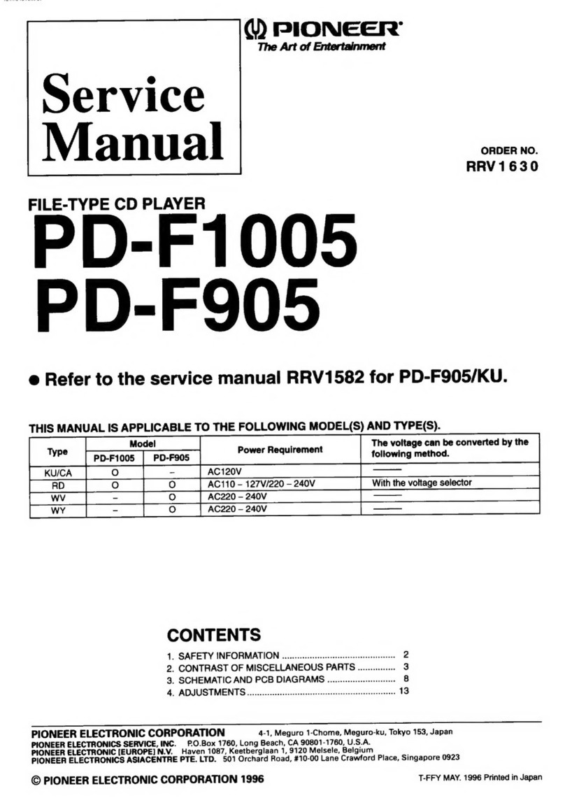
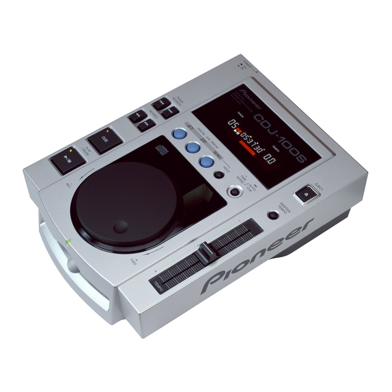
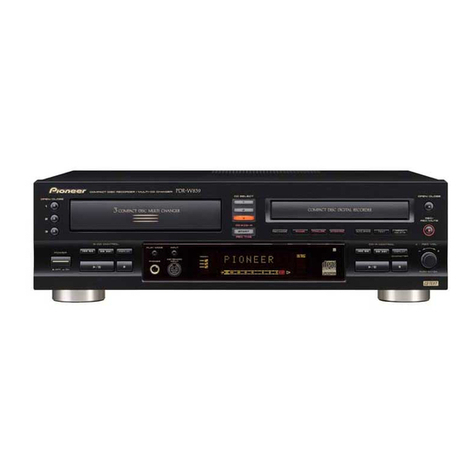
Pioneer PD-M423 User manual

d)
PIONEER’
The
Art
of
Entertainment
Service
anual
MULTI-PLAY
COMPACT
DISC
PLAYER
PD-M423
PD-M403
THIS
MANUAL
IS
APPLICABLE
TO
THE
FOLLOWING
MODEL(S)
AND
TYPE(S).
Type
Power
Requirement
ORDER
NO.
RRV1062
CONTENTS
1.
SAFETY
INFORMATION
-oescccsssccceeeeseeseetsseeeeeeees
2
2.
PACKING
AND
PARTS
LIST
-ecccccrcessereeeeeeetrereeees
3
3.
EXPLODED
VIEWS
AND
PARTS
LIST
----------+--++--
4
4.
BLOCK
DIAGRAM
ceccecceeecececetseessttaeeceeeneeeseneens
10
5.
SCHEMATIC
DIAGRAMGccrsrccereessesrrreeceeeeeeeeesenes
1
6.
PCB
CONNECTION
DIAGRAM
-:+-sseseceececeeeeeeeeees
17
7.
PCBPARTS
LIST
--:::s::ccccccccceteeeeeeeeeeseesseeseeeeees
23
8.
ADJUSTMENTS
cvrvcrsccercrsesteeccsecttennseteeeeeeesoesens
25
9.
IC
INFORMATION
eee
ee
eee
eee
rere
rere
ree
ee
eee
rere
34
10.
FL
INFORMATION
«++:-::seseeeeessereeeeeeeessssseessnenees
39
11,
FOR
PD-M423/KCXJ,
PD-M403/KUXJ
AND
KOXJ
stcccsessscceceeeeteceeseetsensessssnerseeeeeeereenens
40
12.
PANEL
FACILITIES
+--:::::::sssccesececesessesssnseeenseeees
a4
13.
SPECIFICATIONS
r--:eeeeeeeeseeeeeeeeeeeessnseseeneeeeees
42
PIONEER
ELECTRONIC
CORPORATION
4-1,
Meguro
1-Chome,
Meguro-ku,
Tokyo
153,
Japan
PIONEER
ELECTRONICS
SERVICE
INC.
P.O.
Box
1760,
Long
Beach,
California
90801
U.S.A.
PIONEER
ELECTRONICS
OF
CANADA,
INC.
300
Allstate
Parkway
Markham,
Ontario
L3R
OP2
Canada
PIONEER
ELECTRONIC
[EUROPE]
N.V.
Haven
1087
Keetberglaan
1,
9120
Melsele,
Belgium
PIONEER
ELECTRONICS
AUSTRALIA
PTY.
LTD.
178-184
Boundary
Road,
Braeside,
Victoria
3195,
Australia
TEL:
[03]
580-9911
©
PIONEER
ELECTRONIC
CORPORATION
1994
T
-
SSF
FEB.
1994
Printed
in
Japan®
PD-M423,
PD-M403
1.
SAFETY
INFORMATION
This
service
manual
is
intended
for
qualified
service
technicians;
it
is
not
meant
for
the
casual
do-it-yourselfer.
Qualified
technicians
have
the
necessary
test
equipment
and
tools,
and
have
been
trained
to
properly
and
safely
repair
complex
products
such
as
those
covered
by
this
manual.
Improperly
performed
repairs
can
adversely
affect
the
safety
and
reliability
of
the
product
and
may
void
the
warranty.
If
you
are
not
qualified
to
perform
the
repair
of
this
product
properly
and
safely,
you
should
not
risk
trying
to
do
so
and
refer
the
repair
to
a
qualified
service
technician.
WARNING
Lead
in
solder
used
in
this
product
is
listed
by
the
California
Health
and
Welfare
agency
as
a
known
reproductive
toxicant
which
may
cause
birth
defects
or
other
reproductive
harm
(California
Health
&
Safety
Code,
Section
25249.5).
When
servicing
or
handling
circuit
boards
and
other
components
which
contain
lead
in
solder,
avoid
unprotected
skin
contact
with
the
solder.
Also,
when
soldering
do
not
inhale
any
smoke
or
fumes
produced.
NOTICE
(FOR
CANADIAN
MODEL
ONLY)
Fuse
symbols
-§&—1
(fast
operating
fuse)
and/or
-§——
(slow
operating
fuse)
on
PCB
indicate
that
replacement
parts
must
be
of
identical
designation.
REMARQUE
(POUR
MODELE
CANADIEN
SEULEMENT)
Les
symboles
de
fusible
-§—H
(fusible
de
type
rapide)
et/ou
-§£—
(fusible
de
type
lent)
sur
CCI
indiquent
que
les
piéces
de
remplacement
doivent
avoir
la
méme
désignation.
(FOR
USA
MODEL
ONLY)
1.
SAFETY
PRECAUTIONS
The
following
check
should
be
performed
for
the
continued
protection
of
the
customer
and
service
technician.
LEAKAGE
CURRENT
CHECK
Measure
leakage
current
to
a
known
earth
ground
(water
pipe,
conduit,
etc.)
by
connecting
a
leakage
ANY
MEASUREMENTS
NOT
WITHIN
THE
LIMITS
OUTLINED
ABOVE
ARE
INDICATIVE
OF
A
PO-
TENTIAL
SHOCK
HAZARD
AND
MUST
BE
COR-
RECTED
BEFORE
RETURNING
THE
APPLIANCE
TO
THE
CUSTOMER.
2.PRODUCT
SAFETY
NOTICE
current
tester
such
as
Simpson
Model
229-2
or
equivalent
between
the
earth
ground
and
all
exposed
metal
parts
of
the
appliance
(input/output
terminals,
screwheads,
metal
overlays,
contro!
shaft,
etc.).
Plug
the
AC
line
cord
of
the
appliance
directly
into
a
120V
AC
60Hz
outlet
and
turn
the
AC
power
switch
on.
Any
current
measured
must
not
exceed
0.5mA.
Reading
should
Leakage
|
Ot
be
above
current
|
0.5mA
tester
Sd
Test
all
exposed
metal
surfaces
Also
test
with
plug
reversed
(Using
AC
adapter
plug
as
required)
Earth
ground
AC
Leakage
Test
Many
electrical
and
mechanical
parts
in
the
appli-
ance
have
special
safety
related
characteristics.
These
are
often
not
evident
from
visual
inspection
nor
the
protection
afforded
by
them
necessarily
can
be
ob-
tained
by
using
replacement
components
rated
for
vol-
tage,
wattage,
etc.
Replacement
parts
which
have
these
special
safety
characteristics
are
identified
in
this
Service
Manual.
Electrical
components
having
such
features
are
identified
by
marking
with
a
A
on
the
schematics
and
on
the
parts
list
in
this
Service
Manual.
The
use
of
a
substitute
replacement
component
which
dose
not
have
the
same
safety
characteristics
as
the
PIONEER
recommended
replacement
one,
shown
in
the
parts
list
in
this
Service
Manual,
may
create
shock,
fire,
or
other
hazards.
Product
Safety
is
continuously
under
review
and
new
instructions
are
issued
from
time
to
time.
For
the
latest
information,
always
consult
the
current
PItONEER
Service
Manual.
A
subscription
to,
or
ad-
ditional
copies
of,
PIONEER
Service
Manuai
may
be
obtained
at
a
nominal
charge
from
PIONEER.
PD-M423,
PD-M403
2.
PACKING
AND
PARTS
LIST
NOTES:
e
Parts
marked
by
“NSP”
are
generally
unavailable
because
they
are
not
in
our
Master
Spare
Parts
List.
e
The
A\
mark
found
on
some
component
parts
indicates
the
importance
of
the
safety
factor
of
the
part.
Therefore,
when
replacing,
be
sure
to
use
parts
of
identical
designation.
Parts
marked
by
“@”
are
not
always
kept
in
stock.
Their
delivery
time
may
be
longer
than
usual
or
they
may
be
unavailable.
Parts
List
Mark
No.
Description
Part
No.
Mark
No.
Description
Part
No.
1
Connection
Cord
with
PDE
—
319
9
CD
Packing
Case
PHG1999
Mini
Plug
(for
SR
cord)
10
Mirror
Mat
Sheet
Z23
—
007
2
Connection
Cord
with
PDE1109
Pin
Plug
(for
Audio)
NSP
101.
Dry
Cell
Battery
VEM
—
022
3
Remote
Control
Unit
PWW1089
(RO3,
AAA)
4
Battery
Cover
PZN1010
5
Magazine
Assy
PXA1523
6
Operating
Instructions
PRB1205
(English)
7
Styrol
Protector
(F)
PHA1276
8
Styrol
Protector
(R)
PHA1277
2
PD-M423,
PD-M403
3.
EXPLODED
VIEWS
AND
PARTS
LIST
NOTES:
e
Parts
marked
by
“NSP”
are
generally
unavailable
because
they
are
not
in
our
Master
Spare
Parts
List.
¢
The
A\
mark
found
on
some
component
parts
indicates
the
importance
of
the
safety
factor
of
the
part.
Therefore,
when
replacing,
be
sure
to
use
parts
of
identical
designation.
Parts
marked
by
“©”
are
not
always
kept
in
stock.
Their
delivery
time
may
be
longer
than
usual
or
they
may
be
unavailable.
3.1
EXTERIOR
Parts
List
Mark
No.
Description
A
Strain
Relief
2
32P
F.F.C/30V
A
3
Power
Transformer
A
4
Power
Cord
with
Plug
5
Bonnet
6
Foot
Assy
7
Screw
8
Rubber
Sheet
9
Function
Panel
10
Play
Button
11
Name
Plate
12
Power
Button
13
65
Label
14
Track
Button
15
Display
Window
16
Spring
(Door)
17
Earth
Lead
Unit
18
Door
19
Function
Board
Assy
A
20
Mother
Board
Assy
21
Screw
22
Screw
23
«Screw
24
Screw
25
earees
96)
osevade
27
Screw
28
Screw
Part
No.
CM
—
22C
PDD1041
PTT1237
PDG1015
PYY1149
AEC1531
IBZ30PO080FCC
AEBI111
PNW2387
PAC1766
PAM1608
PAC1719
ORW
1069
PAC1765
PAM1635
PBH1022
XDF
—
502
PNW2264
PWZ2769
PWM1858
BBZ30P060F
MC
BBZ30P080FZK
PPZ30P120FMC
FBT40P080FZK
IBZ30P180FMC
PDZ30P050F
MC
Mark
No.
NSP
101
NSP
102
NSP
103
NSP
104
NSP
105
NSP
106
Description
Part
No.
PCB
Mould
AMR1525
Under
Base
PNA1751
Rear
Base
PNA2068
Multi
Mechanism
Assy
PXA1532
Flat
Cable
(6P)
D20PY
YO615E
Switch
Board
Assy
PWZ2804
PD-M423,
PD-M403
Exterior
NOTE:
Screws
adjacent
to
V
mark
on
the
product
are
used
for
disassembly.
Multi
Mechanism
Assy
(=
See
section
3.2)
PD-M423,
PD-M403
|
°
°
‘
:
: °
3.2
MULTI
MECHANISM
ASSY
2
*1:
Fix
the
motor
101
on
the
loading
board
assembly
105
so
that
the
label
attached
on
the
motor
faces
the
direction
illustrated.
_~°
2
*1
Label
A
=
*2:
Fix
the
motor
101
on
the
motor
board
10
assembly
110
so
that
the
label
attached
on
the
motor
faces
the
direction
illustrated.
B
=
C
=
©
How
to
install
the
disc
table
(0)
Usenippers
or
other
tool
tocut
the
three
sections
marked
®
and
the
three
sections
marked
®
in
figure.
Then
remove
the
spacer.
[2]
While
supporting
the
spindle
motor
shaft
with
the
stopper,
put
spacer
on
top
of
yoke
M,
and
stick
the
disc
table
on
top
(takes
about
9kg
press-
ure).
Detach
the
spacer.
D
PD-M423,
PD-M403
Parts
List
Mark
No.
Description
Part
No.
Mark
No.
Description
Part
No.
1
Motor
Pulley
PNW
1634
49
Guide
Bar
PLA1094
2
Gear
Holder
PNW1929
50
__
Disc
Table
PNW
1067
3
PU
Frexible
Cable
PNP1343
51
Gearl
PNW2052
4
Cam
Gear
PNW1923
52
Gear2
PNW2053
5
Belt
PEB1138
53
Gear3
PNW2054
6
Top
Guide
N
PNW
2441
54
Pinion
Gear
PNW2055
7
~~
Gear
Pulley
PNW1918
55
PWB
Holder
PNW2057
8
GearS
PNW1919
56
Carriage
Base
PNW2445
9
GearL
PNW1920
57
D.C.
Motor
Assy
PEA1235
10
Eject
Spring
PBH1107
(spindle
with
oil)
11
Switch
Lever
PNW1927
58
Pickup
Assy
PEA1291
12
Seven
Bar
PNW1931
59
Disc
Table
Assy
PEA1035
13.
Sub
Rotary
Lever
PNW
1933
60
Screw
BBZ26P060FMC
14
Sub
Rotary
Lever
Spring
PBH1111
61
Screw
BPZ20PO60FMC
15
Rotary
Lever
PNW1932
62
Screw
BPZ26P100FMC
16
Drive
Plate
PNW1930
63
Screw
JFZ17P025FZK
17.
Motor
Screw
PBA-
112
64
Screw
JFZ20P040FMC
18
Holder
Lever
Spring
PBH1110
65
Washer
WT12D032D025
19
Disc
Holder
PNW1924
66
Connector
Assy
PDE1241
20
Cushion
A
PED1001
67
Stopper
Spring
PBH1131
21
~Holder
Lever
PNW1925
68
Stopper
PNW2069
22
Float
Rubber
PEB1014
69
D.C.
Motor
Assy
PEA1246
23
+
Float
Rubber
PEB1132
(CARRIAGE)
24
~~
‘Float
Screw
PBA1073
70
Upper
Chassis
PNB1267
25
Release
Lever
PNW1934
71
Sub
Chassis
PNW2440
72
Connector
Assy
PDE1240
26
Release
Spring
PBH1106
27.
~=Clamper
Cam
PNW1922
28
Clamper
Holder
PNW1921
29
~Clamper
Spring
PBH1109
30
Clamper
PNW1857
NSP
101
Motor
VXM1033
31
Lock
Lever
PNW1917
NSP
102
Eject
Lever
PNB1306
32
Lock
Spring
PBH1108
103
eee
33
Stair
NL
PNW2443
NSP
104
Servomechanism
Assy
M
PXA1512
34
Stair
NR
PNW2444
35
Synchronize
Lever
PNW1926
NSP
105
Loading
Board
Assy
PWZ2038
106
eovovee
36
Motor
Assy
PEA1130
107
«eee8
(LOADING,
DISC
SELECT)
NSP
108
Main
Chassis
PNW2074
37.
Screw
PMZ26P040FMC
NSP
109
Select
Board
Assy
PWZ2533
38
Screw
PPZ30PO080FMC
39
Screw
BBZ30P060FMC
NSP
110
Motor
Board
Assy
PWZ2040
NSP
111
Mechanism
Board
Assy
PWX1192
40
Washer
WT26D047D025
NSP
112
Earth
Lead
Unit
PDF1074
41
Washer
WA31D054D025
NSP
113
Clamp
Magnet
PMF1014
42
ERing
Z39-010
NSP
114
Gear
Stopper
PNB1303
43
Screw
IPZ30PO80FMC
NSP
1t1S
YokeM
PNB1312
44
Rubber
Spacer
PEB1238
NSP
116
AVAngle
PNB1405
45
Rubber
Spacer
PEB1179
NSP
117
Carriage
DC
Motor/0.3W
PXMI1027
46
Silent
Ring
PBK1093
47
Washer
WA62D130D025
48
Earth
Spring
PBH1132
PD-M423,
PD-M403
BLOCK
DIAGRAM
4.
TVNOIS
Olagnv
©
AlddNS
YW3IMOd
ae
Aaya
NOILONNSA
AV1dSIG
(SOP!)
dd
(LOvd!)
ova
o18
Bulpeo
ls
ebersed.
(1g€9!)
eeu
Ndod
Buryoess
-
SNO0O4-
A\quessy
dNAIId
(10€91)
(1Ston
yW3q00930
10
5.
SCHEMATIC
DIAGRAM
5.1
Waveforms
*1
SOT-
JUMP:After
switching
to
the
pause
mode,
press
the
Note:
The
encircled
numbers
denote
measuring
points
in
the
schematic
diagram.
TP1-
Pin
1:PLAY
MODE
(2)
(RF)
500mVidiv
SO0Onsec/div
TP1-
Pin
1:
TRACK
SEARCH
MODE
(RF)
500mV/div
200
yu
sec/div
2.600028
88)
TP1-
Pin
6:PLAY
MODE
(3)
(FOER)
100mV/div
1Omsec/div
TP1-Pin
2:PLAY
MODE
(TRER)
WVidiv
10msec/div
TP1-
Pin
2:50T-
JUMP
(*1)
MODE
(TRER)
1Vidiv
1msec/div
manual
search
key.
*2
FOCUS
-
IN:Press
the
key
without
loading
a
disc.
IC202-
Pin
3
:FOCUS
-
IN
(*2)
MODE
(FODR)
1Vidiv
200msec/div
IC202-
Pin
3
:PLAY
MODE
(FODR)
1Vidiv
1msec/div
IC202-
Pin
4:PLAY
MODE
6)
(TRDR)
500mVidiv
1msec/div
1C202-
Pin
4:50T
-
JUMP
(*1)
MODE
(TRDR)
500mVidiv
1msec/div
IC201-
Pin
9:PLAY
MODE
7)
(SPDR)
1Vidiv
50Omsec/div
IC201
-
Pin
8:
TRACK
SEARCH
MODE
(SPDR)
2Vidiv
50msec/div
IC202-
Ping
:PLAY
MODE
(CADR)
0.5Vidiv
2sec/div
1C202-
Ping
:
TRACK
SEARCH
MODE
(CADR)
2V/div
200msec/div
1C151-Pin
32:PLAY
MODE
(EFM)
2Vidiv
500nsec/div
1C401-Pin
7
:PLAY
MODE
(1kHz)
(LO
)
(D/A
DATA
OUT)
1V/div
200
psec/div
1C401-Pin
8
:PLAY
MODE
(1kHz)
(1)
(LO
)
(D/A
DATA
OUT)
div
200
i
1V
sec/div
1C301-Pin
22
:PLAY
MODE
(1kHz)
(BCLK)
2V/div
500nsec/div
(aa
al ol
eel
cael
a
coe
el
oo
ey
1C301-Pin
20
:PLAY
MODE
(1kHz)
(LRCK)
2Vidiv
10
usec/div
1C301-Pin
21
:-PLAY
MODE
(1kHz)
(PCMD)
2V/idiv
5O0Onsec/div
Pin-
OUTPUT:PLAY
MODE(1kHz)
1Vidiv
200
usec/div
STRACK
SEARCH
MODE
Upper:
TP1-
Pin
1
(RF)
1V/div
Lower:
IC
151-
Pin
29
(MIRR)
2Vidiv
200
usec/div
eee
tee
eee
t
:PLAY
MODE
Upper:
TP1-
Pin
1
(RF)
1V/div
Lower:
1C151-
Pin
30
(DFCT)
SVidiv
200
usec/div
1C301-Pin
3
:PLAY
MODE
3)
(MDP)
2Vidiv
2
usec/div
(Upper)
—
GND
~—
GND
(Lower)
!1C301-Pin
9
;:PLAY
MODE
(PCO)
2Vidiv
10
usec/div
NOTE
FOR
SCHEMATIC
DIAGRAMS
(Type
4A)
1.
When
ordering
service
parts,
be
sure
to
refer
to
“PARTS
LIST
of
EXPLODED
VIEWS”
or
“PCB
PARTS
LIST”.
.
Since
these
are
basic
circuits,
some
parts
of
them
or
the
values
of
some
components
may
be
changed
for
improve-
ment.
.
RESISTORS:
Unit:
k:kQ,
M:MQ,
or
9
unless
otherwise
noted.
Rated
power:
1/4W,
1/6W,
1/8W,
1/10W
unless
otherwise
noted.
Tolerance:
(F):
+1%,
(G):
+2%,
(K):
+10%,
(M):
+20%
or
+5%
un-
less
otherwise
noted.
.
CAPACITORS:
Unit:
p:pF
or
wF
unless
otherwise
noted.
Ratings:
capacitor
(uF)/
voltage
(V)
unless
otherwise
noted.
Rated
voltage:
50V
except
for
electrolytic
capacitors.
.
COILS:
Unit:
m:mH
or
wH
unless
otherwise
noted.
.
VOLTAGE
AND
CURRENT:
LoJor-v:
DC
voitage
(V)
in
PLAY
mode
unless
otherwise
noted.
©
mA
or+
mA:
DC
current
in
PLAY
mode
unless
otherwise
noted.
Value
in(
)
is
DC
current
in
STOP
mode.
OTHERS:
©
@or®@
:
Adjusting
point.
©
<<]:
Measurement
point.
©
The
A
mark
found
on
some
component
parts
indicates
the
im-
portance
of
the
safety
factor
of
the
parts.
Therefore,
when
re-
placing,
be
sure
to
use
parts
of
identical
designation.
-
SCH—O
ON
THE
SCHEMATIC
DIAGRAM:
e
SCH—D
indicates
the
drawing
number
of
the
schematic
dia-
gram.
(SCH
stands
for
schematic
diagram.)
-
SWITCHES
(Underline
indicates
switch
position):
FUNCTION
BOARD
ASSY
S701:
EJECT
S702
:
REPEAT
S703.
:
PROGRAM
S704:
DISC
S705:
kKKI-
<j
S706:
b>
-
Dot
S707
:
STOP
s7os
:
>/(0
S709
:
RANDOM
S710
:
HI-LITE
SCAN
SWITCH
BOARD
ASSY
S80t
:
POWER
PD-M423,
PD-M403
13
PD-M423,
PD-M403
ese.
MEI
SOSER
Y
ae
ee
ee
|
ef
B
4
7
(\)
R
4
OOSOOVOOOOS
acT
T-
Act
T+
Leno
|e/cno
+
a
<
FFFPETRREEE
Sips
PAG
AB
ine
8
he
AA
eT
SE
Ot
i
—
|
SERVO
MECHANISM
ASSY
Al
Dee
_
7
7
S
1)
TpecKup
ASSY
|
(PEA1291)
'
i
|
i}
H
ry
|
|
{ouf
|e
ml
xian
|
|
|
{
ital
{
|
|
ee
ot
|
|
:
i
biog
i
|
|
bday
i|
||
rey
|
|
|
|
él
!
|
|
pate
|
|
|
!
|
HOLOGRAM
LASER
UNIT
:
B
]
Eressens
|
rhe
|
tS
ght
Sp
og
at
-4
ee
|
|
PRE
AMP
BOARD
ASSY
1
be
2
ia
if
i
=
fe
ee
apes
z
=
[
peer
ae
(23
we
=a
14
la
Ves
|
|
|
1
CN134
7
12FMZ—ABT
Be
Ce
ee
tt
ean
of
ae
ma
a
|
at
Ale
I
|
!
INSIDE
SW
osce16
‘|
|
!
2!
D.C.
MOTOR
ASSY
joN202
|
':
(SPINDLE)
VKN1
051
|
<|
S}INSo
i2|
'
seo
fn
is:
ete
saree
a
CADR
2
i=
;
2
ii
2
(6:
|
|
<
“Lis
|D.C,
MOTOR
assy
:
eae
=
iS
(iw
es
ey
R550
z
gear
a
sigs
Lr
‘
ne
ope
$601
—~
44)
G)
x
LPSt
.
ie
Se
Ss
LPs2
(Mz
G) 3)
pI
LOAD
=
|
1130
o_o
La
|
censor
i
es
|
4
{LOADING}
4-173979-4|
2
|
CN203
3-173981-4
l
;
LOADING
BOARD
L
assy
(pwzz038)
|i
|
\
|
|
\
{
|
I
|
|
i
|
|
{
|
!
Ves
|
R3G2~R365
]
+OK
|
|
Beasees
[
S603:PSG1010-
A
Be
s2131-0610]|
@
=
2
sse3
(7)
G)
acNce2l
(i)
MZS1
|
be il
b>
[Ab
=<
Pl
=<
GP
2-2)
(2)
(2)
fee
ro
HR
eT
ces
Sr
|
Se
;8604-se06:psciaie
7)
aan
|
SELECT
\
DISC
SELEC
(©
Y
:
1
lll
kpwz2s33)
|
7
|
|
MOTOR
BOARD
ASSY!
eee
1$214
7-061
(PWZ2040)
eee
L
=
R210
47
1¢202
(273)
LAbS2B
47
C285
B
@1
R205
R219
1€201
(373)
47?
LAE520
(SPINDLE
DRIVE)
R244
22K
1.7
1.7
R243
16202
(173)
LA652@
R20
(FOCUS
DRIVE)
fea
»
LA6S20
R221
oO
R222
gee
LOUT
1€201
(2/3)
190K
LAG528
{LOADING
DRIVE)
1C201
a73)"
LA6S20
R224
18@K
R226
1
Q@OK
R227
10@K
R229
(DISC
SELECT)
180K
-35
v-8
OO58OO
RKP—-S33q
wWOooo
TRZ
se
N
m
ele
|
|
€|
§
TR.GAIN
Se
CXA13720
Ves
R360
18K
(SERVO
CONTROL)
[C202
(3/3)
(CARRIAGE
DRIVE)
120K
0
OOK
go
LIN
TGS
TSTISSSOOOSSSOS
©
2
®
©
>
O
¢
9
¢
®
¢
®
¢
DOE
>
®
Ick.
®
¢
©
I:
B96
TIOITOSO
OOOO
OOOSOSO
SOOO
SH
SOSSSOS
SWITCH
BOARD
0701-07835
1SS133xX
X35
S701~S710
PSGIOBE
X18
|
ASSY
S709
1(PWZ2804)
are
!
$3801
PSG12@6
MS
POWER,
l
[eT
|
|
I
|
Ge
ee ee
a
tar]
87a
mer
sro
aa
jPPEEEEUCEEEMEEEEEELEELEE
{Laal
eieal
FLUORESCENT
DISPLAY
VSS1028
R356
STBL
Heedeeeeee
5
e
o
3N0,
REMOTE
SENSOR
S8X1
785-51
PD-M4
23
ONLY
FUNCTION
BOARD
ASSY
(PWZ2768
:
PD-M403)
(PWZ2769
:
PD-M423)
eee
ee
ee
ee
ee
SUB
BOARD
ASSY
(PWX1
334
:
PD-M403)
(PWX1336
:
PD-M423)
A,
MOTHER
BOARD
ASSY
(PWM1856
-
PD-M403)
(PWM1858
-
PD-M423)
V45
R355
10K
Ves
he
2
thes
PD4520A
an
(SYSTEM
CONTROL)
oS
2
¢
STBL
14
in
ae
,
0352
MTZJS
1
VD5
———_—_——————————____,
{
63
-89ma
(39
mA)
R22
-4.5
Q4a1
2a
28K
246
R430
R438
cai?
}.
2K
33K
24
C436
vos
39P
cH
a
G9)
O
cab
-
©
ar.
PMac416
a”
|
8S
WO
to
;+
|
G
rar
Pes
9
On
Ba
cat
5
C435
=
RO
oo
39P
2
P|
V0S
=z
C413
@1
v+B
R499
3K
Q4e5
OTC1I24ES
1
C425
-9.5
7
102@P
Q405:
MUTE
ORIVER
VveR
0335
188254
L391
19h
R392
1K
0394
C321
1$S254
=
ee
0392
1SS254
IC24:
SYSTEM
RESET
AND
+5V
REGULATOR
oe
10405
(272)
NUM@5580—-0
C405.
LOW-PASS
FILTER
R439
47K
C437
39P
S|
a
10485
(172)
NIM4558D-O
7502144S
-9-5
Q403
25021445
=
C441
M
otal
ie)
7a
K
XA
13720
Voltage Voltage Voltage
Voltage
(v)
(v)
(Vv)
v)
pi
2s
fist
25
[a]
so
[a
|
20
|
2
[25
|
ia
[estos
|
26
|
01
|
a3
[2.70028
|
Piz
{
25
[24
[asoso[
3
[
50
[4a
[
24
|
YA392
gy
RKN1004
|
SR
JACK
(CONTROL)
JAS91
tN
RKN1
O04
A
KUKJ:
PDGIO1S.
A
KCXJ
ROG
1010
AC
POWER
CORD
AC1IZ0V/
6OHz
10K
1€21
130mA
paesrri2
A
(76ma)
TIES?
VIESZ
Cig
g
2
o1
KH
C27.
C17
335/16
@.@1
HH
wo
wr
ps4
Ny
cis
MTzJie8
eal
e.01
Lal
82—110ma
(26ma)
C52
cis
J08735
@.01
Pee
ei
4
Daz
R52
RS1
A
1182
1.5K
19K
ci
Ba.
POWER
TRANSFORMER
re
LIVE
NEUTRAL
a)
A
Rxc-061
CN351
HLEM3@S—1
HLEM32S—1
CN7B1
HLEM36R—1
HLEMS2R—-1
PDD1843
bLbbEGS
:
FOCUS
SERVO
LOOP
LINE
>;
TRACKING
SERVO
LOOP
LINE
:
SIGNAL
ROUTE
:
LOADING
MOTER
ROUTE
:
SPINDLE
MOTER
ROUTE
:
CARRIAGE
MOTER
ROUTE
.
DISC
SELECT
MOTER
ROUTE
JA481
(172)
PKB1Q0@09
L
INEOQUT
©}
JA4@01
(272)
PKB10@3
__|
1
I
va
1
3
|
4
|
ee
=
a
=
—_
‘6
|
a
7
6.
PCB
CONNECTION
DIAGRAM
A)
s)
=
iS
w
MOTHER
BOARD
ASSY
e
This
diagram
Is
viewed
from
the
mounted
parts
side.
LOADING
BOARD
ASSY
A
AC
POWER
CORD
AC
120V
60Hz
SHaMaRY
:
SELECT
BOARD
ASSY
a
8
©
NOTE
FOR
PCB
DIAGRAMS:
Ve
siesh
Lea
in
PCB
diagrams
match
those
in
the
schematic
“
2.A
onncaicon
between
the
main
parts
of
PCB
and
schematic
<
Q405
diagrams
is
shown
below.
=
=
:
es
oe
lela
oe
BCE
BC
EB
CE
Transistor
7
ve
lg
lal
“
pDGsodDeas
ee
FAO
:
Field
effect
2
\s
E
Ic21
(
UU
Pes
‘
as
WEL
|--
ie)
de
401
Hil
A
eat
x
mL
|
foam
ee
a
hapa
IBA
le
!
They)
Sieve
Q301
hess
P
x
BRN
oo
T
ou
ey
s
C
TO
PICKUP
ASSY
re
TAN
o>.
adi
i
CN102
ee
bi.
i
ic154
1¢301
di
S
,
Hee
8
ON
:
SWITCH
BOARD
ASSY
FUNCTION
BOARD
ASSY
|
|
Rot
+
.
ercue
he
4
ca
oP
Ze:
GA
|
°°
———————
Y
pe
Ic
354
\S
a
en
D
Oo
I
TS
r
SSSSS[S-JSSL
;
vb
eo-
(eae
te
|
yy)
tne
SU
[ie
y=
©
sO
>
une
ZY
fs
We
Wie
TL
Comings
(einen:
bh
mye
OEY
PNP1366-A
|
A
| |
‘
|
4
|
|
S
|
7
|
8
|
9
PNP1365-A
E0AM-G4
.€SAM-G4
8
N
a
|
@
[
h
|
E
I
Ss
|
r
MAADAIC
UOITOSAUNOD
99
.d
Ye2eA
QAAOS
AAHTOM
anes
BaWOSIOA
A
YeeA
AAAOd
DUIGAO]
This
diagram
Is
viewed
from
the
foil
side.
sHOS
VOSt
JA
°
YAAMIAS
A
YeeA
GAAOS
T9552
»)
B
8
8
rsol
—
S@tAV
|10891
toro
sosol
A-tEEtAN4
toE0
9
Ye2A
FXII
OT
SOrUS
roED|
terol
YeeA
GAHAOS
UOITOUVUA
YeeA
GAAOE
HOTIWe
=
ata.
DP»
4
e
ae
(Cr
AAAAAAAAAAAS
‘
=i
reel
\X
:
tosol
-28
ENS
E—$—$———SSSSSSSSAS_F¥5
A-caeEtaug
A-
BdEtqn9
20
~]
2
|
2
|
x
i
2
i
$
|
&
|
&
|
=
|
.
PD-M423,
PD-M403
7.
PCB
PARTS
LIST
NOTES:
e
Parts
marked
by
“NSP”
are
generally
unavailable
because
they
are
not
in
our
Master
Spare
Parts
List.
e
The
A\
mark
found
on
some
component
parts
indicates
the
importance
of
the
safety
factor
of
the
part.
Therefore,
when
replacing,
be
sure
to
use
parts
of
identical
designation.
e
Parts
marked
by
“@”
are
not
always
kept
in
stock.
Their
delivery
time
may
be
longer
than
usual
or
they
may
be
unavailable.
©
When
ordering
resistors,
first
convert
resistance
values
into
code
form
as
shown
in
the
following
examples.
Ex.1
When
there
are
2
effective
digits
(any
digit
apart
from
0),
such
as
560
ohm
and
47k
ohm
(tolerance
is
shown
by
J=5%,
and
K=10%).
560
Q
>
S56X
LO
PSG]
corre
reece
cere
rte
cere
ee
neeeee
RD1/8PM[5][6]{1]J
Vy)
0
ne
oa
ee
ok
ee
RD1/4PS
[4][7][3]J
0.5
ORS
ceccrcccccecc
eee
e
sence
neces
eeeeeteeeeeceees
RN2H
[O}[RI[S]K
1Q
ce]:
siete
aie
ea
elbS
as
ered
Slee
a
«Bee
seine
we
Meee
eraews
RS1P[0][1][0]K
Ex.2
When
there
are
3
effective
digits
(such
as
in
high
precision
metal
film
resistors).
562k
Q—>
562
X
LO
P5621]
cer
ccc
cece
eect
e
teen
eee
eeeeeee
RN1/4PC[5][6][2][1]F
Mark
No.
Description
—S-_——
PartNo.
Mark
No.
__Description
_—§-_——
PartNo.
LIST
OF
ASSEMBLIES
CAPACITORS
C11,
C13
CERAMIC
CAPACITOR
CKCYF103Z50
aA
MOTHER
BOARD
ASSY
PWM1858
C15
CERAMIC
CAPACITOR
CKCYF103Z50
C155
CERAMIC
CAPACITOR
CKCYB561K50
NSP
MECHANISM
BOARD
ASSY
PWX1279
C156
CERAMIC
CAPACITOR
CGCYX333K25
NSP
LOADING
BOARD
ASSY
P¥Z2038
C157
CERAMIC
CAPACITOR
CGCYX103K25
NSP
MOTOR
BOARD
ASSY
PWZ2040
NSP
SELECT
BOARD
ASSY
P¥Z2533
€158,C159
CERAMIC
CAPACITOR
CGCYX104K25
C16
CERAMIC
CAPACITOR
CKCYF103250
NSP SUB
BOARD
ASSY
PWX1336
C160
ELECT.
CAPACITOR
CEAS4R7M50
FUNCTION
BOARD
ASSY
PWZ2769
C161
CERAMIC
CAPACITOR
CGCYX104K25
NSP
SWITCH
BOARD
ASSY
PWZ2804
C162
ELECT.
CAPACITOR
CEAS4R7M50
NSP
MECHANISM
BOARD
ASSY
PWX1192
C163
CERAMIC
CAPACITOR
CGCYX104K25
C164
CERAMIC
CAPACITOR
CGCYX103K25
C167
CERAMIC
CAPACITOR
CKCYF103Z50
C168
CERAMIC
CAPACITOR
CGCYX333K25
MOTHER
BOARD
ASSY
C169
CERAMIC
CAPACITOR
CGCYX103K25
SEMICONDUCTORS
C17
CERAMIC
CAPACITOR
CKCYF103Z50
1C151
SERVO
IC
CXA1372Q
C170
CERAMIC
CAPACITOR
CKCYB332K50
A
1€201,
1C202
POWER
OP-AMP
IC
LAG520
C171
CERAMIC
CAPACITOR
CKCYB102K50
A
IC21
REGULATOR,
IC
PQOSRR12
C172
CERAMIC
CAPACITOR
CKCYB472K50
1C301
EFM
DEMODULATION
IC
CXD2517Q
C205,C210
CERAMIC
CAPACITOR
CKCYF103Z50
1C351
MICROCOMPUTER
IC
PD4520A
C215
CERAMIC
CAPACITOR
CKCYF103Z50
1C401
CONVERTER
IC
TC9268P
C218
CERAMIC
CAPACITOR
CGCYX103K25
1C405
OP-AMP
IC
NJM4558D-D
(219
CERAMIC
CAPACITOR
CKCYF103Z50
Q301
TRANSISTOR
2803732
C25
ELECT.
CAPACITOR
CEAS332M16
Q401
N-FET
2SK246
C26
ELECT.
CAPACITOR
CEAS331M16
Q403,Q404
TRANSISTOR
28D2144S
C27
ELECT.
CAPACITOR
CEAS330M16
Q405
TRANSISTOR
DTC124ES
C301
CERAMIC
CAPACITOR
OGCYX104K25
A
D11-D14
DIODE
11ES2
C306
CERAMIC
CAPACITOR
CKCYB152K50
D352
ZENER DIODE
MTZJ5.
1B
C307
CERAMIC
CAPACITOR
CGCYX473K25
D391-D394_
DIODE
18S254
C308
CERAMIC
CAPACITOR
CGCYX103K25
D401
DIODE
188254
C309
ELECT.
CAPACITOR
CEASR47M50
aA
D52
DIODE
L1ES2
C313
CERAMIC
CAPACITOR
CCCCH100D50
DS4
ZENNER
DIODE
M1ZJ18B
C315
CERAMIC
CAPACITOR
CKCYF103Z50
C321
CERAMIC
CAPACITOR
CCCSL10150
COILS
C351
ELECT.
CAPACITOR
CEAS471M6R3
L351
AXIAL
INDUCTOR
LAU100K
L391
AXIAL
INDUCTOR
LAUO10K
C353,
C361
CERAMIC
CAPACITOR
CKCYF
103250
C403,C404
CERAMIC
CAPACITOR
CCCCH150J50
C407
CERAMIC
CAPACITOR
CCCSL101J50
23
PD-M423,
PD-M403
Mark
No.
Description
Part
No.
C413-C416
AUDIO
FILM
CAPACITOR
CFTYA104J50
C417
CERAMIC
CAPACITOR
CKCYF103250
C425
CERAMIC
CAPACITOR
QCCSL101J50
C429,C430
CERAMIC
CAPACITOR
CCCCHS60J50
C433,C434
ELECT.
CAPACITOR
CEAS220025
C435-C438
CERAMIC
CAPACITOR
CCCCH390J50
C441,C442
FILM
CAPACITOR
PCL1030
(0.
0015/50¥)
C52
ELECT.
CAPACITOR
CEAS101M35
RESISTORS
VR151,
VRI52
VR(22K)
PCP1030
OTHER
RESISTORS
RD1/6PUO
D0
OTHERS
CN131
CONNECTOR
12FMZ-ABT
CN202
CONNECTOR
VKN1051
CN203
CONNECTOR
4P
4-173981-4
CN204
6P
JUMPER
CONNECTOR
52147-0610
CN351
CONNECTOR
32P
9604S-32C
JA391
JACK(FOR
CONTROL
IN)
RKN1004
JA392
JACK
(FOR
CONTROL
OUT)
RKN1004
JAAO1
JACK(FOR
LINE
OUT)
=
PKB1009
X351
CERAMIC
OSCILLATOR
_
¥SS1028
x401
CRYSTAL
OSCILLATOR
—
PSS1008
A
RAPPING
TERMINAL
RKC-061
LOADING
BOARD
ASSY
SWITCHES
$601,
S602
PUSH
SWITCH
DSG1016
OTHERS
CN601
CONNECTOR
4P
4-173979-4
MOTOR
BOARD
ASSY
OTHERS
CN602
6PJUMPER
CONNECTOR
52151-0610
SELECT
BOARD
ASSY
SWITCHES
$603
DETECTOR
SWITCH
PSG1010
$604~S606
PUSH
SWITCH
DSG1016
FUNCTION
BOARD
ASSY
SEMICONDUCTORS
D701-D703
DIODE
18S133X
SWITCHES
$701-S710
SWITCH
PSG1006
OTHERS
v701
FL
INDICATOR
TUBE
PEL1084
CN701
CONNECTOR
32P
9604S-32F
REMOTE
SENSOR
SBX1785
24
Mark
No.
Description
Part
No.
SWITCH
BOARD
ASSY
SWITCHES
S801
SWITCH
PSG1006
MECHANISM
BOARD
ASSY
OTHERS
(N610
CONNECTOR
4P
VKN1061
S610
PUSH
SWITCH
DSG1016
PD-M423,
PD-M403
8.
ADJUSTMENTS
8.1.
Adjustment
Methods
If
a
disc
player
is
adjusted
incorrectly
or
inadequately,
it
may
malfunction
or
not
work
at
all
even
though
there
is
nothing
at
all
wrong
with
the
pickup
or
the
circuitry.
Adjust
correctly
following
the
adjustment
procedure.
@
Adjustment
items/Verification
Items
and
Order
If
the
specified
values
cannot
be
obtained
or
no
adjustment
is
possible
by
performing
the
verifications
or
adjustments
described
in
steps
1
—
4,
the
pickup
block
may
be
defective.
[sep
[
mem
—~—~S—*dCSSCeat
Point
|__Adlutnant
Location
pe!)
Focus
offset
verification
TP1,
Pin6(FCS.
ERR)
oa
Tracking
error
balance
verification
TP1,
Pin2(TRK.
ERR)
Pickue
radial/tangential
direction
tilt
TP1,
Pin
1(RF)
Radial
as
adjustment
screw,
adjustment
Tangential
tilt
adjustment
screw
;
Pani
TP1,
Pin
S(FCS.
IN)
‘
Vv
:
8
|
Focus
servo
loop
gain
adjustment
TP1,
Pin
6(FCS.
ERR)
R152(FCS.
GAN)
:
da at
TP1,
Pin3(TRK.
IN)
Vv
:
ae
Tracking
servo
loop
gain
adjustment
TP1,
Pin2(TRK.
ERR)
R151
(TRK.
GAN)
@
Abbreviation
table
FCS.
ERR
_
:Focus
Error
TRK.
ERR
:Tracking
Error
FCS
GAN
_
:Focus
Gain
TRK
GAN:
Tracking
Gain
FCS.
IN
:Focus
In
TRK.IN
—:Tracking
In
@
Measuring
Instruments
and
Tools
1.
Dual
trace
oscilloscope
(10:1
probe)
2.
Low-frequency
oscillator
3.
Test
disc
(YEDS-
7)
4.
Low
pass
filter
(39k
Q
+0.001
u
F
)
5.
Resistor
(100
kQ
)
6.
Standard
tools
25
PD-M423,
PD-M403
@
Test
Point
and
Adjustment
Variable
Resistor
Positions
MOTHER
BOARD
ASSY
VR
151
TP!
TR.GA
(eo)
VR1521
CNI31
[
es
|
FO.GA](~__]
CN201
10151
<>
ae
Figure
1.
Adjustment
Locations
@
Notes
1.
Use
a
10:1
probe
for
the
oscilloscope.
2.
All
the
knob
positions
(settings)
for
the
oscilloscope
in
the
adjustment
procedures
are
for
when
a
10:1
probe
is
used.
@
Test
Mode
These
models
have
a
test
mode
so
that
the
adjustments
and
checks
required
for
service
can
be
carried
out
easily.
When
these
models
are
in
test
mode,
the
keys
on
the
front
panel
work
differently
from
normal.
Adjustments
and
checks
canbe
carried
out
by
operating
these
keys
with
the
correct
procedure.
For
these
models,
all
adjustments
are
carried
out
in
test
mode.
[Setting
these
models
to
test
mode]
How
to
set
this
model
into
test
mode.
1.
Unplug
the
power
cord
from
the
AC
socket.
2.
Short
the
test
mode
jumper
wires.
(See
Figure
1.)
3.
Plug
the
power
cord
back
into
the
AC
socket.
When
the
test
mode
is
set
correctly,
the
display
is
different
from
what
it
usually
is
when
the
power
is
turned
on.
If
the
display
is
still
the
same
as
usual,
test
mode
has
not
been
set
correctly,
so
repeat
Steps
1
—
3.
26
PD-M423,
PD-M403
(Release
from
test
mode]
Here
is
the
procedure
for
releasing
the
test
mode:
1.
Press
the
STOP
key
and
stop
all
operations.
2.
Unplug
the
power
cord
from
the
AC
socket.
[Operations
of
the
keys
in
test
mode]
|
Code
|
KeyName
|
Function
In
Test
Mode
Explanation
PGM
Focus
servo
close
The
laser
diode
is
lit
up
and
the
focus
actuator
is
lifted
(PROGRAM)
up,
then
lowered
slowly
and
the
focus
servo
is
closed
at
the
point
where
the
objective
lens
is
focused
on
the
disc.
With
the
player
in
this
state,
if
you
lightly
rotate
the
stopped
disc
by
hand,
you
can
hear
the
sound
the
focus
servo.
If
you
can
hear
this
sound,
the
focus
servo
is
operating
correctly.
If
you
press
this
key
with
no
disc
mounted,
the
laser
diode
lights
up,
the
focus
actuator
is
pulled
up,
then
the
actuator
is
lowered
and
raised
three
times
and
retuned
to
its
original
position.
[>]
|
PLAY/PAUSE
|
Spindle
servo
ON
Starts
the
spindle
motor
in
the
clockwise
direction
and
when
the
disc
rotation
reaches
the
prescribed
speed
(about
500
rpm
at
the
inner
periphery),
sets
the
spindle
servo
in
a
closed
loop.
Be
careful.
Pressing
this
key
when
there
is
no
disc
mounted
makes
the
spindle
motor
run
at
the
maximum
speed.
If
the
focus
servo
does
not
go
correctly
into
a
closed
loop
or
the
laser
light
shines
on
the
mirror
section
at
the
outermost
periphery
of
the
disc,
the
same
symptom
is
occurred.
Tracking
servo
Pressing
this
key
when
the
focus
servo
and
spindle
servo
close/open
are
operating
correctly
in
closed
loops
puts
the
tracking
servo
into
a
closed
loop,
displays
the
track
number
being
played
back
and
the
elapsed
time
on
the
front
panel,
and
outputs
the
playback
signal.
If
the
elapsed
time
is
not
displayed
or
not
counted
correctly
or
the
audio
is
not
played
back
correctly,
it
may
be
that
the
laser
is
shining
on
the
section
with
no
sound
recorded
at
the
outer
edge
of
the
disc,
that
something
is
out
of
adjustment,
or
that
there
is
some
other
problem.
This
key
is
a
toggle
key
and
open/close
the
tracking
servo
alternately.
This
key
has
no
effect
if
no
disc
is
mounted.
27
PD-M423,
PD-M403
Function
in
Test
Mode
Explanation
KKI
|
TRACK
/
Carriage
reverse
Moves
the
pickup
position
toward
the
inner
diameter
of
.
MANUAL
(inwards)
the
disc.
When
this
key
is
pressed
with
the
tracking
SEARCH
servo
in
a
closed
loop,
the
tracking
servo
automatically
REV
goes
into
an
open
loop.
Since
the
motor
does
not
auto-
matically
stop
at
the
mechanical
end
point
in
test
mode,
be
careful
with
this
operation.
Carriage
forward
Moves
the
pickup
position
toward
the
outer
diameter
of
(outwards)
the
disc.
When
this
key
is
pressed
with
the
tracking
servo
in
a
closed
loop,
the
tracking
servo
automatically
goes
into
an
open
loop.
Since
the
motor
does
not
auto-
matically
stop
at
the
mechanical
end
point
in
test
mode,
be
careful
with
this
operation.
Initializes
and
the
disc
rotation
stops.
The
pickup
and
disc
remain
where
they
are
when
this
key
is
pressed.
CD
magazine
eject
Stores
Disc
1
in
the
CD
magazine,
then
ejects
the
CD
magazine.
However,
even
though
the
CD
magazine
is
ejected,
the
pickup
does
not
return
to
the
park
position.
Even
if
the
CD
magazine
is
mounted
again,
the
pickup
remains
where
it
is.
Note
:
When
inserting
the
magazine,
disc
|
of
the
magazine
is
loaded
automatically.
(How
to
play
back
a
disc
in
test
mode]
In
test
mode,
since
the
servos
operate
independently,
playing
back
a
disc
requires
that
you
operate
the
keys
in
the
correct
order
to
close
the
servos.
Here
is
the
key
operation
sequence
for
playing
back
a
disc
in
test
mode.
PGM(PROGRAM)
Lights
up
the
laser
diode
and
closes
the
focus
servo.
g
>/
Starts
the
spindle
motor
and
closes
the
spindle
servo.
4
>/
00
Closes
the
tracking
servo.
Wait
at
least
2-3
seconds
between
each
of
these
operations.
28
PD-M423,
PD-M403
1.
Focus
Offset
Verification
@
Objective
Verify
the
DC
offset
for
the
focus
error
amp.
@
Symptom
when
out
of
|
The
model
does
not
focus
in
and
the
RF
signal
is
dirty.
adjustment
@
Measurement
instru-
|
Connect
the
oscilloscope
to
@
Player
state
Test
mode,
stopped
ment
connections
TPI,
Pin
6(FCS.
ERR)
(just
the
Power
switch
on)
[Settings]
5mV/division
@
Adjustment
location
|
None
10
ms/division
DC
mode
@
Disc
None
needed
[Procedure]
Verify
the
DC
voltage
at
TP1,
Pin
6
(FCS.
ERR)
is
0
+
50
mV.
Note
:
If
the
specified
values
cannot
be
obtained
or
no
adjustment
is
possible
by
performing
the
verifications
or
adjustments
described
in
adjustment
items
1
—
4,
the
pickup
block
may
be
defective.
2.
Tracking
Error
Balance
Verification
@
Objective
To
verify
that
there
is
no
variation
in
the
sensitivity
of
the
tracking
photo
diode.
@
Symptom
when
out
of
|
Play
does
not
start
or
track
search
is
impossible.
adjustment
@
Measurement
instru-
|
Connect
the
oscilloscope
to
@
Player
state
Test
mode,
focus
and
spindle
servos
ment
connections
TP1,
Pin
2(TRK.
ERR).
This
closed
and
tracking
servo
open
connection
may
be
via
a
low
pass
filter.
@
Adjustment
location
|
None
[Settings]
50
mV/division
5
ms/division
DC
mode
[Procedure]
.
Move
the
pickup
to
midway
across
the
disc
(R=35
mm)
with
the
TRACK
/MANUAL
SEARCH
FWD
PtP.
pp]
or
REV
KK.
<klkey.
.
Press
the
PGM
(PROGRAM)
key,
then
the
PLAY/PAUSE
[>/
[]]
key
in
that
order
to
close
the
focus
servo
then
the
spindle
servo.
.
Line
up
the
bright
line
(ground)
at
the
center
of
the
oscilloscope
screen
and
put
the
oscilloscope
into
DC
mode.
.
Supposing
that
the
positive
amplitude
of
the
tracking
error
signal
at
TP1,
pin
2
(TRK
ERR)
is
(A)
and
the
negative
amplitude
is
(B),
the
following
expression
is
satisfied.
When
A2ZB,
When
A<B,
When
there
is
a
DC
When
there
is
no
DC
component
component
29
PD-M423,
PD-M403
3.
Pickup
Radial/Tangential
Tilt
Adjustment
To
adjust
the
angle
of
the
pickup
relative
to
the
disc
so
that
the
laser
beams
are
shone
straight
down
into
the
disc
for
the
best
read
out
of
the
RF
signals.
@
Objective
e@
Symptom
when
out
of
{Sound
broken;some
discs
can
be
played
but
not
others.
adjustment
Connect
the
oscilloscope
to
TPI,
Pin
|
(RF).
@
Measurement
instru-
Test
mode,
play
ment
connections
@
Player
state.
Pickup
radial
tilt
adjustment
screw
and
tangential
tilt
adjustment
screw
;
ae
@
Adjustment
location
[Settings]
_20mV/division
200
ns/division
YEDS-7
[Procedure]
.
Press
the
TRACK
/
MANUAL
SEARCH
FWD
D>
-
bDllor
REVIKK
-
<kt
key
to
move
the
pickup
to
halfway
across
the
disc
(R=35mm).
Press
the
PGM(PROGRAM)
key,
the
PLAY/PAUSE
[>
/
[]]
key
twice
in
that
order
to
close
the
respective
servos
and
put
the
player
into
play
mode.
.
First,
adjust
the
radial
tilt
adjustment
screw
with
a
Phillips
screwdriver
so
that
the
eye
pattern
(the
diamond
shape
at
the
center
of
the
RF
signal)
can
be
seen
the
most
clearly.
.
Next,
adjust
the
tangential
tilt
adjustment
screw
with
a
Phillips
screwdriver
so
that
the
eye
pattern
(the
diamond
shape
at
the
center
of
the
RF
signal)
can
be
seen
the
most
clearly
(Figure
3).
4.
Adjust
the
radial
tilt
adjustment
screw
and
the
tangential
tilt
adjustment
screw
again
so
that
the
eye
pattern
can
be
seen
the
most
clearly.
As
necessary,
adjust
the
two
screws
alternately
so
that
the
eye
pattern
can
be
seen
the
most
clearly.
5.
When
the
adjustment
is
completed,
lock
the
radial
and
tangential
adjustment
screw.
Note:Radial
and
tangential
mean
the
directions
relative
to
the
disc
shown
in
Figure
2.
NR
w
Phillips
screwdriver
Tangential
direction
Radial
direction
Tangential
direction
2,
27
©)
3
Disc
Figure
2
Radial
direction
Adjustment
locations
30

This manual suits for next models

1

Other Pioneer CD Player manuals

Pioneer PD-F958 User manual

Pioneer

Pioneer PD-F958 User manual

Pioneer CLD-3070 User manual

Pioneer

Pioneer CLD-3070 User manual

Pioneer PD-F907 User manual

Pioneer

Pioneer PD-F907 User manual

Pioneer PD-M503 User manual

Pioneer

Pioneer PD-M503 User manual

Pioneer CDX-FM1259 User manual

Pioneer

Pioneer CDX-FM1259 User manual

Pioneer CLD-S315 User manual

Pioneer

Pioneer CLD-S315 User manual
Pioneer LaserDisc CLD-S104 User manual

Pioneer

Pioneer LaserDisc CLD-S104 User manual

Pioneer PD-F908 User manual

Pioneer

Pioneer PD-F908 User manual

Pioneer CDX-P1270 User manual

Pioneer

Pioneer CDX-P1270 User manual

Pioneer CDJ-700S User manual

Pioneer

Pioneer CDJ-700S User manual

Pioneer PD-Z82M User manual

Pioneer

Pioneer PD-Z82M User manual

Pioneer PD-S904 User manual

Pioneer

Pioneer PD-S904 User manual

Pioneer CDJ-400 - Cd/Media Player Assembly instructions

Pioneer

Pioneer CDJ-400 - Cd/Media Player Assembly instructions

Pioneer PD-T507 User manual

Pioneer

Pioneer PD-T507 User manual

Pioneer cld-v850 User manual

Pioneer

Pioneer cld-v850 User manual

Pioneer LD-S1 User manual

Pioneer

Pioneer LD-S1 User manual

Pioneer CDX-P620S User manual

Pioneer

Pioneer CDX-P620S User manual

Pioneer CMX-3000 User manual

Pioneer

Pioneer CMX-3000 User manual

Pioneer Elite PD-D9-J User manual

Pioneer

Pioneer Elite PD-D9-J User manual

Pioneer LaserActive CLD-A100 User manual

Pioneer

Pioneer LaserActive CLD-A100 User manual

Pioneer PD-70AE User manual

Pioneer

Pioneer PD-70AE User manual

Pioneer CDJ 1000MK3 - Professional CD/MP3 Turntable User manual

Pioneer

Pioneer CDJ 1000MK3 - Professional CD/MP3 Turntable User manual

Pioneer LASER DISC CLD-990 User manual

Pioneer

Pioneer LASER DISC CLD-990 User manual

Pioneer CLD-210KVT User manual

Pioneer

Pioneer CLD-210KVT User manual

Popular CD Player manuals by other brands

Sony CD Walkman D-EJ100 operating instructions

Sony

Sony CD Walkman D-EJ100 operating instructions

Philips CD 931 manual

Philips

Philips CD 931 manual

Panasonic SL-S220 operating instructions

Panasonic

Panasonic SL-S220 operating instructions

USA SPECS SCD F100 owner's manual

USA SPECS

USA SPECS SCD F100 owner's manual

American Audio CDG-350 operating instructions

American Audio

American Audio CDG-350 operating instructions

Akai APRTC40U manual

Akai

Akai APRTC40U manual

RCA RP-7920 owner's manual

RCA

RCA RP-7920 owner's manual

NAD 5300 Instructions for installation and operation

NAD

NAD 5300 Instructions for installation and operation

Sharp MD-MT161E Operation manual

Sharp

Sharp MD-MT161E Operation manual

Philips AX5006 Specifications

Philips

Philips AX5006 Specifications

Cambridge Audio AZUR 550C user manual

Cambridge Audio

Cambridge Audio AZUR 550C user manual

Numark CDN90 Quick start owner's manual

Numark

Numark CDN90 Quick start owner's manual

Onkyo DX-6930 Service manual

Onkyo

Onkyo DX-6930 Service manual

Lenoxx CD-91 operating instructions

Lenoxx

Lenoxx CD-91 operating instructions

Technics SL-P250 Service manual

Technics

Technics SL-P250 Service manual

Cambridge Audio Azur 640C user manual

Cambridge Audio

Cambridge Audio Azur 640C user manual

Studebaker SB3705 owner's manual

Studebaker

Studebaker SB3705 owner's manual

Philips CDR 765 Bedienungsanleitung

Philips

Philips CDR 765 Bedienungsanleitung

manuals.online logo
manuals.online logoBrands
  • About & Mission
  • Contact us
  • Privacy Policy
  • Terms and Conditions

Copyright 2025 Manuals.Online. All Rights Reserved.