Pioneer PX-7 User manual

($ PIONEER
Service
cTVIanual
CIRCUIT &MECHANISM
DESCRIPTIONS
REPAIR & ADJUSTMENTS
ORDER NO.
ARP-683-0
PERSONAL COMPUTER
MODEL PX-7 COMES IIM TWO VERSIONS DISTINGUISHED AS FOLLOWS:
Type
HE
HB
Voltage
AC220V, 240V (switchable)
AC240V, 220V (switchable)
Remarks
European continent model
United Kingdom model
RF OUTPUT
G/PALUHF 36 ±1ch
l/PAL UHF 36 ±1ch
•This service manual is applicable to the HE and HB types.
CONTENTS
1. SPECIFICATIONS 2
2. PANEL FACILITIES 12
3. DISASSEMBLY 21
4. PARTS LOCATIONS 23
5. EXPLODED VIEWS AND PARTS LIST 25
6. PACKING 28
7. CONNECTION DIAGRAM 29
8. SCHEMATIC AND P.C. BOARDS
CONNECTION DIAGRAM 31
9.
ELECTRICAL PARTS LIST 44
10. ADJUSTMENTS 48
11. INSPECTION ROM INSTRUCTION
MANUAL 53
12. BLOCK DIAGRAM 69
13. CIRCUIT DESCRIPTION 73
PIONEER ELECTRONIC CORPORATION 4-i. Meguro i-Chome, Meguro-ku, Tokyo 153. Japs
PIONEER ELECTRONICS [USA] INC. P.O. Box 1760. Long Beach. California 90B01 USA.
TEL: [BOO] A21-1AOA, [BOO) 237-OA24
PIONEER ELECTRONIC [EUROPE] N.V. Keetberglaan 1. 27AO Beveren. Belgium TEL: 03/775 20 08
PIONEER ELECTRONICS AUSTRALIA PTY. LTD. 178-1 BA Boundary Road. Braeside. Victoria 3195. Austral
TEL: [03) 5BO-9S11 FZ ©OCT. 1985 Printed in J;

PX-7
1. SPECIFICATIONS
1.
1
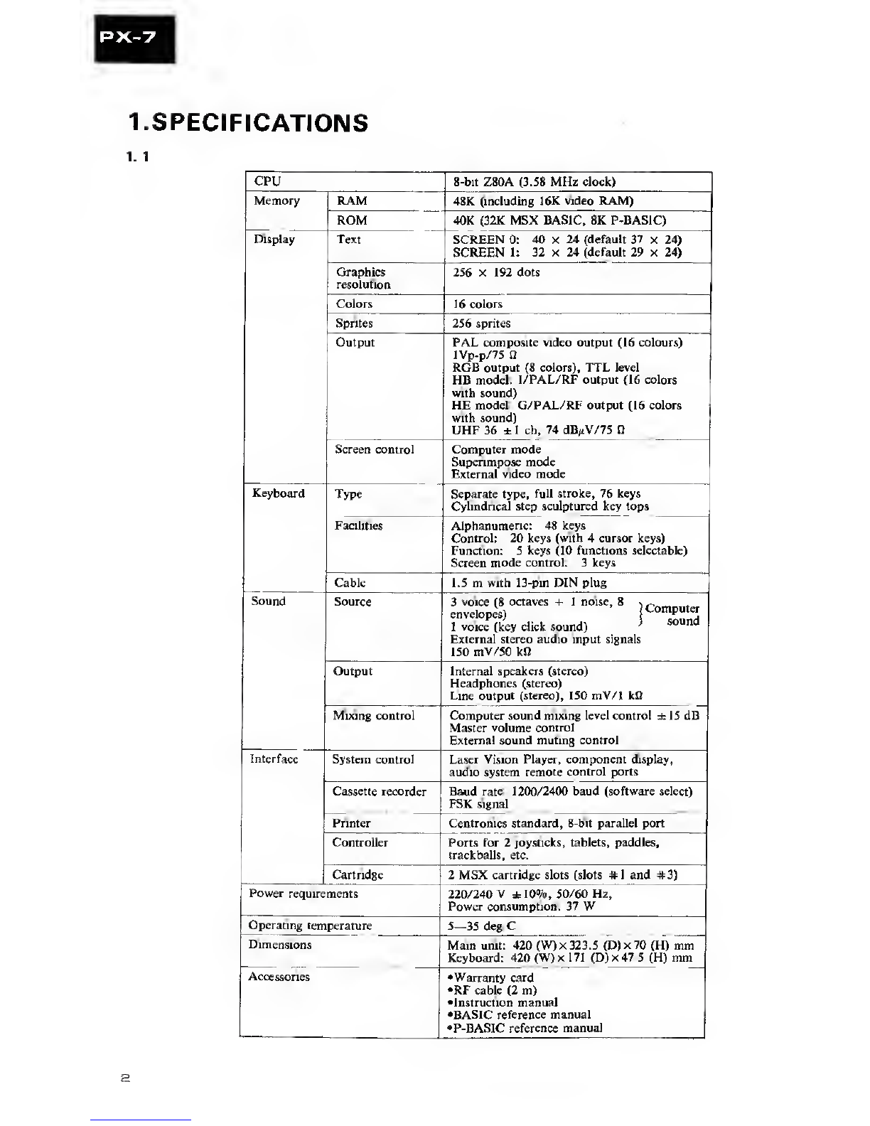
CPU 8-bit Z80A (3.58 MHz clock)
Memory RAM 48K (including 16K video RAM)
ROM 40K (32K MSX BASIC, 8K P-BASIC)
Display Text SCREEN 0: 40 X24 (default 37 x24)
SCREEN 1: 32 x24 (default 29 x24)
Graphics
resolution 256 x192 dots
Colors 16 colors
Sprites 256 sprites
Output PAL composite video output (16 colours)
lVp-p/75 fi
RGB output (8 colors), TTL level
HB model: I/PAL/RF output (16 colors
with sound)
HE model: G/PAL/RF output (16 colors
with sound)
UHF 36 ±1ch, 74 dB/tV/75 0
Screen control Computer mode
Superimpose mode
External video mode
Keyboard Type Separate type, full stroke, 76 keys
Cylindrical step sculptured key tops
Facilities Alphanumeric: 48 keys
Control: 20 keys (with 4cursor keys)
Function: 5keys (10 functions selectable)
Screen mode control: 3keys
Cable 1.5 mwith 13-pin DIN plug
Sound Source 3voice (8 octaves +1noise, 8~
envelopes) C°T“;
Ivoice (key click sound) }sound
External stereo audio input signals
150 mV/50 kfi
Output Internal speakers (stereo)
Headphones (stereo)
Line output (stereo), 150 mV/1 kfi
Mixing control Computer sound mixing level control ±15 dB
Master volume control
Externa! sound muting control
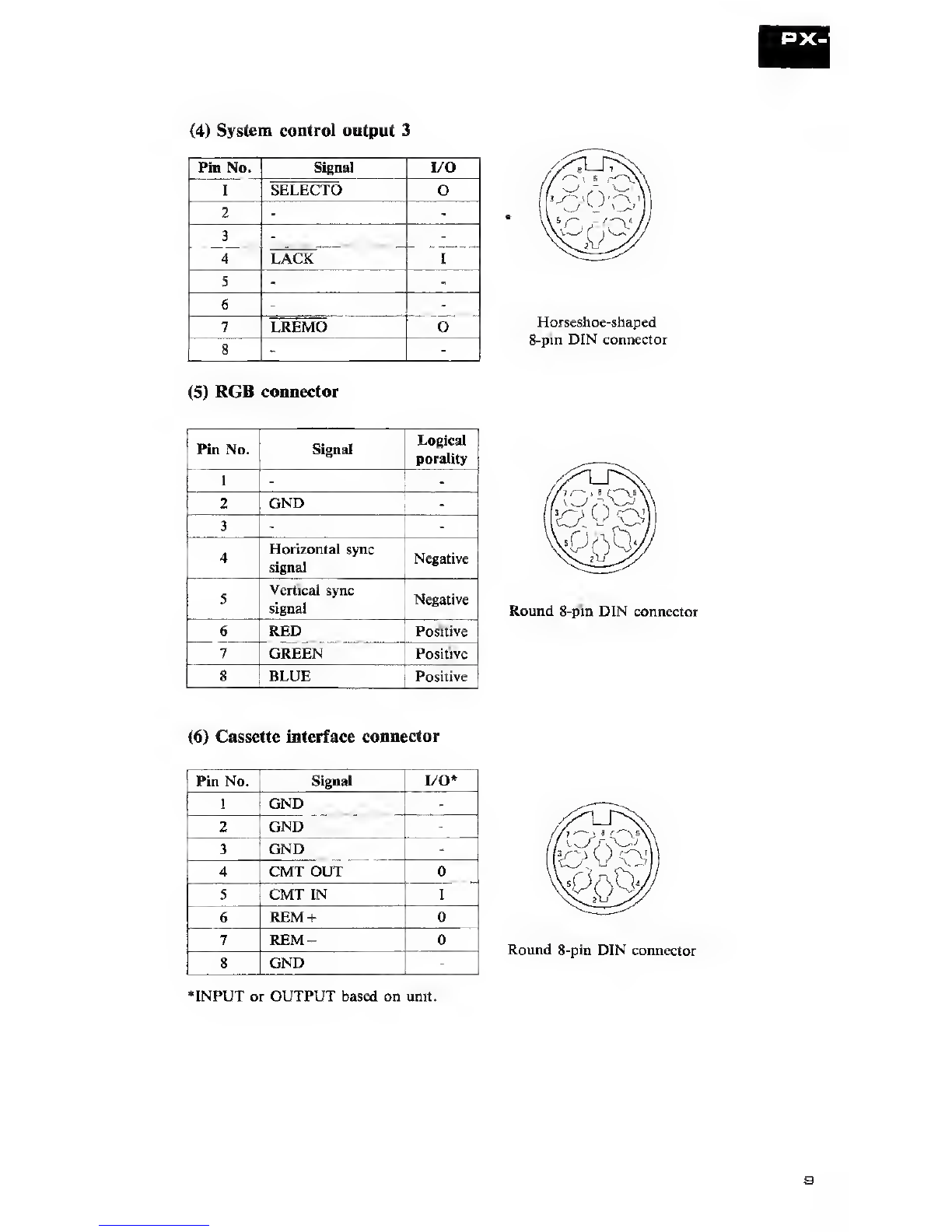
Interface System control Laser Vision Player, component display,
audio system remote control ports
Cassette recorder Baud rate: 1200/2400 baud (software select)
FSK signal
Printer Centronics standard, 8-bit parallel port
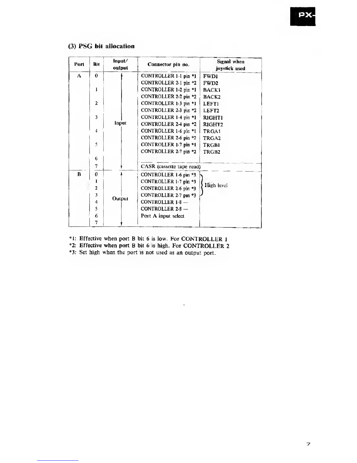
Controller Ports for 2joysticks, tablets, paddles,
trackballs, etc.
Cartridge 2MSX cartridge slots (slots #1and #3)
Power requirements 220/240 V±10%, 50/60 Hz,
Power consumption: 37 W
Operating temperature 5—35 deg.C
Dimensions Main unit: 420 (W)x 323.5 (D)x70 (H) mm
Keyboard: 420 (W)x 171 (D)x47.5 (H) mm
Accessories •Warranty card
•RF cable (2 m)
•Instruction manual
•BASIC reference manual
•P-BASIC reference manual

1.2 BLOCK DIAGRAM

1. 3MEMORY MAP
Hexadecimal addresses
0000|
User
area
MSX BASIC
ROM
Program area
(text area)
Variable area
Array variable area
Character string area
File control block
«Area in which programs with line
Inumbers are stored.
pVariable area
With character variables, the pointers
(string descriptors) to the character
strings provided are stored in this area.
•Array variable area
If the array variables are character
types, the pointers to the character
strings provided in the character string
area are stored in this area. The area
itself is secured when DIM statements
eexecuted or when arrays with 10 or
less accompanying characters are used.
•The free area is not used. Its size is
'determined by subtracting the stack
area, variable area and program area
from the user area. It can be sought by
the FRE function.
•Stack area in which BASIC returns and
addresses are saved when FOR-NEXT
>r GOSUB statements are executed.
fArea in which character strings includ-
ed in the character variables and array
variables are stored. The size of this
area is the size designated by the
CLEAR statement. An area of 200
bytes is secured if there is no designa-
tion with the CLEAR statement.
Area used with file input/output. It is
secured in line with the number
designated by the MAX FILES
statement.
»The upper limit address can be set to
F380 or less by CLEAR and so it is
possible to provide an area separate
from the work area which the user can
use freely for machine language
routines, etc.
>Area in which BASIC is used.

PX-7 Memory Configuration
Address Slot #0 Slot #1 Slot #2 Slot #3
Expansion
I/O register
Expansion
slot
(rear of unit)
1.4 I/O MAP
(1) I/O address allocation
RW Details Remarks
&H98 WData write into TMS9129NL
VRAM or
RData read from equivalent
VRAM
&H99 WCommand, address set
RStatus read
&HA0 WAddress latch AY-3-8910
&HA1 WData write or
&HA2 RData read equivalent
&HA8 WPort Adata write 8255A or
RPort Adata read equivalent
&HA9 WPort Bdata write
RPort Bdata read
&HAA WPort Cdata write
RPort Cdata read
&HAB WMode set
&H90 WStrobe output (bO) latch output
RStatus input (bl) “1” is
BUSY
&H91 WPrint data latch output
I/O addresses from 80 to FF area prescribed as
above for system use. Empty columns are system
reserves.
*1/0 addresses marked with an asterisk are for
optional equipment.

(2) PPI bit allocation
Port Bit Input/
output Signal Details
A0CSOL Slot designation number of ad-
dresses
1CSOH 0000 to 3FFF
2CS1L Slot designation number of ad-
dresses
3Ou put CS1H 4000 to 7FFF
4CS2L Slot designation number of ad-
dresses
5CS2H 8000 to BFFF
6CS3L Slot designation number of ad-
dresses
7CS3H C000 to FFFF
B0
S
7
Infut Keyboard return signal
C0KBO
2KB2 Keyboard scan signals
3Output KB3
4CASON Cassette control (L-ON)
5CASW Cassette write signal
6CAPS CAPS lamp signal (lights when low)
7SOUND Sound output based on software

(3) PSG bit allocation
Port Bit Input/
output Connector pin no. Signal when
joystick used
A0CONTROLLER 1-1 pin *1 FWD1
CONTROLLER 2-1 pin *2 FWD2
1CONTROLLER- 1-2 pin *1 BACK1
CONTROLLER 2-2 pin *2 BACK2
2CONTROLLER 1-3 pin *1 LEFT1
CONTROLLER 2-3 pin *2 LEFT2
3CONTROLLER 1-4 pin *1 RIGHTI
Input CONTROLLER 2-4 pin *2 RIGHT2
4CONTROLLER 1-6 pin *1 TRGA1
CONTROLLER 2-6 pin *2 TRGA2
5CONTROLLER 1-7 pin »1 TRGB1
6
CONTROLLER 2-7 pin *2 TRGB2
7CASR (cassette tape read)
B 0 CONTROLLER 1-6 pin *3
1
2CONTROLLER 2-6 pin *3 >High level
3Out >ut CONTROLLER 2-7 pin *3
4CONTROLLER 1-8 —
5CONTROLLER 2-8 -
6Port Ainput select
.
*1: Effective when port Bbit 6is low. For CONTROLLER 1
*2: Effective when port Bbit 6is high. For CONTROLLER 2
*3: Set high when the port is not used as an output port.

(4) Expansion I/O registers (slot #2)
LCON register <7FFE (16)>
Bit RW Signal Function
7
RACK Significant with acknowledge 1-»0
with respect to remote control signal
transmission
6
..
1
0
RRMCLOK Clock produced by dividing
CLK1/CLK2 frequency by 128
WREM High output with bit serial data out-
put generated in synchronization with
RMCLK
VCON register <7FFF (16)>
Bit RW Signal Function
7
REXTV Status indicating availability of exter-
nal video signal. Low when available;
high when not available.
WMute Line input signal muting
6
-^====;
|
1
0
R INTEXV Interrupt available with interrupt flag
1when external video signal is OFF.
Set to 0when read.
WOVERLAY Hardware selection signal of superim-
pose/non-superimpose mode; 0for
superimpose, 1for non-superimpose
1.5 CONNECTOR
(1) System control output 1
®vpRVOVLY (OUT)
©-^ yLEXTREMO(OUT)
Stereo mini-jack
(3) System control output 2
®vp©CREMO(OUT)
(?)
—
-U GND
(2) System control input
RSELECT I(IN)
LEXTREMI(IN)
Stereo mini-jack
®vri
©-^ y

(4)
System control output 3
Pin No. Signal I/O
1SELECTO o
2
3
4LACK I
5
6
7LREMO o
8
(5)
RGB connector
Horseshoe-shaped
8-pin DIN connector
Pin No. Signal Logical
porality
1
2GND
3
4Horizontal sync
signal Negative
5Vertical sync
signal Negative
6RED Positive
7GREEN Positive
8BLUE Positive
Round 8-pin DIN connector
(6)
Cassette interface connector
‘INPUT or OUTPUT based on unit.

(7) Keyboard interface connector
Pin No. Signal I/O
1D6 I
2D5 I
3D2 I/O
4D1 I/O
5D7 I
6D3 I
7D4 I/O
8DO I/O
9+5V
10 STB 0
11 GND
12 CAPS 0
13 GND
(8) Printer connector
Pin No. Signal I/O
1PSTB 0
2PDBO o
3PDB1 0
4PDB2 o
5PDB3 o
6PDB4 0
7PDB5 o
8PDB6 o
9PDB7 o
10 NC
11 BUSY I
12 NC
13 NC
14 GND
Round 13-pin connector
Amphenol 14-pin connector

(9) Controller connector
Pin No. Signal I/O
1FWD I
2BACK I
3LEFT I
4RIGHT I
5+5V
6TRG1 I/O
7TRG2 I/O
8OUTPUT o
9GND DSUB type 9-pin connector
(10) Cartridge connector
Pin No. Signal I/O* Pin No. Signal I/O*
1CST o2CS2 o
3CS12 o4SLTSL o
5Spare 6RFSH o
7WAIT I8INT .1
9Ml o10 BUSDIR I
11 IORQ 012 MERQ o
13 WR o14 RD o
15 RESET o16 Spare
17 A9 018 A15 0
19 All o20 A10 o
21 A7 o22 A6 0
23 A12 o24 A8 0
25 A14 o26 A13 o
27 A1 o28 A0 o
29 A3 o30 A2 o
31 A5 o32 A4 0
33 D1 I/O 34 DO I/O
35 D3 I/O 36 D2 I/O
37 D5 I/O 38 D4 I/O
39 D7 I/O 40 D6 I/O
41 GND 42 CLOCK o
43 GND 44 SW1
45 +5V46 SW2
47 +5V48 +12 V
49 SUNDIN I50 —12 V
Input or output based on unit.
2so
49
Note: The spare pins are not to be used.

2, PANEL FACILITIES
(1) FRONT PANEL FACILITIES
o©®
°L-l=^—111
--
-
@
—
[
®POWER indicator
This lights up red when power is supplied to the PX-7.
®POWER switch
Power is supplied to the PX-7 when this switch is pressed and the POWER
indicator lights. Press the switch again to turn off the power.
(D RESET switch
When this switch is pressed, the computer is reset and set to the same state
as when the power is turned on.
(?) VIDEO •AUDIO switch
This is used to select the output signals of the rear panel output terminals
(VIDEO/ AUDIO) or of the built-in speakers.
MNORMAL: The signals that pass through the PX-7’s circuitry are out-
put to the rear panel output terminals. The picture on
the connected display is selected by operating the screen
selector key on the keyboard.
mTHROUGH: The signals which were input to the rear panel input ter-
minals are output, without being passed through the
PX-7’s circuitry, to the rear panel output terminals. The
sound supplied from the PX-7 is heard through the built-
in speakers.
®KEYBOARD connector
The keyboard cable is connected here. Make sure that the cutout on the con-
nector is facing up and insert securely.
®CONTROLLER connectors (1, 2)
Connect a joystick or tablet to these connectors. When two units are connected,
the left-hand connector is treated as No. 1and the right-hand connector as
No. 2.
®PHONES jack
Connect the headphones to this jack. The sound from the built-in speakers
is no longer heard when the headphone plug is connected to this jack.

<D VOLUME control
Use this control to adjust the volume of the built-in speakers or headphones.
The volume is increased when the control is slid from MIN toward the MAX
setting.
(D MIXING LEVEL control
This adjusts the mixing level of the sound generated by the PX-7 and the ex-
ternal audio signals connected to the rear panel AUDIO INPUT terminals.
The sound generated by the PX-7 is increased when the control is slid from
the MIN toward the MAX setting.
@CARTRIDGE slot
Insert agame or other cartridge into this slot.
(2) REAR PANEL FACILITIES
G) AUDIO INPUT terminals (R, L)
Connect the external audio signals (such as the audio output of the video disc
player) to these terminals.
(2) AUDIO OUTPUT terminals (R, L)
Use these terminals to connect an external stereo amplifier. They are used when
the sound of the personal computer is to be passed through the stereo circuitry.
®VIDEO INPUT terminal
Connect the external video signal (such as the video output of the video disc
player) to this terminal.
®VIDEO OUTPUT terminal
This is connected to the video input terminal on adisplay unit.
{§) RF OUTPUT connector
This is used when aTV set without avideo input terminal is to be employed
as the display unit. Use the accessory RF cable to connect this terminal with
the antenna input terminal on the TV set.
©RGB OUTPUT connector
This is used when connection is made to adisplay unit equipped with an RGB
input connector.
®DATA RECORDER connector
Connect atape recorder to this connector.

(D EXPANSION SLOT
Agame cartridge or other cartridge, such as an MSX floppy disc drive car-
tridge, is plugged in here.
(D CHANNEL ADJUSTMENT knob
By turning this knob with asmall flat-bladed screwdriver, adjustments can
be made for ±1channel
O:+1ch (37 ch)
Ci :-1ch (35 ch)
(To SYSTEM CONTROL terminals
This is the input terminal of the control signal. Use it
when the unit is employed in combination with
PIONEER’S SD-26 component display unit.
The control signals from the PX-7 are output here. Use
it when the unit is employed in combination with
PIONEER’S SD-R5 RGB system control pack.
The control signals from the PX-7 are output here. Use
it when the unit is employed in combination with
PIONEER’S LD-1100 Laser vision player.
The control signals from the PX-7 are output here. Use
it when the unit is employed in combination with
PIONEER’S LD-700 Laser vision player.
Note:
See pages 18 through 21 when using the unit in combination with PIONEER’S SD-26
component display or with the LD-1100 or LD-700 Laser vision player.
(0 PRINTER connector
Connect the printer here.
•Removing the expansion slot cover
Acover is provided over the expansion slot on the rear panel of the computer
for shipment. Remove it, as shown in the figure, when using this slot. It can
be removed when the center part is pulled toward you and the hooks on the
left and right are disengaged.

(3) KEYBOARD
©Screen selector keys
These are used to select the screen on the display connected to the PX-7.
SUPERIMPOSE: The superimposed picture, resulting from the PX-7’s pic-
ture and the picture of the external video source which has
been connected to the video input terminal on the PX-7’s
rear panel, appears on the display.
VIDEO: The picture of the external video source which has been
connected to the PX-7’s video input terminal appears on
the display.
COMPUTER: The computer picture generated by the PX-7 appears on
the display.
(D Upper case indicator
This lights when the CAPS LOCK key is pressed to enter upper-case letters.
(3) Screen editing keys (CLS HOME, INS, DEL)
These keys are used to edit the letters displayed on the screen.
©Cursor keys
These are used to move the cursor vertically and horizontally.
(5) Function keys
When one of these keys is pressed, the character string defined by that key
is entered.

(4) KEY FUNCTIONS
The unit’s keyboard layout is shown below.
I"
!
!
•l;I." ;T* 1TI
1ri -1 e« rr ,*3 ;-r ^Tr.fV 1rafaTl
msmmmmmmmmmmamuB s@a
mMGEnogoBnanDmiH
sEBsaQQBQGniaDmmH es
m°aai memi
Keys indicated by in the figure are called special keys and are differentiated
from the other (character) keys. Adescription of the special keys is given first.
#Special Keys
fcuipj IThis key is used to type upper-case English letters, and characters
[ J indicated on the top part of the other character keys. A
1SHIFT Ikey is provided both on the left and right sides of
the keyboard; either key may be used.
This is used to type upper-case of the character which has lower-
case and uppercase. It is locked when pressed once and the lamp
to the left of the key top lights. It is released when pressed again.
When character keys are pressed with this key locked, upper-
case are typed and when the key is released, lowercase are typed.
This is used to type graphic characters. When acharacter key
ispressed when this key is pressed or when this key and the
ISHIFT Ikey are simultaneously pressed, graphic characters
are typed.
This is used to type special characters. When acharacter key
is pressed when this key is pressed or when this key and the
ISHIFT 1key are simultaneously pressed, special characters
are typed.
IB

•Character symbols displayed on the screen
When the alphanumeric keys are' pressed, the character symbols entered on
the screen change depending on whether the fSHIFT 1,IGRAPH-
]or
I" CODE 1keys, or a combination of those keys, are used, See below for more
details.
(a) When the alphanumeric keys alone are pressed:
=
SBBBHBBBBBBBEBBg BBS
ED EDBBBBQBBQElBmBBD
eedbbbbbbbbbbbbmJ m
EBBBBBBBBBBBEEB StB
ed °pibi ihnn
(b) When the alphanumeric keys are pressed while the 1SHIFT 1key is
depressed:
EEE
mSBBBBBBBBBBBBBg BBB
ED BBBBBBBBBBBQBnn
eebbbbbbbbbbbbbmj ed
ED EBBBBBBBBBBBEDO EDGE
=110[m
(c) When the alphanumeric keys are pressed while the |GRAPH Ikey is
depressed:
ES
SBBBBBBBBBBBBBBg BBB
ED SBBBBEQQEHtSBBtBl
ED EDDB00BBB00B0BEMJ ED
EBBBBBBBBBBBEDn EBGB
ED °snrIRm

(d) When the alphanumeric keys are pressed while the IGRAPH Iand
ISHIFT 1keys are depressed:
uu- i.4-jra
mBDDDDDQDDHBBQQg BBS
BB00B0OQfflBn®[H0rrl
E3bbsbqbdciisqsbeMJ m
ESBBGBDBBBBBBa EE
S°BH1IBI$I
(e) When the alphanumeric keys are pressed while the ICODE Ikey is depress-
ed:
E
mi BQHBQQEBEEEBQElg BBS
BSHHQQHHQQQmQGTD *
bqhbqqqqbqqqqeMJ m
SQQEB0Q00Q000 00
B°^HfIB m
(f) When the alphanumeric keys are pressed while the ICODE Iand
ISHIFT 1keys are depressed:
i-1-1rr
^SDBBBDBBBDBBDDg BBS
ED HBBBBDBHBBBBBnD
bebbbbbbbbbbbbbmJ m
SBBQQQ0O0DQ0B EDCD
E3 °8R IHED
INote:
•SCREENMODE0is for text only. Part ofthe graphic characterfont may disap-
pear. Use SCREENMODE 1when operating the alphanumeric keys together with
|the l~GRAPH Ikey.

•Character Keys
Several characters can be typed with asingle character key. The character to
be typed can be selected in combination with the special keys.
“+”and signify the following:
IAI+IBIPress the \~Bl key with the IAIkey depressed.
[~A~1 ,Press the f~A~| key once and keep in the IA1key mode.
Key pressed Typed character
m
1SHIFT 1+1P1
Icaps i, m
1CAPS 1, 1SHIFT I+[T]
TGRAPH 1+IPI
IGRAPH |+1SHIFT 1+IT!
1CODE 1+1P1
1CODE 1+1SHIFT I+m
P(Lower case)
P(Upper case)
P(Upper case)
P(Upper case)
B(Graphic symbol mode)
££ (Graphic symbol mode)
u(Special character mode)
n(Special character mode)
Key pressed Typed character
m
iSHIFT 1+m
icaps i. m
ICAPS 1, 1SHIFT |+m
1
1
f
1GRAPH 1+1 i 1
1CODE 1+m
1CODE 1+1SHIFT 1+m
Key pressed Typed character
m£
1SHIFT 1+P1
IGRAPH 1+1ii*
1GRAPH 1+1SHIFT 1+1l1*
I
-CODE 1+1I1a
1CODE 1+1SHIFT 1+1i12

PX-7
•SYSTEM CONFIGURATION
The PX-7 not only opens the door to system expansion with MSX-standard
peripheral units but also makes the most of its features through coupling with
avideo disc player. If aVCR and an audio system are further added, systems
completely unavailable in the past can be built up. The system configuration
of the PX-7 is shown in the figure below.
SD-26 Component
display unit
20
Table of contents
Other Pioneer Desktop manuals