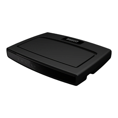
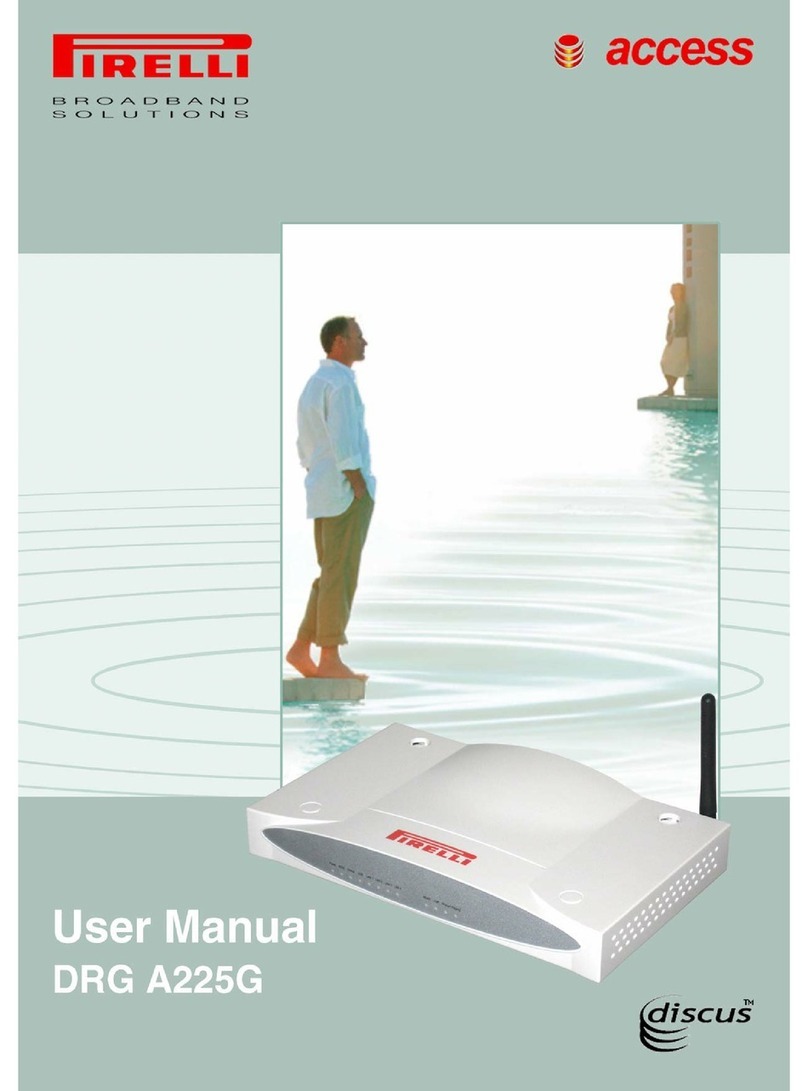
Pirelli DISCUS DRG A226G User manual

0

1
Ref. LED LED colour LED description
1POWERGreen/Red Solid Green - Power On
Solid Red - Boot Loader Failure
Off - Power Off
2EthernetGreen On - Ethernet Link established
Blinking - LAN activity present (traf-
fic in either direction)
Off - No Ethernet Link estab-
lished
3 Wireless
LAN Green On - Wireless functionality
enabled
Blinking - Wireless LAN activity
present (traffic in either
direction)
Off - Wireless functionality dis-
abled
4 USB Device Green On - USB Link Established
Blinking - USB activity present (traf-
fic in either direction)
Off - No USB Link established
5 Phone Green On - One of the FXS ports has
been registered with a SIP
proxy server
Blinking - One of the telephones is
off-hook
Off - Modem power off or
phone line 1 or 2 not regi-
stered
6 ADSL link Green On - DSL connected
Blinking - DSL attempting synchro-
nization
Off - No Cable connected/No
DSL line active
7Internet
Activity Green/Red Solid Green - WAN IP address
available (e.g. PPP active)
Blinking
Green - IP connected and IP traf-
fic is passing through
device (either direction)
Solid Red - WAN IP address not
available (e.g. PPP failure)
Off - Modem power off or the
modem is in bridged mode
or ADSL connection not
present
FRONT View

2
Your new DISCUS™ DRG A226G ADSL2+ Router kit contains the necessary hardware and soft-
ware to establish a connection to the network.
1. One DISCUS™ DRG A226G unit
2. One Switching Power Supply adapter
3. One ADSL micro filter*
4. One USB cable
5. One phone cable RJ-11 plug (ADSL)
6. One Ethernet CAT5 cable with RJ-45 plug
7. A CD-ROM containing:
•USBDriver
• User Manual
• Quick Installation Guide
8. One cradle
PORT DESCRIPTION
a Phone DSL connector (ADSL2/2+)
bFXOport
c FXS ports
d USB 2.0 Host port
e USB 1.1 Device port
f Four Ethernet ports 10/100 Mbps
g Reset to factory default button
h Power button
i Power connector
REAR View
Package Content
* Under Request

3
By purchasing your DISCUS™ DRG A226G unit you have entered into the world of broadband
Internet access. This Quick Installation Guide is meant to help you install your Router and establish
a connection from your computers to the Internet, quickly and easily.
Before starting you must ensure the following:
• Your computer has a Windows 98SE/ME/2000/XP or MAC 10.x Operating System with at least
60MB of free Hard Disk space and 128MB of RAM.
• You have a computer that has an Ethernet or an USB connection available.
• If you require wireless access, you must have a computer with a wireless 802.11b or 802.11g
adapter card installed.
• There are no other DHCP server devices on your local network that are responsible for allocating
IP addresses to your computers and other network connection devices.
• If one or more of these conditions are not met, refer to the comprehensive User Guide provided
on the accompanying CD-ROM for further guidance.
You should place the Router in such a location to ensure that:
• It is located near an electrical outlet and a phone wall socket.
• Water or moisture cannot enter the case of the unit.
• It is out of direct sunlight and away from sources of heat.
• The cabling is away from power lines, fluorescent lighting fixtures, and sources of electrical noise
such as radios, transmitters and broadband amplifiers.
• It is centrally located with respect to the wireless devices that will be connected to the Router. A
suitable location might be on top of a high shelf to ensure the maximum coverage for all con-
nected devices.
1
System Requirements
Positioning your Router
2

4
Before beginning installation you must locate devices in your house requiring a DSL filter such as
phones, fax machines, answering machines, dial-up modems, Satellite TV dialers or monitored
security systems and attach a DSL filter to any one of them sharing the same phone line as your
DSL router. To install DSL filters please follow these steps:
1. Disconnect the phone cable from the telephone wall socket.
2. Insert the phone cable into the DSL filter port identified with a phone symbol.
3. Insert the DSL filter cable into the telephone wall socket.
The first step to install the router is to physically connect it to the telephone socket and then to con-
nect it to a computer by means of an Ethernet or an USB connection.
To connect the phone cable:
1. Connect one end of the phone cable into the DSL filter port identified with a computer symbol
2. Connect the other end of the phone cable into the DSL port on the rear of the Router
You do not need to attach a DSL filter to unused wall sockets.
Installing Microfilters
3
Connecting the Router
4

5
To connect the Ethernet cable:
1. Connect one end of the Ethernet cable into one of the four Ethernet ports on the rear of the
Router
2. Connect the other end of the Ethernet cable into the Ethernet Network card of your computer
3. Verify if the Ethernet Network card is configured as DHCP client, otherwise configure it to remain
in the same local network of the router LAN interface
To connect the USB cable, follow the procedure according to your Operating System:
WINDOWS
1. Connect one end of the USB cable into the USB port of your PC
2. Browse till x:\USB driver folder (where “x” is the CD-ROM drive unit letter); launch the “setup.exe”
executable (“x:\USB driver\setup.exe”) and follow setup instructions
3. The setup software will invite you to plug the other end of the USB cable into the USB socket on
the rear of the Router

6
MAC 10.x
1. Connect one end of the USB cable into the USB port of your PC
2. Connect the other end of the USB cable into the USB port on the rear of the Router. The Opera-
ting System will automatically recognize the device
The Router setup program is web based, which means that it is accessed through your web
browser. To access to Router’s web server:
1. Launch your web browser on the computer
2. Enter the following URL in the location or address field of your browser:
http://192.168.1.1
3. You will be asked to insert an ID (namely a User name) and a Password. Insert them to access to
Router’s configuration panels. Two profiles are available:
• administrator account has unrestricted access to change and view configuration of the DSL
Router. The ID is “admin” and the Password is “admin”.
• user can access the DSL Router, view configuration settings and statistics, as well as, update
the router's software. The ID is “user” and the Password is “user“.
4. Follow parameters’ configuration according to User Manual instructions.
Accessing to the Router
5

7
OGU 930500142-A1
Table of contents
Other Pirelli Network Router manuals