CurrentLeakTM
Ground fault monitor
INTRODUCTION
This manual describes how to install this Whole Home Ground Fault Monitor,
CurrentLeakTM in a single phase service entrance combination panel. These
instructions do not cover all details or variations of service entrances, if you
require more information regarding a particular application that is not covered in
this manual, please contact a licensed/qualified electrical contractor.
WHEN INSTALLED ACCORDING TO THIS MANUAL, this product will provide
a visual display of the ground fault level in your entire electrical system. This
product will not prevent ground faults from occurring or prevent electrical fires
related to ground faults. In order to prevent electrical fires related to ground
faults, it is the sole responsibility of the end user to ensure their electrical
system is and remains free of all ground faults at all times.
THIS PRODUCT WILL NOT monitor and display ground fault levels in electrical
systems that are not grounded and/or do not have grounded branch circuits
and/or is not installed in accordance to the instructions in this manual. If you
have questions or require assistance, contact a licensed/qualified electrical
contractor.
THIS MANUAL PROVIDES PROCEDURES to isolate branch circuits that
contain ground faults, a licensed/qualified electrician shall repair all ground
faults.
IMPORTANT !
THIS PRODUCT SHALL BE INSTALLED by a licensed/qualified electrician in
accordance to the instructions in this manual, Canadian Electrical Code (CEC)
or National Electrical Code (NEC) or other applicable county codes, and any
applicable local codes. All applicable electrical codes supersede these
instructions.
THIS INSTALLATION REQUIRES REMOVING AND REPLACING the factory
installed neutral bond in the service entrance panel. Some jurisdictions may
have special requirements to permit the removal and replacement of a factory
installed neutral bond.
If you have questions or require assistance, contact a licensed/qualified
electrical contractor or the electrical authority in your jurisdiction.
WARNING! SHOCK HAZARDS
Improper installation and/or wiring can cause death, injury and/or
equipment damage.
Follow warnings and cautions. Completely read and understand the information
in this manual before attempting to install or operate this product. Only
licensed/qualified electricians who are trained in the installation and service of
electrical devices shall install and/or service this equipment.
KEEP THESE INSTRUCTIONS FOR FUTURE USE
©Pivotal Product Developments - All Rights Reserved
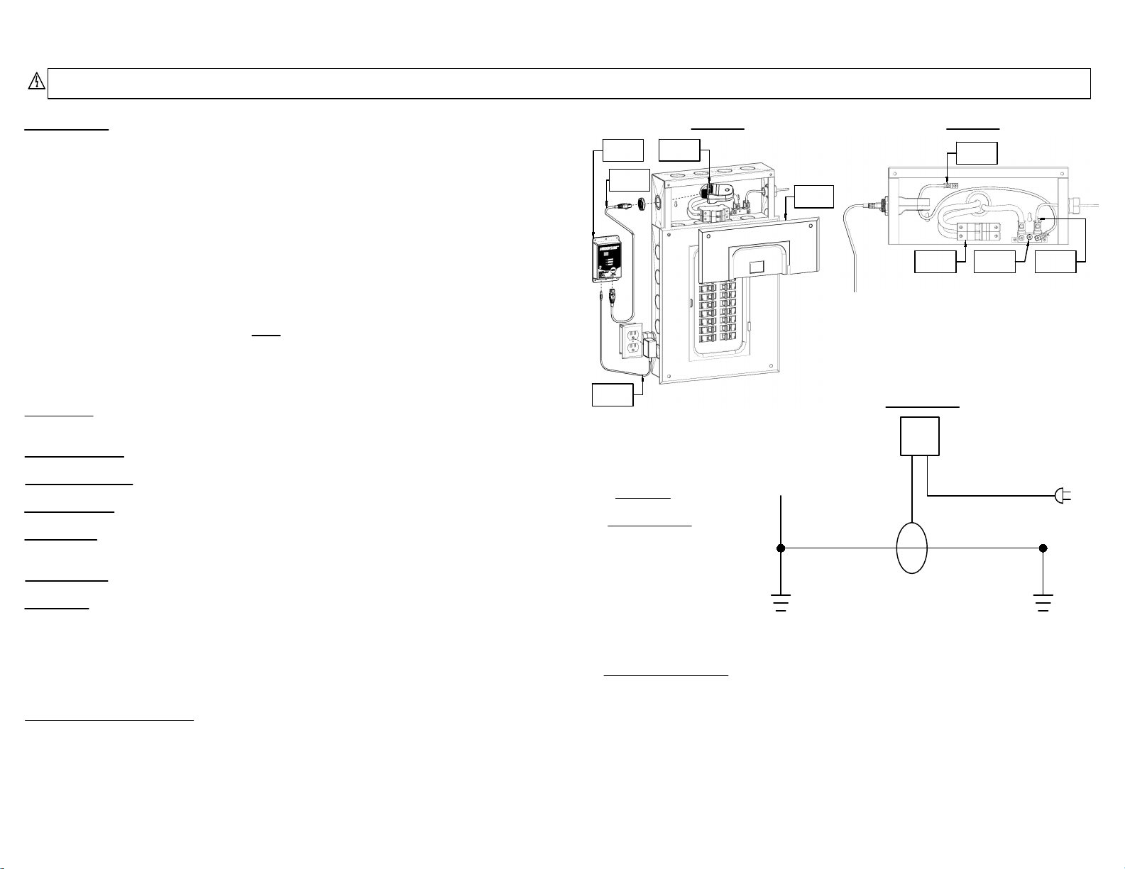
PARTS DESCRIPTION
CurrentLeakTM monitor Current transformer
Ethernet cable
9VDC power adaptor
Wire lugs X2
#6 AWG copper bonding cable
Mounting screws X4
Mounting wall anchors X4
SPECIFICATIONS
Patented WHOLE HOME
INSTALLATION
INSTRUCTIONS
FOR ONTARIO, CANADA ONLY
WHOLE HOME MONITORING REQUIRES REMOVING AND REPLACING the factory installed neutral bond
in the service entrance panel which is permitted in Ontario, Canada, pursuant to the Electrical Safety Authority
(ESA) Bulletin - Ground Fault Monitoring (2-024, 2-034, 10-210, 10-614 Whole Home Ground Fault Monitoring).
Model number MV1 CTV1
Description CurrentLeak monitor Current transformer
Intended use Indoor use, Max 400A service entrance panel
Operating conditions 5-40°C, 80% max RH at 5-31°C,
decreasing linearly to 50% max RH at 40°C
Altitude Max 2,000m
Input supply voltage 120v, 60Hz 9vDC
Output Voltage 9VDC N/A
Input current 0.132A 0-99mA
Max rated current 0.67A 70.995A
Dimensions W x H x D (mm) 83.8 x 136.4 x 27.9 48 x 95.5 x 38.5
W x H x D (in) 3.3 x 5.37 x 1.1 1.89 x 3.76 x 1.52
Pivotal Product Developments Ltd.
244 Brockport Drive, Unit 12, Toronto, ON M9W 6X9
WARRANTY AND EXCLUSIONS
Pivotal Product Developments Ltd warrants this product for a period of 1 year from the date of delivery to the purchaser to be free from defects in both workmanship and
material. Pivotal Product Developments Ltd assumes no risk or liability for the results of the use of the product purchased from it, including but without limiting the generality of
the foregoing: (1) The use in combination with any electrical or electronic components, circuits, systems, assemblies, or any other materials or substances; (2) Unsuitability of any
product for use in any circuit or assembly. Purchaser's rights under the warranty shall consist solely of requiring Pivotal Product Developments Ltd to repair, or at Pivotal Product
Developments Ltd's sole discretion, replace, free of charge, F.O.B factory, and defective items received at said factory within said term determined by Pivotal Product
Developments Ltd to be defective. The giving of or failure to give any advice or recommendations by Pivotal Product Developments Ltd shall not constitute any warranty by or
impose any liability upon Pivotal Product Developments Ltd.
The foregoing constitutes the sole and exclusive liability of Pivotal Product Developments Ltd AND IS IN LIEU OF ANY AND ALL OTHER WARRANTIES EXPRESSED, IMPLIED OR
STATUTORY AS TO THE MERCHANTABILITY, FITNESS FOR THE PURPOSE SOLD, DESCRIPTION, QUALITY, PRODUCTIVENESS OR ANY OTHER MATTER. In no event shall Pivotal
Product Developments Ltd be liable for special or consequential damages or for delay in performance of the warranty. This warranty does not apply if the product has been
misused, abused, altered, tampered with, or used in applications other than specified in the manual. At the end of the warranty period, Pivotal Product Developments Ltd shall be
under no further warranty obligation expressed or implied. The product covered by this warranty certificate can only be repaired or replaced by the factory. Repair or
replacement units will be return collected. If Pivotal Product Developments Ltd finds the return to be a manufacturer's defect, the product will be return prepaid.
RETURN POLICY
The purchaser may return the product in it's original packaging, prepaid, within thirty (30) days of the original purchase date for a full refund of the purchase price, not including
freight or shipping charges that may have been paid by the purchaser as part of the original purchase. A copy of the original invoice must be included with the returned product.
Pivotal Product Developments will promptly issue a refund providing that the product is not damaged or in non re-sellable condition. Pivotal Product Developments is under no
obligation to provide a refund if it finds, at it's sole discretion, that the product is damaged or in non re-sellable condition.
Pivotal Product Developments Ltd.
Att: Quality Assurance Department, 244 Brockport Drive, Unit 12 Toronto, Ontario M9W 6X9