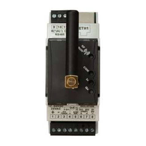
Pixsys CNV580 User manual

User manual - Manule d’uso
CNV580
Hub for remote monitoring
of Pixsys devices
Hub per il controllo remoto
di dispositivi Pixsys


Table of contents
1 Safety guidelines ................................................................................................................8
1.1 Organization of safety notices ...................................................................9
1.2 Safety Precautions .........................................................................................9
1.3 Precautions for safe use............................................................................. 10
1.4 Environmental policy / WEEE....................................................................12
2 Dimensions and installation.........................................................................................13
2.1 Model identification....................................................................................14
3 Technical data...................................................................................................................14
3.1 General features ...........................................................................................14
3.2 Reference standards....................................................................................15
3.3 Hardware data..............................................................................................15
3.4 Isolation data ............................................................................................... 16
4 Electrical wirings.............................................................................................................. 16
4.a Power supply..............................................................................................................17
4.b Digital output PNP....................................................................................................17
4.c Input AI1 4...20 mA................................................................................................... 18
4.d Pin +V .......................................................................................................................... 18
4.e Examples of connection for AI1 input .................................................................19
4.f Isolated digital inputs..............................................................................................19
4.g Isolated RS485 (only for CNV580-LTE-2AD) ...................................................... 20

4.h Antenna...................................................................................................................... 20
4.i Leds.............................................................................................................................. 21
4.j Association button and led (Internal)................................................................ 23
4.k UPS power on / shutdown ..................................................................................... 23
5 Wiring examples.............................................................................................................. 24
5.a CNV580 + ATR144-ABC-T........................................................................................ 24
5.b CNV580 + ATR244-12ABC-T ................................................................................... 25
5.c CNV580 + ATR621-13ABC-T.................................................................................... 25
5.d CNV580 + DRR244-13ABC-T .................................................................................. 26
5.e CNV580 + MCM260X-xAD ..................................................................................... 27
6 App “Pixsys Guard” ......................................................................................................... 28
6.a Prerequisites.............................................................................................................. 28
6.b Admin mode (only Android® version)................................................................. 28
6.c Association mode.................................................................................................... 28
6.d Plant acquisition and implementation.............................................................. 29
6.e More details and plant sharing............................................................................ 29
6.f Plant dashboard and panels ................................................................................ 30
6.g Network...................................................................................................................... 30
6.h Notification Log ........................................................................................................31
6.i Default configuration..............................................................................................31
7 Complete user manual “Pixsys Guard” App for:...................................................... 32
8 Limited warranty............................................................................................................. 33

Indice degli argomenti
1 Norme di sicurezza.......................................................................................................... 35
1.1 Organizzazione delle note di sicurezza ................................................ 36
1.2 Note di sicurezza ......................................................................................... 36
1.3 Precauzioni per l’uso sicuro...................................................................... 38
1.4 Tutela ambientale e smaltimento dei rifiuti / Direttiva WEEE ......... 40
2 Dimensioni ed installazione......................................................................................... 41
2.1 Identificazione del modello...................................................................... 41
3 Dati tecnici ........................................................................................................................ 42
3.1 Caratteristiche generali............................................................................. 42
3.2 Normative di riferimento .......................................................................... 42
3.3 Caratteristiche hardware.......................................................................... 43
3.4 Caratteristiche di isolamento .................................................................. 43
4 Collegamenti elettrici..................................................................................................... 44
4.a Alimentazione .......................................................................................................... 45
4.b Uscita digitale PNP .................................................................................................. 45
4.c Ingresso AI1 4..20 mA.............................................................................................. 45
4.d Morsetto +V............................................................................................................... 46
4.e Esempi di collegamento per ingresso AI1.......................................................... 46
4.f Ingressi digitali isolati............................................................................................. 47
4.g Seriale RS485 isolata (solo per CNV580-LTE-2AD) .......................................... 47

4.h Antenna...................................................................................................................... 48
4.i Led frontali ................................................................................................................ 48
4.j Pulsante di associazione e led (Interni).............................................................. 50
4.k UPS accensione / spegnimento............................................................................ 50
5 Esempi di collegamento................................................................................................ 51
5.a CNV580 + ATR144-ABC-T........................................................................................ 51
5.b CNV580 + ATR244-12ABC-T ................................................................................... 52
5.c CNV580 + ATR621-13ABC-T.................................................................................... 52
5.d CNV580 + DRR244-13ABC-T .................................................................................. 53
5.e CNV580 + MCM260X-xAD ..................................................................................... 54
6 App “Pixsys Guard” ......................................................................................................... 55
6.a Prerequisiti................................................................................................................. 55
6.b Modalità Admin (solo versione Android®) ........................................................ 55
6.c Modalità associazione........................................................................................... 55
6.d Acquisizione e creazione impianto..................................................................... 56
6.e Dettagli e condivisione impianto........................................................................ 56
6.f Dashboard impianto e pannelli .......................................................................... 57
6.g Network...................................................................................................................... 57
6.h Notification Log ....................................................................................................... 58
6.i Configurazione di default...................................................................................... 58
7 Manuale completo App“Pixsys Guard” per dispositivi:......................................... 60
8 Limitazione di responsabilità........................................................................................61

User manual - CNV580 - 7
Download “Pixsys Guard” App for device:
Android® iOS®
Use App only after checking user manual. Check chapter 6for details.
Android® app features iOS® app features
• CNV installation
• System configuration, slaves and
connections
• Advanced notifications editor
• CNV acquisition and panels
configuration
• User notifications editor
Table of contents

8 - CNV580 - User manual
1 Safety guidelines
Read carefully the safety guidelines and programming instructions contained
in this manual before connecting/using the device.
Disconnect power supply before proceeding to hardware settings or electrical
wirings to avoid risk of electric shock, fire, malfunction. Do not install/operate
the device in environments with flammable/explosive gases. This device has
been designed and conceivedfor industrialenvironmentsandapplicationsthat
rely on proper safety conditions in accordance with national and international
regulations on labour and personal safety. Any application that might lead to
serious physical dama ge/ life risk or involve medical life support devices should
be avoided. Device is not conceived for applications related to nuclear power
plants, weapon systems, flight control, mass transportation systems. Only
qualified personnel should be allowed to use device and/or service it and only
in accordance to technical data listed in this manual. Do not dismantle/modify/
repair any internal component. Device must be installed and can operate only
within the allowed environmental conditions. Overheating may lead to risk of
fire and can shorten the lifecycle of electronic components

User manual - CNV580 - 9
1.1 Organization of safety notices
Safety notices in this manual are organized as follows:
Safety notice Description
Danger! Disregarding these safety guidelines and notices can be
life-threatening.
Warning! Disregarding these safety guidelines and notices can result in
severe injury or substantial damage to property.
Information! This information is important for preventing errors.
1.2 Safety Precautions
Danger!
CAUTION - Risk of Fire and Electric Shock.
This product is UL listed as open type process control equipment.
It must be mounted in an enclosure that does not allow fire to
escape externally.

10 - CNV580 - User manual
Warning!
If the output relays are used past their life expectancy, contact
fusing or burning may occasionally occur.
Always consider the application conditions and use the output
relays within their rated load and electrical life expectancy. The
life expectancy of output relays varies considerably with the
output load and switching conditions.
Warning! Loose screws may occasionally result in fire.
For screw terminals tighten screws to tightening torque of 0,5 Nm.
Warning!
A malfunction in the Digital Controller may occasionally make
control operations impossible or prevent alarm outputs, resulting
in property damage. To maintain safety in the event of malfunction
of the Digital Controller, take appropriate safety measures, such as
installing a monitoring device on a separate line.
1.3 Precautions for safe use
Be sure to observe the following precautions to prevent operation failure,
malfunction, or adverse affects on the performance and functions of the
product. Not doing so may occasionally result in unexpected events. Do not
handle the Digital Controller in ways that exceed the ratings.
• The product is designed for indoor use only. Do not use or store the product

User manual - CNV580 - 11
outdoors or in any of the following places.
- Places directly subject to heat radiated from heating equipment.
- Places subject to splashing liquid or oil atmosphere.
- Places subject to direct sunlight.
- Places subject to dust or corrosive gas (in particular, sulfide gas and
ammonia gas).
- Places subject to intense temperature change.
- Places subject to icing and condensation.
- Places subject to vibration and large shocks.
• Installing two or more controllers in close proximity might lead to increased
internal temperature and this might shorten the life cycle of electronic
components. It is strongly recommended to install cooling fans or other
air-conditioning devices inside the control cabinet.
• Always check the terminal names and polarity and be sure to wire properly.
Do not wire the terminals that are not used.
• To avoid inductive noise, keep the controller wiring away from power
cables that carry high voltages or large currents. Also, do not wire power
lines together with or parallel to Digital Controller wiring. Using shielded
cables and using separate conduits or ducts is recommended. Attach a
surge suppressor or noise filter to peripheral devices that generate noise
(in particular motors, transformers, solenoids, magnetic coils or other

12 - CNV580 - User manual
equipment that have an inductance component). When a noise filter is
used at the power supply, first check the voltage or current, and attach
the noise filter as close as possible to the Digital Controller. Allow as much
space as possible between the
Digital Controller and devices that generate
powerful high frequencies (high-frequency welders, high-frequency sewing
machines, etc.) or surge.
• A switch or circuit breaker must be provided close to device. The switch
or circuit breaker must be within easy reach of the operator, and must be
marked as a disconnecting means for the controller.
• The device must be protected by a fuse 2A (cl. 9.6.2).
• Wipe off any dirt from the Digital Controller with a soft dry cloth. Never
use thinners, benzine, alcohol, or any cleaners that contain these or other
organic solvents. Deformation or discoloration may occur.
• The number of non-volatile memory write operations is limited. Therefore,
use EEprom write mode when frequently overwriting data, e.g.: through
communications.
1.4 Environmental policy / WEEE
Do not dispose electric tools together with household waste material. According
to European Directive 2012/19/EU on waste electrical and electronic equipment

User manual - CNV580 - 13
and its implementation in accordance with national law, electric tools that have
reached the end of their life must be collected separately and returned to an
environmentally compatible recycling facility.
2 Dimensions and installation
COM
RF
RUN
Ix
Qx
9
12345678
10 11
B(+)
+V
70mA 4/20
mA
DI1 DI2 DI
0V(PNP)
AI1
O1 mA
A(-) C
RS485
12.. 24V DC
24VAC
ISOLATION
ISOLATION
9
1 2 3 4 5 6 7 8
10 11
B(+)
+V
70mA 4/20
mA
DI1 DI2 DI
0V(PNP)
AI1
O1 mA
A(-) C
RS485
12.. 24V DC
24VAC
ISOLATION
ISOLATION
CNV580-4AD
GATEWAY IoT-NB BLE 4.2 NFC
WI-FI 802.11 B/G/N
MADE IN
EU
Power Supp. 12 24VDC/24VAC 50/60Hz
Power Consumption: 5VA
2DI 1AI 1DO RS485 ETH CAN
Extractable
terminal blocks
84 mm36 mm
90 mm
82 mm
DIN rail mounting guide EN50022 Button
(internal)
Led
(internal)

14 - CNV580 - User manual
2.1 Model identification
CNV580-LTE-1AD Gateway IoT LTE / 4G 2DI / 1AI 4-20mA 1DO
CNV580-LTE-2AD Gateway IoT LTE / 4G + RS485 Modbus / 2DI 1AI 4-20mA
1DO
3 Technical data
3.1 General features
Power supply 12..24VDC / 24 VAC ±15%
Consumption Typical 2 W - Max 12 W (for UPS start-up)
Op. condition Temperature 0-45 °C, humidity 35..95 RH%
Enclosure 36x90x84 mm (DIN43880, 2 modules, DIN rail mounting)
Material Enclosure: Noryl V0 self-exstinguish
Sealing IP20 (enclosure and terminal block)
APP Programming via App
“Pixsys Guard”
for Android® and
iOS systems
IoT Radio network Multi-band LTE / 4G GPRS EDGE module
Weight approx 250 gr.

User manual - CNV580 - 15
3.2 Reference standards
• EMC DIRECTIVE 2014/52/EU (EMC)
• RADIO EQUIPMENT DIRECTIVE 2014/53/EU (RED)
• RoHS 2011/65/EU, 2015/863/EU
3.3 Hardware data
1 analogue input
4...20mA 2 wires, current/loop (30000 points)
±0,2% F.S. - min. 100 milliseconds (1...30 mean
filter)
2 digital inputs PNP , galvanic isolation 2.5 kV
1 digital output PNP 24 VDC - 30 mA max
Serial communication RS485 - only for Pixsys devices (CNV580-LTE-2AD
only)
SIM slot
Nano Sim preinstalled and already activated.
Do not remove it unles authorized by the
manufacturer/Pixsys.

16 - CNV580 - User manual
3.4 Isolation data
9
1 2 3 4 5 6 7 8
10 11
B(+)
+V
70mA 4/20
mA
DI1 DI2 DI
0V(PNP)
AI1
O1 mA
A(-) C
RS485
12..24VDC
24VAC
ISOLATION
ISOLATION
The 3 sections of the device are completely isolated.
Isolation:1500 VAC
4 Electrical wirings
This product has been designed and manufactured in conformity to Low
Voltage Directive 2006/95/EC, 2014/35/EU (LVD) and EMC Directive 2004/108/
EC, 2014/30/EU (EMC). For installation in industrial environments please
observe following safety guidelines:
• Separate control line from power wires.
• Avoid proximity of remote control switches, electromagnetic contactors,
powerful engines.
• Avoid proximity of power groups, especially those with phase control.

User manual - CNV580 - 17
• It is strongly recommended to install adequate mains filter on power supply
of the machine where the controller is installed, particularly if supplied
230 VAC. The device is designed and conceived to be incorporated into
other machines, therefore CE marking on the controller does not exempt
the manufacturer of machines from safety and conformity requirements
applying to the machine itself.
• Wiring device, use crimped tube terminals or flexible/rigid copper wire
with diameter 0.14 to 1.5 mm2(min. AWG28, max. AWG16). Cable stripping
lenght is 7 mm.
• It is possible to connect on a single terminal two wires with same diameter
comprised between 0.14 and 0.75mm2.
4.a Power supply
1
+ -
2
SUPPLY
12...24 V AC / DC ± 15%
4.b Digital output PNP
3+V Q1-4
LOAD
Q1-: PNP output max. 30 mA.

18 - CNV580 - User manual
4.c Input AI1 4...20 mA
3
+V AI1
5
mA
For linear signals
• Rispect polarity
• When using shielded cable, only one shield end
must be grounded.
• Pin AI1: 4...20 mA signal input
4.d Pin +V
3
+V
Output for sensor supply (Max. 70mA).
If device supply is DC, +V = supply voltage.
If device supply is AC, +V = supply voltage x 1,41 V DC ,
hence rectified supply output. With supply 24 V AC, +V
will be approx. 34 V DC.

User manual - CNV580 - 19
4.e Examples of connection for AI1 input
4...20mA
P:0...100mbar
Pmax :3bar
T:0..70°C
OUT: 4...20mA
IN :9...33V DC
3
5
For 0/4..20 mA normalized current signals with two wire
sensor.
Respect the polarity:
5 = Sensor output
3 = Power supply (12...34 V DC)
In the picture: pressure sensor.
4.f Isolated digital inputs
6
DI1 0V
8
DI2
7
12..24 V AC / DC
PNP inputs (to activate input, connect a positive signal
to corresponding pin)
1,5 kV galvanic isolation

20 - CNV580 - User manual
4.g Isolated RS485 (only for CNV580-LTE-2AD)
Shield
Schermo
9
CA-B+
10 11
RS485:
330Ω Terminator
470Ω Polarizer
4.h Antenna
Frequency range: 850 / 900 / 1800 / 1900/ 2100 MHz
M2M Applications
Connector: SMA (male)
Dimensions: 18.4 x 8.0 x 49.5mm
Nominal impedence: 50Ω
Radiation Pattern Omni
Polarization: Linear
Table of contents
Languages:
Other Pixsys Switch manuals
Popular Switch manuals by other brands

Amcrest
Amcrest AMPS9E8P-AT-96 user manual

HP
HP AK241A - StorageWorks 8Gb Simple SAN... Cli guide

enika
enika Tx PSMR16 Instructions for installation and use

Festo
Festo CRSMT-8 series instructions

American Dynamics
American Dynamics AD1416 Installation and operating instructions

ZyXEL Communications
ZyXEL Communications GS-105A Specifications