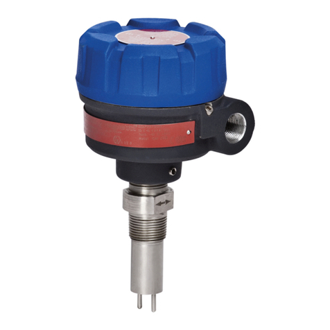
Ametek Drexelbrook IntelliPoint RF RNL Series User manual

Leader in
Level Measurement
Installation and
Operating Instructions
IntelliPoint RFTM RNL Series
Point Level Switch
NOTICE: The AutoVerify™ feature in The
IntelliPoint™ switch is shipped DISABLED.
For critical High Level applications we
recommend enabling the AutoVerify™
feature.
Telephone: +1 215-674-1234
Fax: +1 215-674-2731
Website: www.drexelbrook.com

AMETEK Drexelbrook makes no warranty of any kind with regard to the material
contained in this manual, including, but not limited to, implied warranties or fitness for
a particular purpose. Drexelbrook shall not be liable for errors contained herein or for
incidental or consequential damages in connection with the performance or use of
material.
© AMETEK Drexelbrook

205 Keith Valley Road, Horsham, PA 19044
Telephone: +1 215-674-1234
Fax: +1 215-674-2731
Website: www.drexelbrook.com
An ISO 9001 Certified Company
IntelliPoint RF Series
Point Level Switch
RNLXX1-LM
Issue# 25

Contents

Contents
Section 1: Introduction
1.1 System Description ......................................................................................1
1.2 Technology...................................................................................................1
1.3 Model Number .............................................................................................2
1.4 Sensing Element List ..................................................................................3
1.5 Dual Compartment Housing .......................................................................4
1.6 Spare Parts List ...........................................................................................5
Section 2: Installation
2.1 Unpacking ....................................................................................................7
2.2 Mounting and Installation Guidelines ...........................................................7
2.3 Input Wiring..................................................................................................9
2.4 Output Wiring - Relay Version ......................................................................10
2.5 Spark Protection ..........................................................................................10
2.6 Circuit Board ...............................................................................................11
2.7 Output and LED Status................................................................................14
2.8 Sensing Element Connection.......................................................................15
Section 3: Calibration
3.1 Calibration....................................................................................................17
3.2 Re Calibration ..............................................................................................18
3.3 IntelliPoint Calibration Mode Change...........................................................19
Section 4: Troubleshooting
4.1 RF Point Level Troubleshooting Guide .........................................................21
4.2 Testing Electronic Unit .................................................................................22
4.3 Over Range..................................................................................................23
4.4 Under Range................................................................................................23
4.5 Testing The Relay Circuits ...........................................................................23
4.6 Testing The Sensing Element ......................................................................24
4.7 Testing the Integral Cable ............................................................................27
4.8 Testing the Remote Cable............................................................................27
4.9 Testing the Power Supply.............................................................................30
4.10 Factory Assistance.......................................................................................31
4.11 Field Service ................................................................................................31
4.12 Customer Training ........................................................................................31
4.13 Equipment Return........................................................................................32
Section 5: Specifications
5.1 Specifications...............................................................................................32
5.2 Approvals Available:.....................................................................................33
Section 6 : Control Drawings / Certificates
6.1 FM / FMc Control Drawings .........................................................................34
6.2 ATEX Control Drawings................................................................................48
6.3 CE Declaration of Conformity ......................................................................57
6.4 IECEX Control Drawings..............................................................................58
6.5 Mounting and Wiring for Spark Protector Drawings .....................................67
6.6 Adding a Padded Capacitor .........................................................................70
6.7 Dual Seal Assembly for 700 Series Sensing Elements................................73
Appendix A:
Shortening or Lengthening the Sensing Element...................................................A-1
CE Installation Supplement.......................................................................................A-2
CE Installation Supplement (Continued) .................................................................A-3

Section 1

Introduction
1
Section 1: Introduction
1.1 System Description
Installation of the AMETEK Drexelbrook IntelliPoint™
Series Products is simple and easy. Simply apply power and
IntelliPoint system is ready to detect the presence or absence
of material. Since IntelliPoint instrument does not require
calibration or setpoint adjustments, it is capable of operating in
non-dedicated tanks regardless of the material being measured.
Notice: Material to be Measured Must Be Below
Sensor when Power is Applied.
The AutoVerify™ self-testing function continuously monitors
the entire system to ensure proper operation. Manual
Certify™ changes the outputs in order to test the loop current
and ensure proper operation of the control systems.
1.2 Technology
In a simple capacitance probe-type sensing element, when
the level rises and material covers the probe, the capacitance
within the circuit between the probe and the media (conductive
applications) or the probe and the vessel wall (insulating
applications) increases. This is due to the dielectric constant
(k) of the material, which causes a bridge mis-balance. The
signal is demodulated (rectied), amplied, and the output is
increased. There are drawbacks, however, especially when
there is coating of the probe.
An RF Admittance level transmitter is the next generation.
Although similar to the capacitance concept, IntelliPoint
employs a radio frequency signal and adds the Cote-Shield™
circuitry within the Electronics Unit.
This patented Cote-Shield™ circuitry is designed into the
IntelliPoint series and enables the instrument to ignore the
effect of buildup or material coating on the sensing element. The
sensing element is mounted in the vessel and provides a change
in RF admittance indicating presence or absence of material.
The Cote-Shield element of the sensor prevents the
transmission of RF current through the coating on the sensing
element. The only path to ground available for the RF current
is through the material being measured.
The result is an accurate measurement regardless of the amount
of coating on the probe, making it by far the most versatile
technology. It is suitable for very wide range conditions and
materials from cryogenics to high temperature, from vacuum
to 10,000psi pressure.
Figure 1-1
Simple Capacitance Probe
(Insulating Media Shown)
k
air
A
d
Ckmedia
C=kA
d
C = k A
d
A
k
air
d
C
kmedia
Figure 1-2
RF Admittance Probe
with Cote-Shield

RNLXX1 - IntelliPoint RF Series User's Manual
2
1.3 Model Number
Sensing Element (Reference Section 1.4 for Probe Selections)
IL CSL
xxxG 457 mm (18") 0 mm (0")
xxxH 914 mm (36") 254 mm (10")
xxxJ 914 mm (36") 0 mm (0")
xxxK 1219 mm (48") 254 mm (10")
xxxL 1524 mm (60") 254 mm (10")
P00X IL/CSL Other
A1BX IL/CSL factory set for Fly Ash
xxxZ Other
IL CSL
xxx1 457 mm (18") 152 mm (6")
xxx2 305 mm (12") 152 mm (6")
xxxA 152 mm (6") 51 mm (2")
xxxB 305 mm (12") 51 mm (2")
xxxC 305 mm (12") 89 mm (3.5")
xxxD 457 mm (18") 51 mm (2")
xxxE 457 mm (18") 89 mm (3.5")
xxxF 457 mm (18") 254 mm (10")
Mounting Type (See separate Mounting Chart for first three digits)
(1) Available with remote electronics only
(2) Use A1P mounting option
(3) Choose only sanitary mounting options
(4) Available with 0-inch CSL only
(5) Use P00X mounting option
(6) Use A1B mounting option
(7) Use A8B mounting option (¼-inch NPT)
(8) Choose from flange mounting only
(9) FM approved with remote electronics only
Not all mounting options available with all
sensing elements
Notes: CSL (Cote-Shield Length) should extend through Nozzle + Typical "Wall Buildup" + 2 Inches
NPT Threads
A1B ¾"NPT 316SS
A1C ¾"NPT Hastelloy C
A1P ¾"NPT PFA
A2B 1"NPT 316SS
A2C 1"NPT Hastelloy C
Sanitary TriClamps
C2B 1"TriClamp 316SS
C3B 1½"TriClamp 316SS
C4B 2"TriClamp 316SS
C5B 2-1/2"TriClamp 316SS
C6B 3 "TriClamp 316SS
C7B 3 "TriClamp 316SS
ANSI Flanges
DA1 1" 150# RF 316/316L SS
DB1 1½" 150# RF 316/316L SS
DC1 2" 150# RF 316/316L SS
DD1 2½" 150# RF 316/316L SS
DE1 1" 300# RF 316/316L SS
DF1 1½" 300# RF 316/316L SS
DG1 2" 300# RF 316/316L SS
DH1 2½" 300# RF 316/316L SS
DI1 3" 150# RF 316/316L SS
DJ1 3" 300# RF 316/316L SS
DK1 4" 150# RF 316/316L SS
DL1 4" 300# RF 316/316L SS
DM1 6" 150# RF 316/316L SS
DN1 6" 300# RF 316/316L SS
DA2 1" 150# RF CS
DB2 1½" 150# RF CS
DC2 2" 150# RF CS
DD2 2½" 150# RF CS
DE2 1" 300# RF CS
DF2 1½" 300# RF CS
DG2 2" 300# RF CS
DH2 2½" 300# RF CS
DI2 3" 150# RF CS
DJ2 3" 300# RF CS
DK2 4" 150# RF CS
DL2 4" 300# RF CS
DM2 6" 150# RF CS
DN2 6" 300# RF CS
DIN Flanges
E01 25 mm 16 bar RF 316/316L SS
EP1 25 mm 40 bar RF 316/316L SS
EQ1 50 mm 16 bar RF 316/316L SS
ER1 50 mm 40 bar RF 316/316L SS
ES1 80 mm 16 bar RF 316/316L SS
ET1 80 mm 40 bar RF 316/316L SS
EU1 100 mm 16 bar RF 316/316L SS
EV1 100 mm 40 bar RF 316/316L SS
EW1 150 mm 16 bar RF 316/316L SS
EX1 150 mm 40 bar RF 316/316L SS
E02 25 mm 16 bar RF CS
EP2 25 mm 40 bar RF CS
EQ2 50 mm 16 bar RF CS
ER2 50 mm 40 bar RF CS
ES2 80 mm 16 bar RF CS
ET2 80 mm 40 bar RF CS
EU2 100 mm 16 bar RF CS
EV2 100 mm 40 bar RF CS
EW2 150 mm 16 bar RF CS
EX2 150 mm 40 bar RF CS
Sensing Element (Reference Section 1.4 for Probe Selections)
IL CSL
xxxH 914 mm (36") 254 mm (10")
xxxJ 914 mm (36") 0 mm (0")
xxxK 1219 mm (48") 254 mm (10")
xxxL 1524 mm (60") 254 mm (10")
P00X IL/CSL Other
xxxZ Other
Mounting Type (See separate Mounting Chart for first three digits)
(1) Available with remote electronics only
(2) Use A1P mounting option
(3) Choose only sanitary mounting options
(4) Available with 0-inch CSL only
(5) Use P00X mounting option
(6) Use A1B mounting option
(7) Use A8B mounting option (¼-inch NPT)
(8) Choose from flange mounting only
(9) FM approved with remote electronics only
Not all mounting options are available with all sensing elements
Notes: CSL (Cote-Shield Length) should extend through Nozzle + Typical "Wall Buildup" + 2 Inches
NPT Threads
A1B ¾"NPT 316SS
A1C ¾"NPT Hastelloy C
A1P ¾"NPT PFA
A2B 1"NPT 316SS
A2C 1"NPT Hastelloy C
Sanitary TriClamps
C2B 1"TriClamp 316SS
C3B 1½"TriClamp 316SS
C4B 2"TriClamp 316SS
C5B 2-1/2"TriClamp 316SS
C6B 3 "TriClamp 316SS
C7B 3 "TriClamp 316SS
ANSI Flanges
DA1 1" 150# RF 316/316L SS
DB1 1½" 150# RF 316/316L SS
DC1 2" 150# RF 316/316L SS
DD1 2½" 150# RF 316/316L SS
DE1 1" 300# RF 316/316L SS
DF1 1½" 300# RF 316/316L SS
DG1 2" 300# RF 316/316L SS
DH1 2½" 300# RF 316/316L SS
DI1 3" 150# RF 316/316L SS
DJ1 3" 300# RF 316/316L SS
DK1 4" 150# RF 316/316L SS
DL1 4" 300# RF 316/316L SS
DM1 6" 150# RF 316/316L SS
DN1 6" 300# RF 316/316L SS
DA2 1" 150# RF CS
DB2 1½" 150# RF CS
DC2 2" 150# RF CS
DD2 2½" 150# RF CS
DE2 1" 300# RF CS
DF2 1½" 300# RF CS
DG2 2" 300# RF CS
DH2 2½" 300# RF CS
DI2 3" 150# RF CS
DJ2 3" 300# RF CS
DK2 4" 150# RF CS
DL2 4" 300# RF CS
DM2 6" 150# RF CS
DN2 6" 300# RF CS
DIN Flanges
E01 25 mm 16 bar RF 316/316L SS
EP1 25 mm 40 bar RF 316/316L SS
EQ1 50 mm 16 bar RF 316/316L SS
ER1 50 mm 40 bar RF 316/316L SS
ES1 80 mm 16 bar RF 316/316L SS
ET1 80 mm 40 bar RF 316/316L SS
EU1 100 mm 16 bar RF 316/316L SS
EV1 100 mm 40 bar RF 316/316L SS
EW1 150 mm 16 bar RF 316/316L SS
EX1 150 mm 40 bar RF 316/316L SS
E02 25 mm 16 bar RF CS
EP2 25 mm 40 bar RF CS
EQ2 50 mm 16 bar RF CS
ER2 50 mm 40 bar RF CS
ES2 80 mm 16 bar RF CS
ET2 80 mm 40 bar RF CS
EU2 100 mm 16 bar RF CS
EV2 100 mm 40 bar RF CS
EW2 150 mm 16 bar RF CS
EX2 150 mm 40 bar RF CS
Output
08-16 mA Output
Housing
Technology
RRF Admittance
RNT SXRXTX RNL
Input
TTwo wire Power Supply, 13-30 Vdc
Measurement Type
NAuto Calibration (2pf)
HAuto Calibration (0.5pf)
L2pf Fixed Calibration
TAuto Calibration (10pf)
V10pf Fixed Calibration
P0.5pf Fixed Calibration
Electronics
0Integral
1Remote, no cable
2Remote w/ 3 m (10 ft.) G.P. Cable
3Remote w/ 7.6 m (25 ft.) G.P. Cable
4Remote w/ 10.6 m (35 ft.) G.P. Cable
5Remote w/ 15.2 m (50 ft.) G.P. Cable
6Remote w/ 23 m (75 ft.) G.P. Cable
7Remote w/ (25 ft.) Tri-Ax Cable
8Remote w/ (50 ft.) Tri-Ax Cable
9Remote w/ (75 ft.) Tri-Ax Cable
ARemote w/ (10 ft.) Hi-Temp. Cable
BRemote w/ (25 ft.) 1st 10ft Hi-Temp. Cbl.
CRemote w/ (35 ft.) 1st 10ft Hi-Temp. Cbl.
DRemote w/ (50 ft.) 1st 10ft Hi-Temp. Cbl.
ERemote w/ (75 ft.) 1st 10ft Hi-Temp. Cbl.
FRemote w/ (5 ft.) G.P. Cable
GRemote w/ (5 ft.) Tri-Ax Cable
HRemote w/ (10 ft.) Tri-Ax Cable
JRemote w/ (35 ft.) Tri-Ax Cable
KRemote w/ (5 ft.) Hi-Temp. Cable
Output
08-16mA Output
Safety IntelliPoint RF TM
Housing
Technology
RRF Admittance
Input
TTwo Wire Power Supply 13-30 VDC
SIL
2SIL2
Safety Switch
S
R T 0
S
IMPORTANT:
Minimum Active Length for SIL Compliance is 24" (610mm)
Consult Factory for Shorter Lengths
Electronics
0Integral
1Remote, no cable
2Rmt. w/ 3 m (10 ft.) G.P. Cable
3Rmt. w/ 7.6 m (25 ft.) G.P. Cable
4Rmt. w/ 10.6 m (35 ft.) G.P. Cable
5Rmt. w/ 15.2 m (50 ft.) G.P. Cable
6Rmt. w/ 23 m (75 ft.) G.P. Cable
7Rmt. w/ (25 ft.) Tri-Ax Cable
8Rmt. w/ (50 ft.) Tri-Ax Cable
9Rmt. w/ (75 ft.) Tri-Ax Cable
ARmt. w/ (10 ft.) Hi-Temp. Cable
BRmt. w/ (25 ft.) 1st 10ft Hi-Temp. Cbl.
CRmt. w/ (35 ft.) 1st 10ft Hi-Temp. Cbl.
DRmt. w/ (50 ft.) 1st 10ft Hi-Temp. Cbl.
ERmt. w/ (75 ft.) 1st 10ft Hi-Temp. Cbl.
FRmt. w/ (5 ft.) G.P. Cable
GRmt. w/ (5 ft.) Tri-Ax Cable
HRmt. w/ (10 ft.) Tri-Ax Cable
JRmt. w/ (35 ft.) Tri-Ax Cable
KRmt. w/ (5 ft.) Hi-Temp. Cable
Measurement Type
NAuto Calibration (2pf)
HAuto Calibration (0.5pf)
L2pf Fixed Calibration
Output
1Two SPDT Relays, relay #2 configured as alarm or fault (Min=100 mA / 12 VDC)
2Two SPDT Relay, gold plated contacts (Max 200 mA / 12 VDC)
IntelliPoint RF TM
IntelliPoint RF TM
Housing
Technology
RRF Admittance
Input
LUniversal Power Supply 21-100 VDC, 85-250 VAC, 0-400 Hz
Measurement Type
L2pf Fixed Calibration
HAuto Calibration (0.5pf)
TAuto Calibration (10pf)
V10pf Fixed Calibration
NAuto Calibration (2pf)
P0.5pf Fixed Calibration
R L
Electronics
0Integral
1Remote, no cable
2Remote w/ 3 m (10 ft.) G.P. Cable
3Remote w/ 7.6 m (25 ft.) G.P. Cable
4Remote w/ 10.6 m (35 ft.) G.P. Cable
5Remote w/ 15.2 m (50 ft.) G.P. Cable
6Remote w/ 23 m (75 ft.) G.P. Cable
7Remote w/ (25 ft.) Tri-Ax Cable
8Remote w/ (50 ft.) Tri-Ax Cable
9Remote w/ (75 ft.) Tri-Ax Cable
ARemote w/ (10 ft.) Hi-Temp. Cable
BRemote w/ (25 ft.) 1st 10ft Hi-Temp. Cbl.
CRemote w/ (35 ft.) 1st 10ft Hi-Temp. Cbl.
DRemote w/ (50 ft.) 1st 10ft Hi-Temp. Cbl.
E
Remote w/ (75 ft.) 1st 10ft Hi-Temp. Cbl.
FRemote w/ (5 ft.) G.P. Cable
G
Remote w/ (5 ft.) Tri-Ax Cable
H
Remote w/ (10 ft.) Tri-Ax Cable
J
Remote w/ (35 ft.) Tri-Ax Cable
K
Remote w/ (5 ft.) Hi-Temp. Cable
RML
Output
1Two SPDT Relays, relay #2 configured as alarm or fault (Min=100 mA / 12 VDC)
2Two SPDT Relay, gold plated contacts (Max 200 mA / 12 VDC)
IntelliPoint RF TM
Housing
Technology
RRF Admittance
Input
LUniversal Power Supply 21-100 VDC, 85-250 VAC, 0-400 Hz
Measurement Type
MManual Calibration (Std. Sensitivity)
GManual Calibration (High Sensitivity)
R L
Electronics
0Integral
1Remote, no cable
2Remote w/ 3 m (10 ft.) G.P. Cable
3Remote w/ 7.6 m (25 ft.) G.P. Cable
4Remote w/ 10.6 m (35 ft.) G.P. Cable
5Remote w/ 15.2 m (50 ft.) G.P. Cable
6Remote w/ 23 m (75 ft.) G.P. Cable
7Remote w/ (25 ft.) Tri-Ax Cable
8Remote w/ (50 ft.) Tri-Ax Cable
9Remote w/ (75 ft.) Tri-Ax Cable
ARemote w/ (10 ft.) Hi-Temp. Cable
BRemote w/ (25 ft.) 1st 10ft Hi-Temp. Cbl.
CRemote w/ (35 ft.) 1st 10ft Hi-Temp. Cbl.
DRemote w/ (50 ft.) 1st 10ft Hi-Temp. Cbl.
ERemote w/ (75 ft.) 1st 10ft Hi-Temp. Cbl.
FRemote w/ (5 ft.) G.P. Cable
GRemote w/ (5 ft.) Tri-Ax Cable
HRemote w/ (10 ft.) Tri-Ax Cable
JRemote w/ (35 ft.) Tri-Ax Cable
KRemote w/ (5 ft.) Hi-Temp. Cable
RMT
Output
08-16 mA Output
IntelliPoint RF TM
Housing
Technology
RRF Admittance
Input
TTwo-Wire Power Supply, 13-30 Vdc
Measurement Type
MManual Calibration (Standard Sensitivity)
GManual Calibration (High Sensitivity)
R T 0
Electronics
0Integral
1Remote, no cable
2Remote w/ 3 m (10 ft.) G.P. Cable
3Remote w/ 7.6 m (25 ft.) G.P. Cable
4Remote w/ 10.6 m (35 ft.) G.P. Cable
5Remote w/ 15.2 m (50 ft.) G.P. Cable
6Remote w/ 23 m (75 ft.) G.P. Cable
7Remote w/ (25 ft.) Tri-Ax Cable
8Remote w/ (50 ft.) Tri-Ax Cable
9Remote w/ (75 ft.) Tri-Ax Cable
ARemote w/ (10 ft.) Hi-Temp. Cable
BRemote w/ (25 ft.) 1st 10ft Hi-Temp. Cbl.
CRemote w/ (35 ft.) 1st 10ft Hi-Temp. Cbl.
DRemote w/ (50 ft.) 1st 10ft Hi-Temp. Cbl.
ERemote w/ (75 ft.) 1st 10ft Hi-Temp. Cbl.
FRemote w/ (5 ft.) G.P. Cable
GRemote w/ (5 ft.) Tri-Ax Cable
HRemote w/ (10 ft.) Tri-Ax Cable
JRemote w/ (35 ft.) Tri-Ax Cable
KRemote w/ (5 ft.) Hi-Temp. Cable
0No Approvals, NEMA 4X/IP66, M20 X 1.5 conduit entries
1No Approvals, NEMA 4X/IP66, ¾” NPT conduit entries
2ATEX / IECEx Approved, NEMA 4X/IP66, M20 X 1.5 conduit entries
3FM / FMc Approved, NEMA 4X/IP66, ¾” NPT conduit entries
5No Approvals, NEMA 4X/IP66, M20 X 1.5 conduit entries, Dual Seal, Perm-a-Seal sensors – only
6No Approvals, NEMA 4X/IP66, ¾” NPT conduit entries, Dual Seal, Perm-a-Seal sensors – only
7FM / FMc Approved, NEMA 4X/IP66, ¾” NPT conduit entries, Dual Seal, Perm-a-Seal sensors – only
9No Approvals, NEMA 4X/IP66, M20 X 1.5 conduit entries, Dual Seal, Non Perm-a-Seal sensors – only
ANo Approvals, NEMA 4X/IP66, ¾” NPT conduit entries, Dual Seal, Non Perm-a-Seal sensors – only
BFM / FMc Approved, NEMA 4X/IP66, ¾” NPT conduit entries, Dual Seal, Non Perm-a-Seal sensors – only 2ATEX /IECEx Approved, NEMA 4X/IP66, M20 X 1.5 conduit entries
3FM Approved, NEMA 4X/IP66, ¾” NPT conduit entries
7FM Approved, NEMA 4X/IP66, ¾” NPT conduit entries, Dual Seal, Perm-a-Seal sensors – only
BFM Approved, NEMA 4X/IP66, ¾” NPT conduit entries, Dual Seal, Non Perm-a-Seal sensors – only
SXRXLX
0No Approvals, NEMA 4X/IP66, M20 X 1.5 conduit entries
1No Approvals, NEMA 4X/IP66, ¾” NPT conduit entries
2ATEX / IECEx Approved, NEMA 4X/IP66, M20 X 1.5 conduit entries
3FM / FMc Approved, NEMA 4X/IP66, ¾” NPT conduit entries
5No Approvals, NEMA 4X/IP66, M20 X 1.5 conduit entries, Dual Seal, Perm-a-Seal sensors – only
6No Approvals, NEMA 4X/IP66, ¾” NPT conduit entries, Dual Seal, Perm-a-Seal sensors – only
7FM / FMc Approved, NEMA 4X/IP66, ¾” NPT conduit entries, Dual Seal, Perm-a-Seal sensors – only
9No Approvals, NEMA 4X/IP66, M20 X 1.5 conduit entries, Dual Seal, Non Perm-a-Seal sensors – only
ANo Approvals, NEMA 4X/IP66, ¾” NPT conduit entries, Dual Seal, Non Perm-a-Seal sensors – only
BFM / FMc Approved, NEMA 4X/IP66, ¾” NPT conduit entries, Dual Seal, Non Perm-a-Seal sensors – only
0No Approvals, NEMA 4X/IP66, M20 X 1.5 conduit entries
1No Approvals, NEMA 4X/IP66, ¾” NPT conduit entries
2ATEX / IECEx Approved, NEMA 4X/IP66, M20 X 1.5 conduit entries
3FM/FMc Approved, NEMA 4X/IP66, ¾” NPT conduit entries
5No Approvals, NEMA 4X/IP66, M20 X 1.5 conduit entries, Dual Seal, Perm-a-Seal sensors – only
6No Approvals, NEMA 4X/IP66, ¾” NPT conduit entries, Dual Seal, Perm-a-Seal sensors – only
7FM/FMc Approved, NEMA 4X/IP66, ¾” NPT conduit entries, Dual Seal, Perm-a-Seal sensors – only
9No Approvals, NEMA 4X/IP66, M20 X 1.5 conduit entries, Dual Seal, Non Perm-a-Seal sensors – only
ANo Approvals, NEMA 4X/IP66, ¾” NPT conduit entries, Dual Seal, Non Perm-a-Seal sensors – only
BFM/FMc Approved, NEMA 4X/IP66, ¾” NPT conduit entries, Dual Seal, Non Perm-a-Seal sensors – only
0No Approvals, NEMA 4X/IP66, M20 X 1.5 conduit entries
1No Approvals, NEMA 4X/IP66, ¾” NPT conduit entries
2ATEX / IECEx Approved, NEMA 4X/IP66, M20 X 1.5 conduit entries
3FM / FMc Approved, NEMA 4X/IP66, ¾” NPT conduit entries
5No Approvals, NEMA 4X/IP66, M20 X 1.5 conduit entries, Dual Seal, Perm-a-Seal sensors – only
6No Approvals, NEMA 4X/IP66, ¾” NPT conduit entries, Dual Seal, Perm-a-Seal sensors – only
7FM / FMc Approved, NEMA 4X/IP66, ¾” NPT conduit entries, Dual Seal, Perm-a-Seal sensors – only
9No Approvals, NEMA 4X/IP66, M20 X 1.5 conduit entries, Dual Seal, Non Perm-a-Seal sensors – only
ANo Approvals, NEMA 4X/IP66, ¾” NPT conduit entries, Dual Seal, Non Perm-a-Seal sensors – only
BFM / FMc Approved, NEMA 4X/IP66, ¾” NPT conduit entries, Dual Seal, Non Perm-a-Seal sensors – only
TAuto Calibration (10pf)
V10pf Fixed Calibration
P0.5pf Fixed Calibration
Sensing Element (Reference Section 1.4 for Probe Selections)
IL CSL
xxxH 914 mm (36") 254 mm (10")
xxxJ 914 mm (36") 0 mm (0")
xxxK 1219 mm (48") 254 mm (10")
xxxL 1524 mm (60") 254 mm (10")
P00X IL/CSL Other
xxxZ Other
Mounting Type (See separate Mounting Chart for first three digits)
(1) Available with remote electronics only
(2) Use A1P mounting option
(3) Choose only sanitary mounting options
(4) Available with 0-inch CSL only
(5) Use P00X mounting option
(6) Use A1B mounting option
(7) Use A8B mounting option (¼-inch NPT)
(8) Choose from flange mounting only
(9) FM approved with remote electronics only
Not all mounting options are available with all sensing elements
Notes: CSL (Cote-Shield Length) should extend through Nozzle + Typical "Wall Buildup" + 2 Inches
NPT Threads
A1B ¾"NPT 316SS
A1C ¾"NPT Hastelloy C
A1P ¾"NPT PFA
A2B 1"NPT 316SS
A2C 1"NPT Hastelloy C
Sanitary TriClamps
C2B 1"TriClamp 316SS
C3B 1½"TriClamp 316SS
C4B 2"TriClamp 316SS
C5B 2-1/2"TriClamp 316SS
C6B 3 "TriClamp 316SS
C7B 3 "TriClamp 316SS
ANSI Flanges
DA1 1" 150# RF 316/316L SS
DB1 1½" 150# RF 316/316L SS
DC1 2" 150# RF 316/316L SS
DD1 2½" 150# RF 316/316L SS
DE1 1" 300# RF 316/316L SS
DF1 1½" 300# RF 316/316L SS
DG1 2" 300# RF 316/316L SS
DH1 2½" 300# RF 316/316L SS
DI1 3" 150# RF 316/316L SS
DJ1 3" 300# RF 316/316L SS
DK1 4" 150# RF 316/316L SS
DL1 4" 300# RF 316/316L SS
DM1 6" 150# RF 316/316L SS
DN1 6" 300# RF 316/316L SS
DA2 1" 150# RF CS
DB2 1½" 150# RF CS
DC2 2" 150# RF CS
DD2 2½" 150# RF CS
DE2 1" 300# RF CS
DF2 1½" 300# RF CS
DG2 2" 300# RF CS
DH2 2½" 300# RF CS
DI2 3" 150# RF CS
DJ2 3" 300# RF CS
DK2 4" 150# RF CS
DL2 4" 300# RF CS
DM2 6" 150# RF CS
DN2 6" 300# RF CS
DIN Flanges
E01 25 mm 16 bar RF 316/316L SS
EP1 25 mm 40 bar RF 316/316L SS
EQ1 50 mm 16 bar RF 316/316L SS
ER1 50 mm 40 bar RF 316/316L SS
ES1 80 mm 16 bar RF 316/316L SS
ET1 80 mm 40 bar RF 316/316L SS
EU1 100 mm 16 bar RF 316/316L SS
EV1 100 mm 40 bar RF 316/316L SS
EW1 150 mm 16 bar RF 316/316L SS
EX1 150 mm 40 bar RF 316/316L SS
E02 25 mm 16 bar RF CS
EP2 25 mm 40 bar RF CS
EQ2 50 mm 16 bar RF CS
ER2 50 mm 40 bar RF CS
ES2 80 mm 16 bar RF CS
ET2 80 mm 40 bar RF CS
EU2 100 mm 16 bar RF CS
EV2 100 mm 40 bar RF CS
EW2 150 mm 16 bar RF CS
EX2 150 mm 40 bar RF CS
Output
1Two SPDT Relays, Relay #2 configured as alarm or fault (Min=100mA / 12 VDC)
2Two SPDT Relays, Gold plated contacts (Max 200mA / 12 VDC
Safety IntelliPoint RF TM
Housing
Technology
RRF Admittance
Input
LUniversal Power Supply 21-100VDC, 85-250VAC, 0-400 Hz
SIL
2SIL2
Safety Switch
S
R T 0
S
IMPORTANT:
Minimum Active Length for SIL Compliance is 24" (610mm)
Consult Factory for Shorter Lengths
Electronics
0Integral
1Remote, no cable
2Rmt. w/ 3 m (10 ft.) G.P. Cable
3Rmt. w/ 7.6 m (25 ft.) G.P. Cable
4Rmt. w/ 10.6 m (35 ft.) G.P. Cable
5Rmt. w/ 15.2 m (50 ft.) G.P. Cable
6Rmt. w/ 23 m (75 ft.) G.P. Cable
7Rmt. w/ (25 ft.) Tri-Ax Cable
8Rmt. w/ (50 ft.) Tri-Ax Cable
9Rmt. w/ (75 ft.) Tri-Ax Cable
ARmt. w/ (10 ft.) Hi-Temp. Cable
BRmt. w/ (25 ft.) 1st 10ft Hi-Temp. Cbl.
CRmt. w/ (35 ft.) 1st 10ft Hi-Temp. Cbl.
DRmt. w/ (50 ft.) 1st 10ft Hi-Temp. Cbl.
ERmt. w/ (75 ft.) 1st 10ft Hi-Temp. Cbl.
FRmt. w/ (5 ft.) G.P. Cable
GRmt. w/ (5 ft.) Tri-Ax Cable
HRmt. w/ (10 ft.) Tri-Ax Cable
JRmt. w/ (35 ft.) Tri-Ax Cable
KRmt. w/ (5 ft.) Hi-Temp. Cable
Measurement Type
NAuto Calibration (2pf)
HAuto Calibration (0.5pf)
L2pf Fixed Calibration
2ATEX / IECEx Approved, NEMA 4X/IP66, M20 X 1.5 conduit entries
3FM Approved, NEMA 4X/IP66, ¾” NPT conduit entries
7FM Approved, NEMA 4X/IP66, ¾” NPT conduit entries, Dual Seal, Perm-a-Seal sensors – only
BFM Approved, NEMA 4X/IP66, ¾” NPT conduit entries, Dual Seal, Non Perm-a-Seal sensors – only
TAuto Calibration (10pf)
V10pf Fixed Calibration
P0.5pf Fixed Calibration

Introduction
3
1.4 Sensing Element List
#Application SensingElementPartNumber Pressure/Temperature WettedParts
00 Generalpurpose 700‐1202‐001Remote&700‐1202‐021Integral 13.8bar@232°C(200PSI@450°F) 316/316LSSandPEEK
02 Generalpurpose,longerinsertionlengthsw/cableattachmentand316/316LSSbottomweight 700‐1202‐014Remote&700‐1202‐024Integral 13.8bar@177°C(200PSI@350°F) 316/316LSSandPEEK
03 Proximity 700‐1202‐018Remote&700‐1202‐028Integral 13.8bar@232°C(200PSI@450°F) 316/316LSSandPEEKwith76mm(3)216SSproximityplate
700‐1202‐041Remote 69bar@121°C(1000PSI@250°F)
700‐1202‐042Integral 20.7bar@232°C(300PSI@450°F)
06 GeneralpurposewithFDAapprovedmaterialsofconstruction 700‐1202‐031Remote&700‐1202‐032Integral 13.8bar@232°C(200PSI@450°F) 316/316LSSandFDAgradePEEK
07 Generalpurposeforgranularmaterials 700‐1202‐010Remote&700‐1202‐020Integral 13.8bar@232°C(200PSI@450°F) 316/316LSSandPEEKwith7/8inchdia.316/316LSScollar
09 Generalpurposeforgranularmaterialsw/FDAapprovedmaterialsofconstruction 700‐1202‐033Remote&700‐1202‐034Integral 13.8bar@232°C(200PSI@450°F)
316/316L
SS
an
d
FDA
gra
d
e
PEEK
w
ith
7/8
i
nc
h
di
a.
316/316L
SS
collar
10 Corrosiveliquids 700‐0001‐018Remote 3.4bar@149°C(50PSI@300°F) PFA
69bar@38°C(1000PSI@100°F)
13.8bar@232°C(200PSI@450°F)
69bar@38°C(1000PSI@100°F)
13.8bar@232°C(200PSI@450°F)
13 Sanitary(Non‐3AApproved) 700‐0201‐019IntegralorRemote 13.8bar@149°C(200psi@300°F) 316/316LSSandTFE
3.4bar@149°C(50PSI@300°F)
1.4bar@232°C(20PSI@450°F)
69bar@38°C(1000PSI@100°F)
13.8bar@232°C(200PSI@450°F)
16 Highintegritysealforhazardousmaterials 700‐0002‐360IntegralorRemote 34.5bar@149°C(500PSI@300°F) PFA
17 Sanitarylowpressure 700‐0202‐029IntegralorRemote 34.5bar@149°C(50PSI@300°F) 316/316LSSandTFE
69bar@38°C(1000PSI@100°F)
34.5bar@149°C(500PSI@300°F)
69bar@38°C(1000PSI@100°F)
34.5bar@149°C(500PSI@300°F)
69bar@121°C(1000PSI@250°F)
0bar@232°C(0PSI@450°F)
69bar@38°C(1000PSI@100°F)
13.8bar@232°C(200PSI@450°F)
69bar@38°C(1000PSI@100°F)
13.8bar@232°C(200PSI@450°F)
24 Inactivecableprobewithactiveweight‐liquidsonly 700‐0005‐285Remote&700‐0005‐485Integral 200psi@200°F 316/316LSSandFEP
25 Inactivecableprobewithactiveweight‐corrosiveliquids 700‐0005‐285Remote&700‐0005‐485Integral 200psi@200°F HastelloyCandFEP
26 Extraheavydutyrearmount 700‐0220‐001Remote 20psi@180°F 316/316LSSandFEP
50psi@300°F
20psi@450°F
700‐1202‐051Remote 1500PSI@250°F
700‐1202‐052Integral 500psi@450°F
31 NoHopperInstallation 700‐0029‐001Remote 0.1bar@260°C(2PSI@500°F) 316/316LSSandTFE
32 HopperInstallationupto200mm(8") 700‐0029‐002Remote 0.1bar@260°C(2PSI@500°F) 316/316LSSandTFE
33 HopperInstallationupto406mm(16") 700‐0029‐003Remote 0.1bar@260°C(2PSI@500°F) 316/316LSSandTFE
34 HopperInstallationupto521mm(20.5") 700‐0029‐004Remote 0.1bar@260°C(2PSI@500°F) 316/316LSSandTFE
35 HopperInstallationupto635mm(25") 700‐0029‐005Remote 0.1bar@260°C(2PSI@500°F) 316/316LSSandTFE
36 Mountingdirectlyonhopper,insulation2"max. 700‐0029‐102Remote 2psi@1500°F 316/316LSSandCeramic
37 Maxrecommendednozzlelength9.5" 700‐0029‐103Remote 2psi@1500°F 316/316LSSandCeramic
38 Maxrecommendednozzlelength19" 700‐0029‐104Remote 2psi@1500°F 316/316LSSandCeramic
39 Maxrecommendednozzlelength22" 700‐0029‐105Remote 2psi@1500°F 316/316LSSandCeramic
40 Maxrecommendednozzlelength25" 700‐0029‐106Remote 2psi@1500°F 316/316LSSandCeramic
50 FlushMountSensor,305mm
2
(12inches
2
),HeavyDuty 700‐0207‐001Remote 0.1bar@82°C(1PSI@180°F) 304SSandPolyurethane
51 FlushMountSensor,305mm
2
(12inches
2
),HigherTemp 700‐0207‐002Remote 0.1bar@149°C(1PSI@300°F) 304SSandTFE
52 FlushMountSensor,305mm
2
(12inches
2
),w/Curvedradius153,229,305mm(6,9or12") 700‐0207‐003Remote 0.1bar@82°C(1PSI@180°F) 304SSandNeoprene
53 FlushMountSensor,305mm
2
(12inches
2
),ExtraHeavyDuty 700‐0207‐004Remote 0.1bar@82°C(1PSI@180°F) 410SSandUHMWPolyethylene
55 FlushMountSensor,203mm
2
(18inches
2
),HeavyDuty 700‐0207‐006Remote 0.1bar@82°C(1PSI@180°F) 304SSandPolyurethane
137.9bar@93°C(2000PSI@200°F)
68.9bar@260°C(1000PSI@500°F)
1psi@700°F
0bar@816°C(0PSI@1500°F)
62 Veryhighpressure‐notforsteam 700‐0204‐048Remote 4000psi@600°F 316/316LSS,VespelandCeramic
64 Highpressureandhightemperature 700‐0204‐024Remote 1000psi@750°F 316/316LSS,Monel400andAluminaCeramic
1000psi@100°F
200psi@800°F
3A 67 700‐3201Series3ASanitaryProbe 700‐3201‐001Remote&700‐3201‐002Integral 13.8bar@121°C(200psi@250°F) 316/316LSSandPEEK
72 Retractable,barecenterrod 700‐0201‐027IntegralorRemote 150psi@300°F 316/316LSSandTFE
73 Retractable,insulatedcenterrod 700‐0201‐028IntegralorRemote 150psi@300°F 316/316LSSandTFE
80 2"Clearline 700‐4200‐020Remote 7bar@121°C(100psi@250°F) 316/316LSSandPEEK
81 3"Clearline 700‐4200‐030Remote 7bar@121°C(100psi@250°F) 316/316LSSandPEEK
82 4"Clearline 700‐4200‐040Remote 7bar@121°C(100psi@250°F) 316/316LSSandPEEK
83 6"Clearline 700‐4200‐060Remote 7bar@121°C(100psi@250°F) 316/316LSSandPEEK
85 Leakdetection 700‐9000‐494Remote 0psi@185°F 316/316LSSandTFE
87 SILfloatingroofandhydrocarbonliquids‐1.5" 700‐0005‐595Integral 0psi@185°F BrassPolyolefinandFEP‐1.5inchdiameterprobe
90 Perforatedconcentricshield 700‐0201‐059IntegralorRemote 300psi@300°F 316/316LSSandTFE
700‐1202‐015Remote
700‐1202‐016Integral
700‐1202‐045Remote 1000PSI@250°F
700‐1202‐046Integral 300psi@450°F
700‐1202‐055Remote 1500PSI@250°F
700‐1202‐056Integral 500psi@450°F
69bar@121°C(1000PSI@250°F)
0bar@232°C(0PSI@450°F)
NN RetrofitKit
ZZ SensingElementNotListed
04 Generalpurpose,hightemperatureandpressure
316/316LSSandPEEK
Corrosivematerial,higherpressure 700‐0201‐005IntegralorRemote(HastelloyC) HastelloyCandTFE
Generalpurpose,higherpressure,TFEcompatibilityrequired 700‐0201‐005IntegralorRemote 316/316LSSandTFE
12
11
HeavyDutyagitatedtanksormaterialw/bulkdensity 700‐0202‐043IntegralorRemote 316/316LSSandTFE
18
Generalpurpose,lowpressure 700‐0202‐002IntegralorRemote 316/316LSSandTFE
15
14
Corrosivematerial,higherpressurewithwaterlikeviscosity 700‐0001‐022IntegralorRemote TFE
21
InterfaceMeasurement 700‐0002‐023IntegralorRemote 316/316LSSandTFE
20
19
HeavyDutyagitatedtanksormaterialw/bulkdensityandcorrosive 700‐0202‐043IntegralorRemote HastelloyCandTFE
MiniaturePilotPlantSensor 700‐0209‐002Remote 316/316LSSandTFE
22
Extraheavyduty 700‐0221‐002Remote 316/316LSSandFEP
28 Generalpurposeveryhighpressure 316/316LSSandPEEK
27
700‐0202‐043withproximityplate 700‐0202‐044IntegralorRemote 316/316LSSandTFE
60 HighPressureandHighTemperature 700‐0204‐038Remote 316/316LSSandCeramic
Specialty
66 700‐0204‐002withsecondaryseal‐verticalonlyinliquids 700‐0204‐022Remote 316/316LSSandCeramic
61 HighTemperature 700‐0204‐002Remote 316/316LSSandCeramic
IntegratedGround
Refewrence
General&ApplicationSpecificSensingElements
MiniaturePilotPlantSensorwithconcentricshield 700‐0209‐024Remote 316/316LSSandTFE
FlyAshPrecipitators,
Baghouse,andEconomizers
PluggedChute
Detection
High
Pressure/Temperature
Retractable
ClearLine(In‐
LineStyle)
94
92 Generalpurposehigherpressurewithperforatedconcentricshield 316/316LSSandPEEK
93 Generalpurposeveryhighpressurewithperforatedconcentricshield 316/316LSSandPEEK
91 Generalpurposewithperforatedconcentricshield 13.8bar@232°C(200PSI@450°F) 316/316LSSandPEEK
J:\Engineering\Projects\SIL2‐IntelliPoint\TechnicalRequirementsDocuments\ProbeAddendumComparison_06192019.xlsx

RNLXX1 - IntelliPoint RF Series User's Manual
4
Locked Unlocked
Lid Locking
Mechanism
(CENELEC Systems)
140 mm
(5.5 inches)
114 mm
(4.5 inches)
165 mm (6.5 inches)
Sensing Element
Circuit Board
Input/Output Module
External
Tag Loop (2)
External Lid Lock (2)
M4 2.5 mm Hex Drive
Conduit Entries (2)
¾-inch NPT (FM/FMc Systems)
M20 x 1.5 (ATEX/IECEx Systems)
LABEL
(see below)
Equipotential Connection
The Input/ Output Module (IOM) is located on
Customer Connection side; sensing element/ circuit
board are on opposite side.
Figure 1-3
Dual Compartment Housing Detail
1.5 Dual Compartment Housing

Introduction
5
1.6 Spare Parts List
O-ring .....................................................................................................250-1-75
Housing ¾-Inch NPT Conduit Entry .................................................. 260-2-540
Housing M20 Conduit Entry ...............................................................260-2-542
Input/ Output Module............................................................................ 385-48-6
Input/ Output Module, Gold Relay .....................................................385-48-18
Circuit Board
RLL - 2pf Fixed Calibration ...........................................385-48-003-FL2
RHL - Auto Calibration (0.5pf)........................................ 385-48-19-HL1
RNL - Auto Calibration (2pf).................................... 385-48-19-003-NL1
RPL - 0.5pf Fixed Calibration ..........................................385-48-19-PL2
RTL - Auto Calibration (10pf) ............................................385-48-3-QL3
RVL - 10pf Fixed Calibration .............................................385-48-3-VL4
Integral Sensing Element Cable (PEEK Probes) ........................... 380-9000-97
Integral Sensing Element Cable (All Other Probes)......................380-9000-99

Section 2

Installation
7
Section 2: Installation
2.1 Unpacking
Carefully remove the contents of the shipping carton and check
each item against the packing list before destroying any packing
material. If there is any shortage or damage, report it to the
factory immediately.
2.2 Mounting and Installation Guidelines
CAUTION:
The IntelliPoint RF instrument must NOT be powered
BEFORE it is installed in an application and material
must be BELOW sensing element.
The IntelliPoint RF instrument can be mounted vertically,
horizontally, or at an angle. Mounting location should be as
free as possible from vibration, corrosive atmospheres, and
any possibility of mechanical damage. Ambient temperatures
at electronics should be between limits as specied by control
drawings in section 6.
The IntelliPoint RF instrument utilizes a dual compartment
housing and a completely encapsulated input/ output module
to reduce possibility that damage may occur from water
migrating into housing through conduit. To further reduce
possibility of damage caused by water in the conduit, install
a drip loop and breather drain to purge any accumulating
moisture, See Figure 2.1.
NOZZLE
NOZZLE
Wall build-up
does not extend
past first
insulator.
Cote-shield must
extend through
nozzle and wall
build-up.
Wrong
Nozzle too long;
Cote-shield too short.
Factory-supplied Cote-shield
extends through nozzle and
wall build-up.
Best
Best
No Nozzle
Good
Long Nozzle
Cable fittings
supplied are weather-
resistant. They are NOT
certied as explosionproof
(XP) or flameproof (d)
unless they are specically
marked.
Figure 2-1
Recommended Conduit Connection

RNLXX1 - IntelliPoint RF Series User's Manual
8
2.2 Mounting and Installation Guidelines (continued)
After the system is installed and the level is below the sensing
element, apply power. The RF series instrument wil
automatically calibrate and is ready to detect change in level.
If properly installed, the Green LED will illuminate when
power is applied. The two Red LEDs should not be ashing.
If either of the Red LEDs are ashing, refer to Section 4:
Troubleshooting.
The Sensing Element / Circuit Board side of the
IntelliPoint RF instrument is rated Intrinsically
Safe (I.S.)
WARNING:
The IntelliPoint RF equipment is rated explosion-proof/
ame-proof. When installing in explosion-hazardous areas
[rated “potentially hazardous” (EU) or “hazardous classied”
(USA)] observe all national and local regulations as well as
specications in the certicate.
Mount sensing element using the following installation
guidelines. Refer to Figure 2-2.
• When installing the IntelliPoint RF instrument, ambient
temperature at the electronics must not exceed 70°C (158°F).
• When installing ange-mounted sensing elements, keep
mating surfaces and bolts free of paint and corrosion to
ensure proper electrical contact with vessel. Avoid using
excessive amounts of Teon™ tape when installing threaded
sensing elements.
• Install systems with threaded NPT connection via wrench
ats on the process connection ONLY.
• Locate sensing element to avoid enhancing electrostatic
discharge from process medium, as is good practice with
any thermowell, displacer, or sampler. This includes correct
bonding to the tank or silo wall.
• If the installation area is rated explosion-proof and requires
conduit seal ttings, they should be used in accordance with
company standards and local codes.
• Do not mount a Cote-Shield sensing element through a
nozzle that exceeds the length of the rst insulator.
• Ensure that there are no obstructions or agitator blades to
interfere with sensing element.
• Rigid sensing elements can be mounted either vertically or
horizontally.

Installation
9
2.3 Input Wiring
The IntelliPoint RF instrument utilizes a universal power
supply and can be operated from any source between 85 to 250
VAC or 21 to 100 VDC. The universal power supply
automatically detects the input voltage regardless of
polarity and does not require jumper changes. To access,
remove the housing lid on the CUSTOMER CONNECTIONS
side to reveal the INPUT/ OUTPUT MODULE (IOM). The
IOM is an encapsulated assembly that contains the power
supply, outputs and eight wiring terminals. The IOM is held
in place with three screws. See Figure 2-3.
WARNING:
If the IntelliPoint instrument is located in a hazardous
environment, do not open the enclosure cover or make/ break
any electrical connections without rst disconnecting electrical
power at the source. Ensure that the wiring, electrical ttings,
and conduit connections conform to electrical codes for the
specic location and hazard level.
NOZZLE
NOZZLE
Wall build-up
does not extend
past first
insulator.
Cote-shield must
extend through
nozzle and wall
build-up.
Wrong
Nozzle too long;
Cote-shield too short.
Factory-supplied Cote-shield
extends through nozzle and
wall build-up.
Best
Best
No Nozzle
Good
Long Nozzle
Figure 2-2
Installation Considerations
2.2 Mounting and Installation Guidelines (continued)

RNLXX1 - IntelliPoint RF Series User's Manual
10
3 5 64 7 8
NO NC NOC C NC
3 5 64 7 8
NO NC NOC C NC
One 5A SPDT Alarm and One 5A SPDT Fault
One 5A DPDT Alarm
Alarm Fault
Alarm Alarm
2.4 Output Wiring - Relay Version
The IntelliPoint RF series instrument is supplied with two
sets of contacts. The relay contacts can be used as one of the
following congurations depending on the RELAY #2 jumper
conguration (see Figure 2-3 and 2-4)
• One 5A SPDT alarm relay and one 5A SPDT fault relay.
• Two 5A SPDT alarm relays.
M3 / 2.5mm
Hex Drive
8
7
6
5
4
2
1
3
M3 / 2.5mm
Hex Drive
M5 / Slotted Drive
Ground Connection
#8-32 / Phillips-Slotted
Drive
M4 / 2.5mm Hex Drive
2 31 5 64 7 8
L2 NOL1 NC NOC C NC
85 to 250 VAC
21 to 100 VDC
Auto-Detecting
Relay #1 Relay #2
2.5 Spark Protection
Applications involving insulating granulars and insulating
liquids may produce a static discharge that can damage the
electronics. The RF series instrument is supplied with
integral heavy-duty spark protection to prevent static
discharges from damaging the electronic circuits.
3 5 64 7 8
NO NC NOC C NC
3 5 64 7 8
NO NC NOC C NC
One 5A SPDT Alarm and One 5A SPDT Fault
Two 5A SPDT Alarms
Alarm Fault
Alarm Alarm
2.3 Input Wiring (Continued)
Figure 2-3
Input and Relay Wiring / Customer Connections Side
IMPORTANT
Ground Must be Connected for Proper Operation and Safety.

Installation
11
2.6 Circuit Board
The circuit board is located on the sensing element/ circuit side
of the housing (marked on label). Remove the housing
lid to access the status LEDs, time delay adjustment, and
conguration jumpers. See Figure 2-4.
LLFS
FAILSAFE
HLFS
LLFS
FAILSAFE
HLFS
TIME DELAY
0-60 SECONDS
0 60
FWD
TD
REV
FWD
TD
REV
PRESS FOR
MANUAL CERTIFY
VERIFY
AUTO
ONOFF
OFF ON
AUTO
VERIFY
FAULT
RELAY #2
ALARM
FAULT
RELAY #2
ALARM
RED
RELAY 2
OR FAULT
ALARM
K2
RED
RELAY 1
ALARM
GREEN
K1
POWER
RECALIBRATION
PRESS FOR
POST
TP1
Figure 2-4
Circuit Board (shown in detail)
Do NOT push the Recal button without first
ensuring that the material being measured is below
the sensing element.
SENSING ELEMENT
CIRCUITS VIEW
2.6.1 Time Delay
The TIME DELAY adjustment is located on the sensing
element/ circuit board side of the housing. It is used to help
stop an oscillating relay output due to agitation or waves in the
vessel. The time delay adjustment can be eld-adjusted from
0 to 60 seconds. The unit is shipped with the TIME DELAY
setting at zero (0) seconds.
The Time Delay adjustment is a 270-Degree turn pot and is at
zero seconds when in the full counter-clockwise position. Do
not force the pot past the stop or damage will occur.

RNLXX1 - IntelliPoint RF Series User's Manual
12
2.6.2 Time Delay Action
TIME DELAY ACTION describes whether the relay
contacts are delayed from going into the alarm state or
recovering from an alarm state.
• FWD: delays system from coming out of alarm.
• REV: delays system from going into alarm.
• Instrument is supplied with TIME DELAY action set in
forward mode (FWD) position.
• Time delay action is eld-selectable using jumper located
on sensing element/ circuit board side of housing.
2.6.3 Failsafe
FAILSAFE describes the level condition that causes the
output relay to de-energize, and also the state of the relay upon
loss of power.
• High Level Failsafe (HLFS) is the alarmed condition when
probe is covered. Relay will de-energize when level is high,
indicating high level upon loss of power. (N.O. contacts open
and N.C. contacts closed).
• Low Level Failsafe (LLFS) is the alarmed condition when
probe is uncovered Relay will de-energize when level is low,
indicating low level upon loss of power. (N.O. contacts open
and N.C. contacts closed).
• Instrument is supplied with failsafe jumper set in high
level (HLFS) position.
• Failsafe is eld-selectable using a jumper located on sensing
element/ circuit board side of housing.
2.6.4 Relay #2 Assignment
RELAY #2 assignment refers to operation of RELAY #2, and
congures relays as (1) SPDT alarm and (1) SPDT fault relay or
(2) SPDT alarm relays. RELAY #1 is always an alarm relay.
• Alarm: RELAY #2 will follow RELAY #1, providing a
second SPDT alarm relay.
• Fault: RELAY #2 will de-energize under a fault condition
when AutoVerify™ self-test function is enabled. See
Section 2.6.6
• Instrument is supplied with RELAY #2 jumper set in
alarm position.
• RELAY #2 assignment is eld-selectable using a jumper
located on sensing element/ circuit board side of housing.

Installation
13
2.6.5 Manual Certify
The Manual Certify™ test feature performs a condence test of the system by
duplicating the same signal as a high-level alarm condition without requiring
the system to be removed from the tank.
• Simulating a high level with the Manual Certify feature:
• Checks AutoVerify™ and system circuits to ensure proper operation.
• Checks integrity and continuity of the wiring connections.
• Veries that sensing element is working properly.
• Checks relay connections to other control devices.
The Manual Certify test is initiated with the press of the Manual Certify
Button located on the sensing element/ circuit side of the housing. After
pressing the button, the Green LED ashes for 5 seconds and the two Red
LEDs illuminate. The relay contacts are moved to the alarm condition for 2
seconds. If the two Red LEDs do not light, and the relay contacts do not move to
the alarm condition, the Manual Certify test has detected a fault. Consult the
troubleshooting section of this Instruction Manual. Manual Certify is available
when system is congured for HLFS.
2.6.6 AutoVerify
The AutoVerify™ feature in the IntelliPoint™ switch is shipped DISABLED.
For critical High Level applications we recommend enabling the AutoVerify™
feature.
AutoVerify™ is a self-test function that continuously checks the system for
proper operation when the unit is in the High Level FailSafe (HLFS) mode and
in normal condition.
• ON: If fault is detected during AUTOVERIFY cycle, both relays will de-
energize regardless of how relay #2 is assigned. If relay #2 is assigned to
fault, user can distinguish between fault alarm and alarm caused by a high
level in the tank.
• OFF: The AUTOVERIFY self-test function is not active.
• Instrument is supplied with AUTOVERIFY jumper set in OFF position.
• AutoVerify™ is eld-selectable using a jumper located on sensing element/
circuit board side of housing.
• When a fault is detected, both Red LEDs ash and the relays de-energize.
2.6.7 AutoVerify Criteria
1. AutoVerify feature must be enabled.
2. In order for the IntelliPoint to correctly detect a disconnected sensor the
active sensor length (active length = insertion length – cote shield length)
must be greater than 24 inches (610 mm).
3. Consult Factory for specialty sensors that may be available for shorter length
requirements.
4. Sensors that do not meet the above requirement can perform reliably for
level measurement detection, and will pass AutoVerify / Manual Certify tests,
but will not be able to detect a sensor that is, or has become, electrically
disconnected from the transmitter.

RNLXX1 - IntelliPoint RF Series User's Manual
14
2.7 Output and LED Status
There are three status LEDs located on the sensing element/
circuit board side of the housing. One is used to indicate that
the unit has power. The remaining two LEDs are used to
indicate the condition of RELAY #1 and RELAY #2. For an
illustration, See Figure 2-5.
Figure 2-5
Output and LED Status
Relay and LED Output Status
LED
On
LED
Off
LED
Off
Relay 1
RED
Relay 2
RED
Power
GREEN
3 5 64 7 8
NO NC NOC C NC
High Level FailSafe
Tank Empty
3 5 64 7 8
NO NC NOC C NC
High Level FailSafe
Tank Full
3 5 64 7 8
NO NC NOC C NC
Low Level FailSafe
Tank Full
3 5 64 7 8
NO NC NOC C NC
Low Level FailSafe
Tank Empty
3 5 64 7 8
NO NC NOC C NC
3 5 64 7 8
NO NC NOC C NC
3 5 64 7 8
NO NC NOC C NC
3 5 64 7 8
NO NC NOC C NC
Tank Condition Relay #2 = Alarm
AutoVerify = disabled
Relay #2 = Fault
AutoVerify = disabled
LED
On
LED
Off
LED
Off
Relay 1
RED
Relay 2
RED
Power
GREEN
LED
On
LED
On
LED
On
Relay 1
RED
Relay 2
RED
Power
GREEN
LED
On
LED
Off
LED
On
Relay 1
RED
Relay 2
RED
Power
GREEN
LED
On
LED
On
LED
On
Relay 1
RED
Relay 2
RED
Power
GREEN
LED
On
LED
Off
LED
On
Relay 1
RED
Relay 2
RED
Power
GREEN
LED
On
LED
Off
LED
Off
Relay 1
RED
Relay 2
RED
Power
GREEN
LED
On
LED
Off
LED
Off
Relay 1
RED
Relay 2
RED
Power
GREEN
Relay and LED Output Status
Relay #2 = Fault and AutoVerify = enabled
3 5 64 7 8
NO NC NOC C NC
High Level FailSafe
Tank Empty
Fault Condition
Detected
LED
On
Relay 1
RED
Relay 2
RED
Power
GREEN
LED
Flashes
LED
Flashes
High Level
Failsafe only
Normal
Alarm Alarm
Alarm Alarm
Normal
Normal Normal
Table of contents
Other Ametek Switch manuals

Ametek
Ametek Magnetrol3 Series User manual

Ametek
Ametek RFB 6000A User manual

Ametek
Ametek Magnetrol B74 User manual

Ametek
Ametek IntelliPoint RF RNT Series Assembly instructions

Ametek
Ametek SIL IntelliPoint RF S*R*L Series User manual

Ametek
Ametek IntelliPoint RF RMT Series User manual

Ametek
Ametek SWI F001 User manual

Ametek
Ametek Magnetrol SOLITEL User manual

Ametek
Ametek Gemco 1950-4 User manual

Ametek
Ametek Magnetrol 3 Series User manual