Pizzato Elettrica CS AR-08 Series User manual

24 VDC
+
-
OSSD
S52 S33
S21 S22 S35 S34
S12
CS AR-08
A1
A2
24 VDC
+
-
S52 S33
S21 S22 S35 S34
S12
CS AR-08
A1
A2
OSSD1 OSSD2
S33
S21 S22 S35 S34
CS AR-08
A2
S31
S11
S12
A1
L / +
N / -
S33
S21 S22 S35 S34
CS AR-08
A2
S31
S11
S12
A1
N / -
L / +
A1
13
23
A2
14
24
S11
S12
S31
S33
S21
S22
S35
S34
PWR
CH1
CH2
S52
2015 Direitos reservados Pizzato Elettrica - tradução da instrução original
Para contatar nosso departamento técnico: telefone ++39.0424.470.930 - fax ++39.0424.470.955 - e-mail: tech@pizzato.com
ZE_FOG46A15-IE_PTB
36063 MAROSTICA (VI) Itália
Via Torino, 1
Telefone: ++39.0424.470.930
Fax: ++39.0424.470.955
E-mail: info@pizzato.com
www.pizzato.com
Confi guração de partida monitorada
A1/A2
S33/S34 (START)
13/14, 23/24
tAtR1
tR1
tAtR
tMIN tA
S11/S12 (+/S12)
S21/S22 (+/S52)
Confi guração de partida automática
A1/A2
S11/S12 (+/S12)
S21/S22 (+/S52)
13/14, 23/24
tCtAtR1
tR1 tCtAtR
tA
Confi guração de partida manual
A1/A2
S33/S34 (START)
13/14, 23/24
tAtR1
tR1 tAtR
tMIN
S11/S12 (+/S12)
S21/S22 (+/S52)
Nota:
As confi gurações de um canal são obtidas considerando-se apenas a entrada S11/
S12 (+/S12). Neste caso, deve-se considerar apenas o tempo tR1 refente à entrada
S11/S12 (+/S12), o tempo tR refente à fonte de alimentação, o tempo tA refente à
entrada S11/S12 (+/S12) e à partida, e o tempo tMIN referente à partida.
Legenda:
tMIN: duração mínima do impulso de
partida
tC: tempo de simultaneidade
tA: tempo de disponibilidade
tR1: tempo de reação
tR: tempo de reação na ausência
da fonte de alimentação
Circuito de saída de estado sólido (por exemplo, cortina de luz)
Confi guração de entrada com partida manual
1 canal - SIL 1 - PL c - Cat. 2 2 canais - SIL 3 - PL e - Cat. 4
Partida automatica
Como indica o diagrama,
para ativar o módulo
com partida automática
é necessário conectar
os terminais do botão de
partida entre os terminais
S33 e S34. S34 S34
Partida monitorada
Como indica o diagrama,
para ativar o módulo
com partida monitorada
é necessário remover
a conexão entre os
terminais S22 e S35.
S21
S22
S21
S22 S35
Monitoramento de porta de segurança e sensores magnéticos
O módulo de segurança
pode controlar ambos-
circuitos de parada de
emergência, de moni-
toramento de portas e
sensores magnéticos de
segurança. Substitua os
botões de emergência por
interruptores de posição
ou sensores.
Circuito de parada de emergência
Confi guração de entrada com partida manual
1 canal - SIL 1 - PL c - Cat. 2 2 canais - SIL 3 - PL e - Cat. 4
4 EXEMPLOS DE APLICAÇÃO
1 FUNÇÃO
- A instalação e a fi ação deve ser feita apenas por profi ssionais.
- Antes de qualquer tipo de operação, deve-se verifi car se este dispositivo está desconectado da
fonte de alimentação.
- O módulo de segurança deve estar instalado e fi xado ao trilho DIN, dentro de um painel elétrico.
- Verifi que se o módulo de segurança é usado dentro dos limites operacionais.
- Verifi que se o módulo de segurança não mostra evidências de danos sofridos durante o transporte
ou armazenamento incorreto.
- Instale um fusível 4 A em série para cada contato de saída, para evitar a colagem dos contatos.
- É aconselhável alimentar o módulo de segurança com uma fonte separada em relação a fonte de
alimentação da máquina e manter separadas as conexões de fi ação do módulo das conexões da
rede elétrica principal.
- Verifi que o correto funcionamento do módulo seguindo as instruções dos diagramas de operação.
- Se os módulos de expansão ou contatores externos estão instalados, verifi que se os contatos são
do tipo guia forçada e instale na função feedback um contato NF para cada dispositivo.
- De acordo com EN ISO 13849-1, a categoria de segurança alcançada pelo sistema, incluindo o
módulo de segurança, depende também do circuito externo.
- O uso indevido do módulo de segurança pode levar a situações perigosas.
- Em caso de aplicações de baixa demanda (por exemplo parada de emergência), é necessário
realizar uma verifi cação anual de funcionamento do módulo de segurança.
- Na análise de risco deve-se considerar que, no modo de partida manual, um botão de partida com
contato colado pode levar a ativação imediata do módulo.
- Silenciar ou suspender a entrada da função de segurança não é fornecida.
- Em caso de defeito, o módulo entra em estado seguro e a saída de segurança é desenergizada.
2 AVISO
3 LAYOUT DOS TERMINAIS
• Função de segurança: na abertura de pelo menos um canal, o relé de segurança deve abrir seus
contatos de saída dentro do tempo de reação defi nido. As saídas de segurança são ativadas apenas
quando os circuitos de CH1 e CH2 estão coerentemente fechados e depois que o sinal START é ativado.
• Circuito de entrada com 1 ou 2 canais.
• Até categoria de segurança 4 (EN ISO 13849-1), SIL 3 (EN 62061), PL e (EN ISO 13849-1).
• A função de segurança SIL3 / PL e apenas pode ser obtida com a confi guração de duas entradas
redundantes.
• Tensão de alimentação 12 Vcc, 24 Vca/cc, 120 Vca, 230 Vca.
• Escolha entre partida automática, partida manual ou partida monitorada.
• Com referência ao modo de operação “automático”, considere o requisito 1.2.3 da Diretiva de
Máquinas 2006/42/CE: “Em relação a máquinas que funcionam automaticamente, o arranque, o
novo arranque depois de uma paragem ou a alteração das condições de funcionamento podem
produzir-se sem intervenção, desde que tal não conduza a uma situação perigosa”.
• Conexão dos canais de entrada para potenciais opostos.
• Aplicável em circuitos com saída de estado sólido com auto monitoramento entre os canais (OSSD),
ou em sensor magnético de segurança;
• Função de detecção de curto-circuito nos dispositivos de controle por meio de sistema de segurança
com auto monitoramento e método de redundância.
• Contatos de saída: 2 contatos NA de segurança.
• LED indicando o estado de comutação dos canais 1, 2 e da tensão de alimentação.
5 DIAGRAMAS DE FUNCIONAMENTO
art. CS AR-08••••

2015 Direitos reservados Pizzato Elettrica - tradução da instrução original
K1
K2
A1
S11
S12
S33
S31
S34
13
23
A2
S21
S35
S22
14
24
LED
CH1
LED
CH2
S52
DECLARAÇÃO DE CONFORMIDADE
O abaixo assinado, representando o seguinte fabricante:
Pizzato Elettrica s.r.l. , Via Torino, 1 - 36063 Marostica (VI) - Itália
declara que o produto está em conformidade com a Diretiva de Máquinas 2006/42/CE. A versão completa da Decla-
ração de Conformidde está disponível no site www.pizzato.com
Eng. Giuseppe Pizzato
O produto deve ser descartado apropriadamente no fi nal da sua vida útil
DECLARAÇÃO:
Sujeito a alterações técnicas sem aviso prévio e erros. Os dados dessa fi cha foram cuidadosamente verifi cados e
representam os valores típicos de produção em série. As descrições do dispositivo e suas aplicações, seus contextos de
uso, os detalhes sobre controles externos, instalação e funcionamento são fornecidos pelo melhor de nosso conhecimento.
No entanto, isto não signifi ca que das funções descritas possam surgir responsabilidades legais que se estendem além
das “Condições Gerais de Venda”, como declarado no catálogo geral da Pizzato Elettrica. O usuário não está isento
da sua obrigação de examinar as nossas informações, recomendações e regulamentos técnicos pertinentes antes de
usar os produtos Pizzato para seus próprios fi ns. Este documento é uma tradução das instruções originais. Em caso de
discrepância entre o presente boletim e a cópia original, a versão italiana prevalecerá.
10 DADOS TÉCNICOS
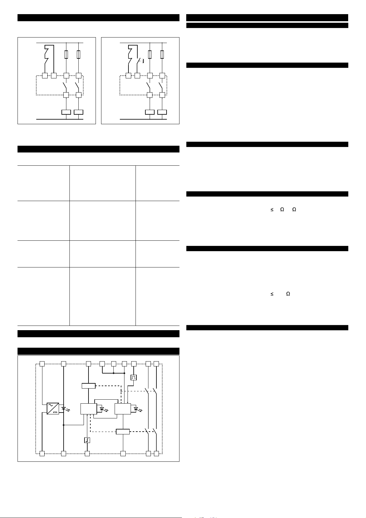
6 AUMENTO DO NÚMERO E CAPACIDADE DE CONTATO
Se necessário, é possível aumentar o número e a capacidade de carga dos contatos
de saída utilizando contatores externos com contatos de guia forçada
Circuito de feedback para contatores
externos com partida automática Circuito de feedback para contatores exter-
nos com partida manual ou monitorada
9 ESQUEMA INTERNO DE LIGAÇÃO E LAYOUT DOS TERMINAIS
7 FALHAS
10.1 Invólucro
Material:
Grau de proteção:
Dimensões (L x A x P):
Secção dos condutores:
Torque de aperto nos terminais:
Poliamida PA 6.6, V-0 (UL 94)
IP 40 (invólucro) IP 20 (terminais)
111,5 x 99,0 x 22,5 mm
0,2 ... 2,5 mm2
24 ... 12 AWG
0,5 ... 0,6 Nm
10.2 Informações Gerais
Nível SIL (SIL CL):
Nível de Performance (PL):
Categoria de segurança:
MTTFd (tempo médio para falha grave):
PFHd (probabilidade de falha grave por hora):
Tempo de missão ou intervalo de
verifi cação periódica:
Temperatura ambiente:
Vida mecânica:
Vida elétrica:
Grau de poluição:
Tensão de impulso Uimp:
Tensão de isolação Ui
Categoria de sobretensão:
Peso:
até SIL 3 conforme EN 62061
até PL e conforme EN ISO 13849-1
até categoria 4 conforme EN ISO 13849-1
218 anos
4,58 E-10
20 anos
-25 ... +55 °C
>10 milhões de ciclos de operações
>100.000 ciclos de operações
externo 3, interno 2
4 kV
250 V
II
0,3 kg
10.3 Alimentação
Tensão de alimentação nominal Un:
Ondulação residual máx. em cc:
Tolerância da tensão de alimentação Un:
Potência consumida em ca:
Potência consumida em cc:
12 Vcc
24 Vca/cc; 50...60 Hz
120 Vca; 50...60 Hz
230 Vca; 50...60 Hz
10%
±15% di Un
< 5 VA
< 2 W
10.4 Circuito de controle
Proteção contra curto circuito:
Tempo de operação do PTC:
Resistência por entrada:
Corrente por entrada:
Duração mín. do impluso de partida tMIN:
Tempo de disponibilidade tA:
Tempo de reação tR1:
Tempo de reação na deserginização tR:
Tempo de simultaneidade tC:
resistência PTC, Ih=0,5 A
intervenção > 100 ms, reset > 3 s
50 (15 )*
< 30 mA (70 mA)*
> 200 ms (100 ms)*
< 150 ms ( 220 ms)*
< 20 ms (15 ms)*
< 150 ms (50 ms)*
infi nito
10.5 Circuito de saída
Contatos de saída:
Tipo de contato:
Material do contato:
Tensão máx. de comutação:
Corrente máx. de comutação por cantato:
Corrente nominal térmica Ith:
Máx. somatória das correntes Σ Ith2:
Corrente mínima:
Resistência de contato:
Fusível de proteção externo:
Carga máx. comutável:
Categoria de utilização (EN 60947-5-1):
Categoria de utilização (UL 508):
2 contatos NA de segurança
guia forçada
liga de cobre banhada a ouro
230/240 Vca; 300 Vcc
6 A
6 A
36 A2
10 mA
100 m
4 A
1380 VA/W
AC15, Ue=230 V, Ie=3 A;
DC13, Ue=24 V, Ie=4 A (6 ciclos op./minuto)
C300
10.6 Conformidade com normas
Conformidade com as normas:
Conformidade com as diretivas:
Distância de isolação e escoamento conforme:
EN 60204-1, EN ISO 13855, EN 1037,
EN ISO 12100, EN ISO 13850, EN
60529, EN 61000-6-2, EN 61000-6-3,
EN 62326-1, EN 60664-1, EN 60947-1,
EN ISO 13849-1:2008, EN ISO 13849-
2:2012, EN 62061:2005 + EC: 2010 +
A1:2013, UL 508, CSA C22.2 n° 14-95
2006/95/CE, 2006/42/CE, 2004/108/CE
EN 60947-1
K3
K3
K4
K4
FF
N /-
L /+
S33 S34 13 23
14 24
K3
K3
K4
K4
FF
N /-
L /+
S33 S34 13 23
14 24
LED
PWR
L / +
N / -
LOGICA LOGICA
8 MANUTENÇÃO
Luzes LED Possível falha Ação recomendada
PWR
Desligado CH1
Desligado CH2
Desligado • Falha da fonte de alimentação
do módulo de segurança.
• Conexão elétrica errada.
• Cabos de alimentação cortados.
• Fusível externo danifi cado.
• Curto circuito entre os canais.
• Falha interna no módulo de
segurança.
Verifi que as conexões
e o fusível. Se a falha
persistir, substitua o
módulo.
PWR
Ligado CH1
Desligado CH2
Ligado • Conexão elétrica errada.
• Contatos do dispositivo de
parada de emergência colados
ou contatos do dispositivo de
monitoramento de porta ligados
em S21-S22.
• Contato do botão de partida
colados (partida monitorada).
• Falha interna no módulo de
segurança.
Verifi que a fi ação, o
botão de partida e
parada de emer-
gência/porta de
segurança. Se a falha
persistir, substitua o
módulo.
PWR
Ligado CH1
Ligado CH2
Desligado • Contatos do dispositivo de
parada de emergência colados
ou contatos do dispositivo de
monitoramento de porta ligados
em S11-S12.
• Falha interna no módulo de
segurança.
Verifi que a fi ação
e a parada de
emergência/porta de
segurança. Se a falha
persistir, substitua o
módulo. .
PWR
Ligado CH1
Desligado CH2
Desligado • Conexão elétrica errada.
• Contator externo colado ou
falha no módulo de expansão.
• Cabos de alimentação cortados.
• Circuito aberto em um ou
ambos contatos de parada de
emergência do dispositivo de
segurança de monitoramento
de porta.
• Ausência de sinal (impulso de
partida) para partida manual ou
monitorada ou o fechamento de
ambos os canais para partida
automática.
• Falha interna no módulo de
segurança.
Verifi que a fi ação, os
canais e a confi gura-
ção inicial. Se a falha
persistir, substitua o
módulo.
Este módulo não necessita de manutenção.
* version CS AR-08•U12

A1
13
23
A2
14
24
S11
S12
S31
S33
S21
S22
S35
S34
PWR
CH1
CH2
S52
24 VDC
+
-
OSSD
S52 S33
S21 S22 S35 S34
S12
CS AR-08
A1
A2
24 VDC
+
-
S52 S33
S21 S22 S35 S34
S12
CS AR-08
A1
A2
OSSD1 OSSD2
S33
S21 S22 S35 S34
CS AR-08
A2
S31
S11
S12
A1
L / +
N / -
S33
S21 S22 S35 S34
CS AR-08
A2
S31
S11
S12
A1
N / -
L / +
2015 Copyright Pizzato Elettrica - Translation of the original instructions
ZE_FOG46A15-IE_PTB
To contact our technical offi ce: phone ++39.0424.470.930 - fax ++39.0424.470.955 - e-mail tech@pizzato.com
36063 MAROSTICA (VI) ITALY
Via Torino, 1
Phone +39.0424.470.930
Fax +39.0424.470.955
E-mail info@pizzato.com
www.pizzato.com
4 APPLICATION EXAMPLES
Monitored start confi guration
A1/A2
S33/S34 (START)
13/14, 23/24
tAtR1
tR1
tAtR
tMIN tA
S11/S12 (+/S12)
S21/S22 (+/S52)
Automatic start confi guration
A1/A2
S11/S12 (+/S12)
S21/S22 (+/S52)
13/14, 23/24
tCtAtR1
tR1 tCtAtR
tA
Manual start confi guration
A1/A2
S33/S34 (START)
13/14, 23/24
tAtR1
tR1 tAtR
tMIN
S11/S12 (+/S12)
S21/S22 (+/S52)
Note:
The confi gurations with one channel are obtained taking into consideration only the
S11/S12 (+/S12) input. In this case it is necessary to consider the tR1 time referred
to S11/S12 (+/S12) input, the tR time referred to the supply, the tA time referred
to S11/S12 (+/S12) input and to the start, and the tMIN time referred to the start.
Legend:
tMIN: Min. period of start impulse
tC: Simultaneity time
tA: Availability time
tR1: Reaction time
tR: Reaction time in absence of
power supply
Automatic start
As regards the indicated
diagrams, in order to
activate the module with
the automatic start, it is
necessary to short the
start button between S33
and S34 terminals. S34 S34
Monitored start
As regards the indicated
diagrams, in order to
activate the module with
the monitored start, it is
necessary to remove the
connection between S22
and S35 terminals.
S21
S22
S21
S22 S35
Gate monitoring and safety magnetic sensors.
The safety module can
control both emergency
stop circuits, gate
monitoring circuits or
safety magnetic sensors.
Replace the emergency
stop contacts with
switches contacts or with
the sensors contacts.
Emergency stop
Input Manual start confi guration
1 channel - SIL 1 - PL c - Cat. 2 2 channels - SIL 3 - PL e - Cat. 4
Solid state output circuit (e.g. light curtain)
Input Manual start confi guration
1 channel - SIL 1 - PL c - Cat. 2 2 channels - SIL 3 - PL e - Cat. 4
2 WARNING
3 TERMINALS LAYOUT
1 FUNCTION
- The installation and the wiring should be carried out only by professional workers.
- Before any kind of operation, it should be checked that this device is disconnect from power supply.
- The safety module should be installed and fi xed in the DIN rail, inside an electric panel.
- Verify that the safety module is used inside the operating ranges.
- Check that the safety module does not show evidence of damage suffered during the transport or
incorrect storage.
- Install a 4 A fuse in series to each output contact to avoid the contacts stick.
- It is advisable to power the safety module with a separate source respect to the power supply of the
machine and keep separate the wiring connections of the module from the wiring of main power line.
- Verify the correct operation of the module following the instructions of the operation diagrams.
- If expansion modules or external contactors are installed, check that the contacts are forced guided
type and install in feedback function one NC contact for each device.
- The safety category, according to EN ISO 13849-1, achieved by the system including the safety
module, depends also on the external circuit.
- The improper use of the safety module can lead to hazardous situation.
- In case of low demand applications (e.g. emergency stop) verify module safety function at least
once a year.
- In the risk analysis it must be considered that in manual start mode a sticky start button could lead
to immediate module activation.
- Muting or suspending of the safety function input is not provided.
- In case of fault, the module enters the safe state and the safety output is de-energized.
• Safety function: at the opening of at least one channel the safety relay must open its output contacts
within defi ned reaction time. The safety outputs are activated only when CH1 and CH2 circuits are
coherently closed and after the START signal is activated.
• Input circuit with 1 or 2 channels.
• Up to safety category 4 (EN ISO 13849-1), SIL 3 (EN 62061), PL e (EN ISO 13849-1).
• The safety function SIL3 / PL e can only be obtained with the two redundant inputs confi guration.
• Supply voltage 24 Vac/dc, 120 Vac, 230 Vac.
• Choice between automatic start, manual start or monitored start.
• With reference to the operating mode “automatic”, consider the requirement 1.2.3 of the Machinery
Directive 2006/42/EC: “ For machinery functioning in automatic mode, the starting of the machinery,
restarting after a stoppage, or change in operating conditions may be possible without intervention,
provided this does not lead to a hazardous situation.”.
• Connection of the input channels to opposite potentials.
• Connectable to solid state outputs with self testing between channels (OSSD) or to magnetic
safety sensor;
• Function of detection of short circuit in the control devices through safety system with self-monitoring
and redundancy method.
• Output contacts: 2 NO safety contacts.
• LED indicating the switching state of the channels 1, 2 and of the supply voltage.
5 OPERATION DIAGRAMS
art. CS AR-08••••

DISCLAIMER:
Technical modifi cations and errors reserved. The data in this sheet have been carefully checked and represent typical
values of series production.
The descriptions of the device and its applications, its usage contexts, the details on external controls, and the installation
and operating information are given to the best of our knowledge. This does not mean, however, that any legal responsibility
or other claims under liability law that extend beyond the “General Sales Terms” stated in the Pizzato Elettrica General
Catalogue may be derived. The user is not absolved of his obligation to examine our information, recommendations, and
relevant technical regulations before using Pizzato products for his own purposes. This document is a translation of the
original instructions. In case of discrepancy between the present sheet and the original copy, the Italian version shall prevail.
K1
K2
A1
S11
S12
S33
S31
S34
13
23
A2
S21
S35
S22
14
24
LED
CH1
LED
CH2
S52
EC DECLARATION OF CONFORMITY
The undersigned, representing the following manufacturer :Pizzato Elettrica s.r.l. , Via Torino, 1 - 36063 Marostica
(VI) - Italy
herewith declares that the product is in conformity with the Machinery directive 2006/42/CE. The complete EC
Declaration of Conformity is available on
www.pizzato.com
Ing. Pizzato Giuseppe
At the end of service life product must be disposed of properly
2015 Copyright Pizzato Elettrica - Translation of the original instructions
9 INTERNAL WIRING DIAGRAM AND TERMINALS LAYOUT
7 FAILURE
10.1 Housing
Material:
Protection degree:
Dimensions (L x H x S):
Cross section of the conductors:
Terminals driving torque:
Polyamide PA 6.6 class V0 (UL94)
IP 40 (housing), IP 20 (terminal board)
111,5 x 99,0 x 22,5 mm
0,2 ... 2,5 mm2
24 ... 12 AWG
0,5 ... 0,6 Nm
10.2 General data
SIL level (SIL CL):
Performance Level (PL):
Safety category:
MTTFd:
PFHd:
Mission Time:
Ambient temperature:
Mechanical endurance:
Electrical endurance:
Pollution degree:
Rated impulse withstand voltage Uimp:
Rated insulation voltage Ui:
Over-voltage category:
Weight:
up to SIL 3 according to EN 62061
up to PL e according to EN ISO 13849-1
up to category 4 according to EN ISO 13849-1
218 years
4,58 E-10
20 years
-25°C ... +55°C
>10 millions of operations
>100.000 operations
outside 3, inside 2
4 kV
250 V
II
0,3 kg
10.3 Supply
Rated operating voltage Un:
Max residual ripple in DC:
Supply voltage tolerance:
Rated power consumption AC:
Rated power consumption DC::
12 Vdc
24 Vac/dc; 50...60 Hz
120 Vac; 50...60 Hz
230 Vac; 50...60 Hz
10%
±15% of Un
< 5 VA
< 2 W
10.4 Control circuit
Protection against short circuits:
Availability time of PTC:
Max input resistance :
Input current:
Min. period of start impulse tMIN:
Availability time tA:
Reaction time tR1:
Reaction time on de-energisation tR:
Simultaneity time tC:
resistance PTC, Ih=0,5 A
intervention > 100 ms, reset > 3 s
50 (15 )*
< 30 mA (70 mA)*
> 200 ms (100 ms)*
< 150 ms ( 220 ms)*
< 20 ms (15 ms)*
< 150 ms (50 ms)*
infi nite
10.5 Output circuit
Output contacts:
Contacts type:
Contacts material:
Max. switching voltage:
Max. switching current per contact:
Conventional free air thermal current Ith:
Max currents sum Σ Ith2:
Min. current:
Contacts resistance :
Protection fuse outside:
Max. switching capacity:
Utilization category (EN 60947-5-1):
Utilization category (UL508):
2 NO safety contacts,
Forcibly guided contacts
Silver alloy, gold plated
230/240 Vac; 300 Vdc
6 A
6 A
36 A2
10 mA
100 m
4 A
1380 VA/W
AC15, Ue=230 V, Ie=3 A;
DC13, Ue=24 V, Ie=4 A (6 operations/minute)
C300
10.6 Conforms to the standards
Conforms to the standards
:
Conforms to the directives
:
Clearance and creepage distances in
accordance with:
EN 60204-1, EN ISO 13855, EN 1037,
EN ISO 12100, EN ISO 13850, EN
60529, EN 61000-6-2, EN 61000-6-3,
EN 62326-1, EN 60664-1, EN 60947-1,
EN ISO 13849-1:2008, EN ISO 13849-
2:2012, EN 62061:2005 + EC: 2010 +
A1:2013, UL 508, CSA C22.2 n° 14-95
2006/95/EC, 2006/42/EC, 2004/108/EC
EN 60947-1
K3
K3
K4
K4
FF
N /-
L /+
S33 S34 13 23
14 24
K3
K3
K4
K4
FF
N /-
L /+
S33 S34 13 23
14 24
6 INCREASE OF THE NUMBERAND THE LOADINGCAPACITY OF THECONTACTS 10 TECHNICAL DATA
If necessary it is possible to increase the number and the loading capacity of the
output contacts by using external contactors with forcibly guided contacts.
Feedback circuit for external contactors
with automatic start wiring Feedback circuit for external contactors
with manual or monitored start wiring
LED
PWR
L / +
N / -
LOGIC
CIRCUIT
LOGIC
CIRCUIT
Led lights Possible failure Recommended
actions
PWR
Off CH1
Off CH2
Off • Lack of power supply to safety
module.
• Wrong connection.
• PWR wires cut down.
• Breakdown of external fuses.
• Short circuit between channels.
• Failure of safety module.
Verify the connec-
tions and check
the fuse. If the fault
persists, replace the
module.
PWR
On CH1
Off CH2
On • Wrong connection.
• Stick contacts of emergency
stop or the device of the safety
gate monitoring connected to
S21-S22.
• Stick contacts of the start button
(monitored start).
• Failure of safety module.
Check the wiring,
the start button and
the emergency stop/
safety gate. If the fault
persists, replace the
module.
PWR
On CH1
On CH2
Off • Stick contacts on the emergency
stop or on the device of the
s a fe t y g a t e m o n i t o r i n g
connected to S11-S12.
• Failure of safety module.
Check the wiring and
the emergency stop/
safety gate. If the fault
persists, replace the
module.
PWR
On CH1
Off CH2
Off • Wrong connection.
• External contactors stick or
failure in the expansion module.
• Input wires cut down.
• Open circuit of one or both
contacts of emergency stop of
safety gate monitoring.
• Missing automatic cycle for
manual or monitored start
(start impulse) or closure
of both channels for the
automatic start.
• Failure of safety module;
Check the wiring,
the channels and the
start confi guration.
If the fault persists,
replace the module.
The module is maintenance free.
8 MAINTENANCE
* version CS AR-08•U12
Table of contents
Languages:
Other Pizzato Elettrica Relay manuals
Popular Relay manuals by other brands

Omron
Omron G3PE Series manual

Siemens
Siemens SIRIUS 3UG4651 operating instructions

Moeller
Moeller Z 1-75 installation instructions

Coelbo
Coelbo SWITCHMATIC 2T Advanced Settings

Honeywell
Honeywell NOTIFIER FRM-1 Installation and maintenance instructions

Ei Electronics
Ei Electronics RadioLINK Relay Module Ei428 instruction manual