9
I-BEAM RF POWER SUPPLY MANUAL Chapter 1: Getting Started
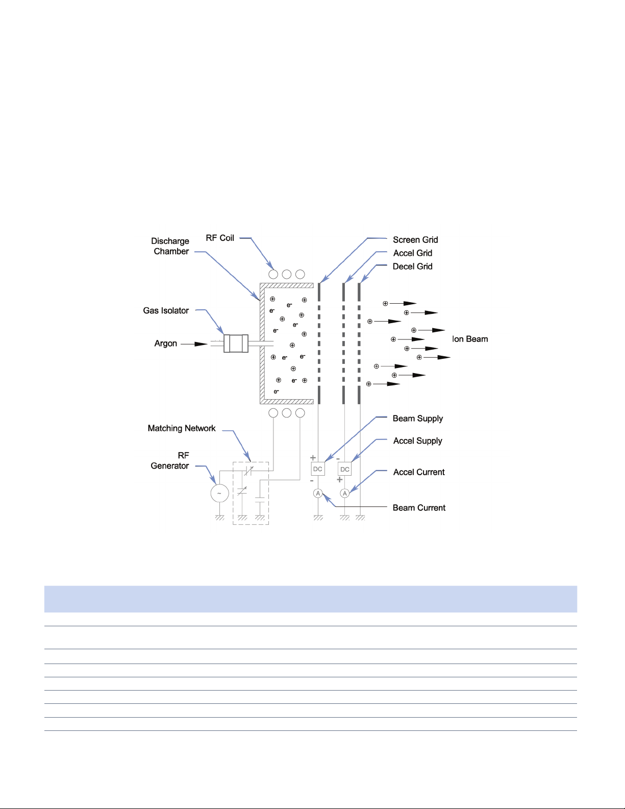
The grids, which control the ion optics, will come in
dierent shapes, sizes and materials. They can be
at (i.e. graphite) or dished (i.e. molybdenum) to
promote beam shape and trajectories. The inner
most grid is called the screen grid (biased positive)
and the middle grid is called the accelerator (biased
negative). Most grid assemblies will have 3 grids
where the decelerator will act as a shield to the other
two grids and capture process material coming back
to the source. Additional information about the grid
operation and design can be found in the Ion Beam RF
Sources Manual.
A neutralizer is placed downstream from the source
where it emits electrons to balance the number
of positive ions which leave the source. The RFN
operates in a similar fashion to the source as it
requires process gas, has an RF antenna and its own
matching network. Please refer to its manual for a
detailed description of its operation and additional
information.
The RFN needs to be placed so that its electrons can
couple (or “see”) the ion beam. It is very important
that these electrons have a close (about 150 mm),
unobstructed path to the beam to ensure stable,
noise free operation. The RFN should also be located
away from strong magnets or shielded from magnetic
elds using 400 series stainless steel. A common
challenge will be to protect the RFN from process
material that can coat its keeper - but allow for
electrons to couple.
Electrons from the neutralizer do not recombine
with source ions, rather they provide space-charge-
neutralization for the downstream plasma. Under
normal operation, the neutralizer will emit between
125% to 200% of the measured beam current. In this
fashion substrates or targets downstream will not
suer damage due to arcing or surface charging.
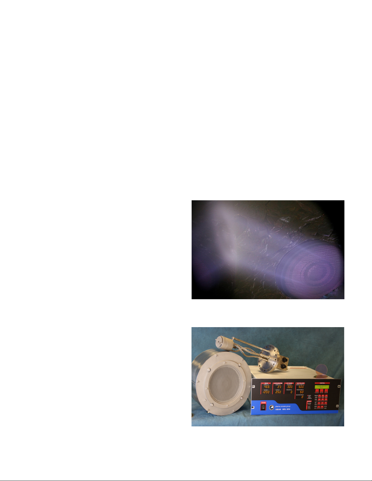
Typical grids before assembly.
Place the RFN in close proximity to the ion beam.
The RFN will emit more electrons than ions from
the source.