TEXIO PFR-100M250 Manual

B71-0479-01
INSTRUCTION MANUAL
WIDE RANGE DC POWER SUPPLY
PFR-100 SERIES
PFR-100L50
PFR-100M250
PFR-100L50G
PFR-100M250G

■About Brands and Trademarks
“TEXIO” is the product brand name of our industrial electronic devices.
All company names and product names mentioned in this manual are the
trademark or the registered trademark of each company or group in each
country and region.
■About the Instruction Manual
Permission from the copyright holder is needed to reprint the contents of this
manual, in whole or in part. Be aware that the product specifications and the
contents of this manual are subject to change for the purpose of improvement.

CONTENTS
USING THE PRODUCT SAFELY ···························Ⅰ-Ⅳ
1. GETTING STARTED ...................................................1
1-1. PFR-100 Series Overview...............................................1
1-1-1. Series lineup .....................................................................................1
1-1-2. Main Features...................................................................................1
1-1-3. Accessories.......................................................................................2
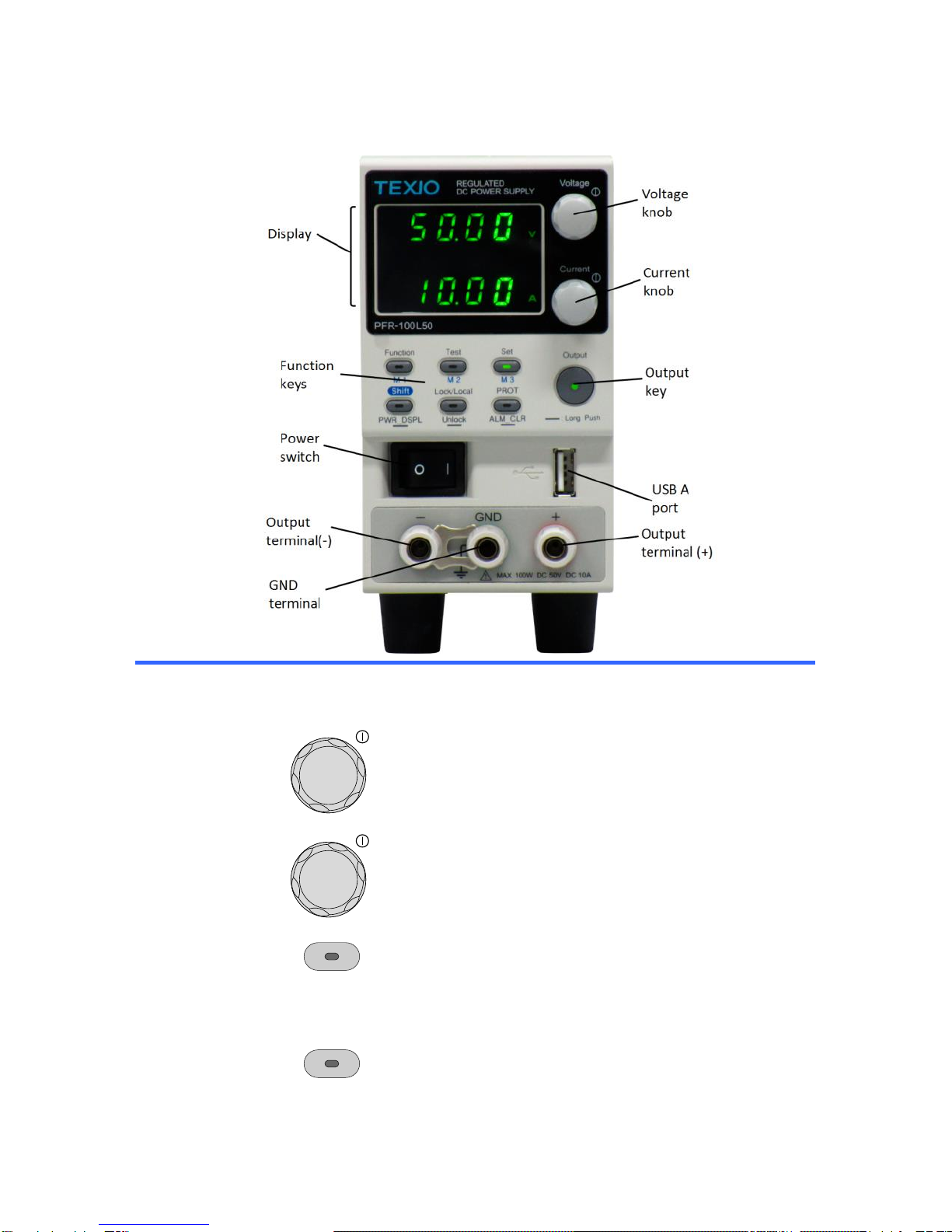
1-2. Appearance....................................................................3
1-2-1. Front Panel........................................................................................3
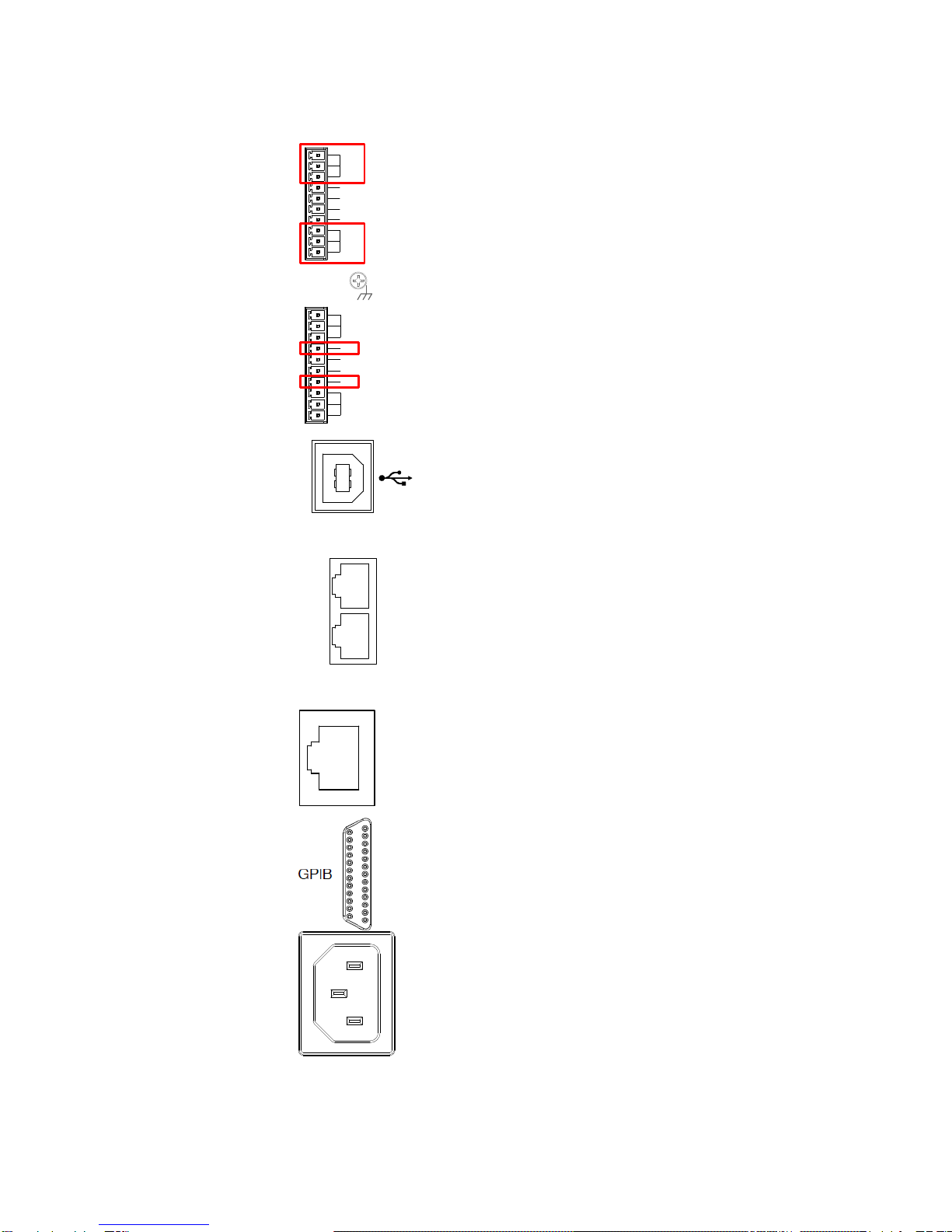
1-2-2. Rear Panel........................................................................................5
1-3. Theory of Operation .......................................................7
1-3-1. Operating Area Description...............................................................7
1-3-2. CC and CV Mode..............................................................................8
1-3-3. Slew Rate..........................................................................................9
1-3-4. Bleeder Control.................................................................................9
1-3-5. Sink Current Table ..........................................................................10
1-3-6. Alarms.............................................................................................11
1-3-7. Considerations................................................................................11
1-3-8. Grounding .......................................................................................13
2. OPERATION.............................................................15
2-1. Set Up ......................................................................... 15
2-1-1. Power up.........................................................................................15
2-1-2. Wire Gauge Considerations............................................................15
2-1-3. The Rear Panel Output Terminal ....................................................16
2-1-4. The Front Panel Output Terminal....................................................17
2-1-5. Using the Output Terminal Cover....................................................18
2-1-6. Using the Rack Mount Kit................................................................19
2-1-7. How to Use the Instrument..............................................................19
2-1-8. Reset to Factory Default Settings....................................................20
2-1-9. View System Version and Build Date..............................................21
2-2. Basic Operation............................................................ 23
2-2-1. Setting OVP/OCP/UVL Levels ........................................................23
2-2-2. Set to CV Mode...............................................................................25
2-2-3. Set to CC Mode...............................................................................27
2-2-4. Display Modes.................................................................................29
2-2-5. Panel Lock ......................................................................................29
2-2-6. Preset Memory................................................................................30
2-2-7. Remote Sensing..............................................................................31
2-3. Test Script.................................................................... 33
2-3-1. Test Script File Format....................................................................33
2-3-2. Test Script Settings.........................................................................33
2-3-3. Setting the Test Script.....................................................................33
2-3-4. Load Test Script from USB drive.....................................................34
2-3-5. Run Test Script ...............................................................................35
2-3-6. Export Test Script to USB ...............................................................36
2-3-7. Remove Test Script.........................................................................37
2-3-8. Checking the Available Memory......................................................37

2-3-9. Data structure of the Test Script......................................................37
2-3-10. Setting values of the test Script.....................................................38
3. CONFIGURATION.....................................................40
3-1. Configuration Table ...................................................... 40
3-2. Normal Function Settings ............................................. 43
3-3. USB / GP-IB Settings ................................................... 45
3-4. LAN Settings ................................................................ 45
3-5. UART Settings ............................................................. 46
3-6. System Settings ........................................................... 46
3-7. Power On Configuration Settings .................................. 47
3-8. Special Function........................................................... 47
3-9. Setting Normal Function Settings.................................. 48
3-10. Setting Power On Configuration Settings .................... 49
4. ANALOG CONTROL .................................................50
4-1. Analog Remote Control Overview.................................. 50
4-1-1. Analog Control Connector (J1) Overview........................................50
4-1-2. External Voltage Control of Voltage Output.....................................52
4-1-3. External Voltage Control of Current Output.....................................54
4-1-4. External Resistance Control of Voltage Output...............................55
4-1-5. External Resistance Control of Current Output...............................57
4-1-6. External Control of Output...............................................................58
4-1-7. External control of Shutdown ..........................................................60
4-1-8. External control of Alarm Clear .......................................................61
4-2. Remote Monitoring ....................................................... 62
4-2-1. External Voltage and Current Monitoring ........................................62
4-2-2. External Operation and Status Monitoring.......................................63
5. Communication Interface ........................................66
5-1. USB Interface............................................................... 66
5-1-1. USB Remote Interface ....................................................................66
5-1-2. USB-CDC Remote Control Function Check....................................67
5-2. GPIB Interface ............................................................. 67
5-2-1. GPIB Remote Interface...................................................................67
5-2-2. GPIB Function Check......................................................................68
5-3. LAN Interface ............................................................... 71
5-3-1. Web Server Configuration...............................................................71
5-3-2. Web Server Remote Control Function Check .................................72
5-3-3. Socket Server Configuration ...........................................................73
5-3-4. Socket Server Function Check........................................................73
5-4. Serial Interface............................................................. 77
5-4-1. UART Remote Interface..................................................................77
5-4-2. UART Function Check.....................................................................78
5-5. Multidrop Interface ....................................................... 79
5-5-1. Multiple Unit Connection .................................................................79
5-5-1-1. Multi-Drop mode.......................................................................79
5-5-1-2. Multi-Drop mode Function Check.............................................81
6. FAQ .........................................................................83

7. APPENDIX ...............................................................84
7-1. PFR-100 Factory Default Settings................................. 84
7-2. Error Messages & Messages ........................................ 85
7-3. LED ASCII Table Character Set .................................... 86
7-4. Test Script Error Code .................................................. 86
8. Specification list .....................................................87
8-1. Rating.......................................................................... 87
8-1-1. Output .............................................................................................87
8-1-2. Constant Voltage Mode...................................................................87
8-1-3. Constant Current Mode...................................................................87
8-1-4. Protection Function.........................................................................88
8-1-5. Analog Programming and Monitoring..............................................88
8-1-6. Front Panel......................................................................................89
8-1-7. Programming and Measurement (Control)......................................89
8-1-8. Input Characteristics........................................................................90
8-1-9. Interface Capabilities.......................................................................90
8-1-10. Environment Conditions................................................................90
8-1-11. General Specifications ..................................................................91
8-2. PFR-100 Dimensions.................................................... 92

I
USING THE PRODUCT SAFELY
■Preface
To use the product safely, read instruction manual to the end. Before using this
product, understand how to correctly use it. If you read the manuals but you do
not understand how to use it, ask us or your local dealer. After you read the
manuals, save it so that you can read it anytime as required.
■Pictorial indication
The manuals and product show the warning and caution items required to
safely use the product. The following pictorial indication is provided.
Pictorial
indication
Some part of this product or the manuals may show this
pictorial indication. In this case, if the product is incorrectly
used in that part, a serious danger may be brought about
on the user's body or the product. To use the part with this
pictorial indication, be sure to refer to the manuals.
WARNING
!
If you use the product, ignoring this indication, you may get
killed or seriously injured. This indication shows that the
warning item to avoid the danger is provided.
CAUTION
!
If you incorrectly use the product, ignoring this indication,
you may get slightly injured or the product may be
damaged. This indication shows that the caution item to
avoid the danger is provided.
Please be informed that we are not responsible for any damages to the user or
to the third person, arising from malfunctions or other failures due to wrong use
of the product or incorrect operation, except such responsibility for damages as
required by law.

II
USING THE PRODUCT SAFELY
WARNING
!
CAUTION
!
■Do not remove the product's covers and panels
Never remove the product's covers and panels for any purpose.
Otherwise, the user's electric shock or fire may be incurred.
■Warning on using the product
Warning items given below are to avoid danger to user's body and life and
avoid the damage or deterioration of the product. Use the product, observing
the following warning and caution items.
■Warning items on power supply
●Power supply voltage
The rated power supply voltages of the product are 100VAC. The rated power
supply voltage for each product should be confirmed by reading the label
attached on the back of the product or by the “rated” column shown in the
instruction manual. The specification of power cord attached to the products
is rated to 125VAC for all products which are designed to be used in the
areas where commercial power supply voltage is not higher than 125VAC.
Accordingly, you must change the power cord if you want to use the product
at the power supply voltage higher than 125VAC. If you use the product
without changing power cord to 250VAC rated one, electric shock or fire may
be caused. When you used the product equipped with power supply voltage
switching system, please refer to the corresponding chapter in the instruction
manuals of each product.
●Power cord
(IMPORTANT) The attached power cord set can be used for
this device only.
If the attached power cord is damaged, stop using the product and call us or
your local dealer. If the power cord is used without the damage being
removed, an electric shock or fire may be caused.
●Protective fuse
If an input protective fuse is blown, the product does not operate. For a
product with external fuse holder, the fuse may be replaced. As for how to
replace the fuse, refer to the corresponding chapter in the instruction
manual. If no fuse replacement procedures are indicated, the user is not
permitted to replace it. In such case, keep the case closed and consult us or
your local dealer. If the fuse is incorrectly replaced, a fire may occur.

III
USING THE PRODUCT SAFELY
■Warning item on Grounding
If the product has the GND terminal on the front or rear panel surface, be sure
to ground the product to safely use it.
■Warnings on Installation environment
●Operating temperature and humidity
Use the product within the operating temperature indicated in the “rating”
temperature column. If the product is used with the vents of the product
blocked or in high ambient temperatures, a fire may occur. Use the product
within the operating humidity indicated in the “rating” humidity column.
Watch out for condensation by a sharp humidity change such as transfer to a
room with a different humidity. Also, do not operate the product with wet
hands. Otherwise, an electric shock or fire may occur.
●Use in gas
Use in and around a place where an inflammable or explosive gas or steam is
generated or stored may result in an explosion and fire. Do not operate the
product in such an environment. Also, use in and around a place where a
corrosive gas is generated or spreading causes a serious damage to the
product. Do not operate the product in such an environment.
●Installation place
Do not insert metal and inflammable materials into the product from its vent
and spill water on it. Otherwise, electric shock or fire may occur.
■Do not let foreign matter in
Do not insert metal and inflammable materials into the product from its vent
and spill water on it. Otherwise, electric shock or fire may occur.
■Warning item on abnormality while in use
If smoke or fire is generated from the product while in use, stop using the
product, turn off the switch, and remove the power cord plug from the outlet.
After confirming that no other devices catch fire, ask us or your local dealer.

IV
USING THE PRODUCT SAFELY
■Input / Output terminals
Maximum input to terminal is specified to prevent the product from being
damaged. Do not supply input, exceeding the specifications that are indicated
in the "Rating" column in the instruction manual of the product. Also, do not
supply power to the output terminals from the outside. Otherwise, a product
failure is caused.
■Calibration
Although the performance and specifications of the product are checked under
strict quality control during shipment from the factory, they may be deviated
more or less by deterioration of parts due to their aging or others.
It is recommended to periodically calibrate the product so that it is used with its
performance and specifications stable. For consultation about the product
calibration, ask us or your local dealer.
■Daily Maintenance
When you clean off the dirt of the product covers, panels, and knobs, avoid
solvents such as thinner and benzene. Otherwise, the paint may peel off or
resin surface may be affected. To wipe off the covers, panels, and knobs, use
a soft cloth with neutral detergent in it.
During cleaning, be careful that water, detergents, or other foreign matters do
not get into the product.
If a liquid or metal gets into the product, an electric shock and fire are caused.
During cleaning, remove the power cord plug from the outlet.
Use the product correctly and safely, observing the above warning and caution
items. Because the instruction manual indicates caution items even in
individual items, observe those caution items to correctly use the product.
If you have questions or comments about the manuals, ask us or E-Mail us.

1
1. GETTING STARTED
This chapter describes the power supply in a nutshell, including its main features
and front / rear panel introduction. After going through the overview, please read
the theory of operation to become familiar with the operating modes, protection
modes and other safety considerations.
1-1. PFR-100 Series Overview
1-1-1. Series lineup
The PFR-100 series consists of 2 models, covering a number of different current,
voltage and power capacities. The G model supports LAN and GPIB.
Model name
Voltage
Current
Rated Power
GP-IB/LAN
PFR-100L50
0~50.00V
0~10.00A
100W
-
PFR-100L50G
○
PFR-100M250
0~250.0V
0~2.000A
100W
-
PFR-100M250G
○
1-1-2. Main Features
Performance
Variable voltage and current combinations with 5 times of
coverage ratio of its range within the rated power.
Constant voltage / constant current with automatic
crossover.
Active Power Factor correction.
Universal Input Voltage 80~265VAC, continuous
operation.
Natural convection cooling(Fanless).
Features
Preset memory function (3sets).
Output ON/OFF delay function.
CV, CC priority start function. (prevents overshoot with
output ON)
Adjustable voltage and current slew rates.
Bleeder circuit ON/OFF setting. (to prevent
over-discharging of betteries)
OVP, OCP, AC FAIL and OHP protection.
Supports test scripts.
Web server monitoring and control. (The function is
activated when connecting to LAN Interface)
Analog monitor output.
Remote sensing to compensate for voltage drop in load
leads.
Built-in front panel and rear panel output terminal.
Interface
Built-in USB and RS-232C/RS-485 interface.
External analog control function.
LAN and GP-IB interface. (G model)

2
1-1-3. Accessories
Standard
Accessories
Part number
Description
CD ROM
User manual, Programming manual,
USB Driver, Sample test scripts
Power cord
Depends on Regional and Type.
GTL-134
Test leads for rear panel, 1.2m, 10A, 16AWG
PFR-100L
PFR-001
PFR-100LAccessory Kit
Output terminal cover x 1
Output terminal x 1
Socket x 1
Protection cover x 2
Short Bar x 1
GTL-104A
Test leads for PFR-100L, 1m, 10A
PFR-100M
PFR-002
PFR-100MAccessory Kit
Output terminal cover x 1
Output terminal x 1
Socket x 1
Protection cover x 2
Short Wire x 1)
GTL-105A
Test leads for PFR-100M, 1m, 3A
Option
Part number
Description
GRA-431-J-100
Rack mount adapter (JIS) with AC 100V
GRA-431-J-200
Rack mount adapter (JIS) with AC 200V
GRA-431-E-100
Rack mount adapter (EIA) with AC 100V
GRA-431-E-200
Rack mount adapter (EIA) with AC 200V
GTL-258
GP-IB Cable for PFR Only
GTL-259
RS-232C cable with DB9 connector
GTL-260
RS-485 cable with DB9 connector
GTL-261
RS-485 used master cable (gray plug)
Terminator
GTL-262
slave cable (black plug)
GTL-246
USB cable (USB 2.0 A - B)
Driver
Name
Description
texio_cdc*.inf
USB driver

3
1-2. Appearance
1-2-1. Front Panel
Function keys
The Function keys along with the Output key will light up when a
key is active.
Voltage Knob
Voltage
Used to set the voltage value or select a parameter
number in the Function settings.
Current Knob
Current
Used to set the current value or change the value of
a Function parameter.
Function Key
M1 Key
Function
M1
Used to configure the various functions.
(+Shift) Used to recall the M1 setup.
(+Shift and hold) Used to save the current setup to
M1.
Test Key
M2 Key
Test
M2
Used to run customized scripts for testing.
(+Shift) Used to recall the M2 setup.
(+Shift and hold) Used to save the current setup to
M2.

4
Set Key
M3 Key
Set
M3
Used to set and confirm the output voltage and
output current.
(+Shift) Used to recall the M3 setup.
(+Shift and hold) Used to save the current setup to
M3.
Shift Key
PWR_DSPL
Key
PWR_DSPL
Shift
Used to enable the functions that are written in blue
characters below certain buttons.
(Long push) Displays the output power on the
voltage meter or current meter. Press the Voltage
knob for V/W, Press the Current knob for A/W.
Lock/Local
Key
Unlock Key
Lock/Local
Unlock
Used to lock all front panel buttons other than the
Output Button or it switches to local mode.
(Long push) Used to unlock the front panel buttons.
PROT Key
ALM_CLR
Key
PROT
ALM_CLR
Used to set and display OVP, OCP and UVL.
(Long push) Used to release protection functions
that have been activated.
Output Key
Output
Used turn the output on/off.
Power switch
Used turn the power on/off.
USB A port
USB A port for data transfer, loading test scripts etc.
Output
terminal
PFR-100M
250V/2A/100W
PFR-100L
50V/10A/100W
Display
indicators
VSR
Lights up when CV Slew Rate Priority is enabled.
C V
Lights in green during constant voltage mode.
RMT
Lights in green during remote control.
ALM
Lights in red when a protection function has been
activated.
DLY
The Output On/Off Delay indicator LED.
C C
Lights in green during constant current mode.

5
ISR
Lights up when CC Slew Rate Priority is enabled.
ERR
Lights in red when an error has occurred.
LAN
Lights up when the LAN remote connection is
established.
M1
Lights in green when the memory value are being
recalled or saved.
M2
Lights in green when the memory value are being
recalled or saved.
M3
Lights in green when the memory value are being
recalled or saved.
V or W
Display Voltage or Watt unit.
RUN
Lights up when a Test Script has been activated.
A or W
Display Current or Watt unit.
Upper numeric
Displays the voltage or the parameter number of a
Function parameter.
Lower numeric
Displays the current or the value of a Function
parameter.
1-2-2. Rear Panel
Analog Control
Connector (J1)
Standard 26 pin MIL connector
(OMRON XG4 IDC plug).
The analog control connector is used to
monitor current and voltage output,
machine status (OVP, OCP, OHP etc.), and
for analog control of the current and
voltage output.
Use an OMRON XG5 IDC socket as the
mating socket.

6
Output Terminals
It uses a 10 pin connector and a plug for the output and sense
terminal connectors. The plug is MC420-38110Z made by
DECA SwitchLab.
+V
-V
+S
-S
N.C.
N.C.
Positive (+) and negative (-) output terminals.
Chassis ground
+V
-V
+S
-S
N.C.
N.C.
Sense (-) and Sense (+) terminals.
USB B port
The USB B port is used for remote control.
Remote-OUT port
OUT
IN
RS232
/RS485
RJ-45 connectorthat is used to daisy chain
power supplies with the Remote-IN port to
form a communication bus.
Remote-IN port
Two different types of cables can be used for
RS232 or RS485-based remote control.
GTL-259: RS232 cable with DB9 connector
kit.
GTL-260: RS485 cable with DB9 connector
kit.
LAN (Ethernet)
port
LAN
The ethernet port is used for remote control
and digital monitoring from a PC. (G model
only)
GPIB port
GPIB connector for units equipped with IEEE
programming option. . (G model only)
Line Voltage Input
Voltage Input: 100~240 VAC
(automatically switchable)
Line frequency: 50Hz / 60Hz

7
1-3. Theory of Operation
The theory of operation chapter describes the basic principles of operation,
protection modes and important considerations that must be taken into account
before use.
1-3-1. Operating Area Description
Background
The PFR-100 power supplies are regulated DC power supplies
with a high voltage and current output. These operate in CC or
CV mode within a wide operating range limited only by the
output power.
The operating area of each power supply is determined by the
rated output power as well as the voltage and current rating.
Below is a comparison of the operating areas of each power
supply.
Voltage (V)
Current (A)
250
100W Rated power
50
0.4 2
PFR-100M250 Operating Area
Voltage (V)
Current (A)
50
100W Rated power
10
2 10
PFR-100L50 Operating Area
When the power supply is configured so that the total output
(current x voltage output) is less than the rated power output,
the power supply functions as a typical constant current,
constant voltage power supply.
If however, the power supply is configured such that the total
output (current x voltage output) exceeds the rated power
output, the effective output is actually limited to the power limit
of the unit. In this case the output current and voltage then
depend purely on the load value.

8
1-3-2. CC and CV Mode
CC and CV mode
Description
When the power supply is operating in constant current
mode (CC) a constant current will be supplied to the load.
When in constant current mode the voltage output can
vary, whilst the current remains constant. When the load
resistance increases to the point where the current limit
(ISET) can no longer be sustained the power supply
switches to CV mode. The point where the power supply
switches modes is the crossover point.
When the power supply is operating in CV mode, a
constant voltage will be supplied to the load, whilst the
current will vary as the load varies. At the point that the
load resistance is too low to maintain a constant voltage,
the power supply will switch to CC mode and maintain the
set current limit.
The conditions that determine whether the power supply
operates in CC or CV mode depends on the set current
(ISET), the set voltage(VSET), the load resistance (RL) and
the critical resistance (RC). The critical resistance is
determined by VSET/ISET. The power supply will operate in
CV mode when the load resistance is greater than the
critical resistance. This means that the voltage output will
be equal to the VSET voltage but the current will be less
than ISET. If the load resistance is reduced to the point that
the current output reaches the ISET level, the power supply
switches to CC mode.
Conversely the power supply will operate in CC mode
when the load resistance is less than the critical
resistance. In CC mode the current output is equal to ISET
and the voltage output is less than VSET
RL=RC
RL<RC
VSET
CV
CC
V
I
RL>RCCrossover
point
ISET

9
1-3-3. Slew Rate
Theory
The PFR-100 has selectable slew rates for CC and CV
mode. This gives the PFR-100 power supply the ability to
limit the current/voltage draw of the power supply. Slew
rate settings are divided into High Speed Priority and Slew
Rate Priority. High Speed Priority mode disables slew rate
settings for CC or CV mode. Slew Rate Priority mode
allows for user adjustable slew rates for CC or CV mode.
The rising and falling slew rate can be set independently.
High Speed
Priority mode Slew rate: Enabled
1-3-4. Bleeder Control
Background
The PFR-100 DC power supplies employ the bleeder
circuit in parallel with the output terminals.
PFR-100
Load
Bleeder
circuit
The bleeder circuit is designed to dissipate the power from
the power supply filter capacitors when power is turned off
and the load is disconnected. Without the bleeder circuit,
power may remain charged on the filter capacitors for
some time and be potentially hazardous.
In addition, the bleeder circuit also allow for smoother
voltage regulation of the power supply as the bleeder
circuit acts as a minimum voltage load.
The bleeder circuit can be turned on or off using the
configuration settings
Asetting of AUTO to turn on the bleeder when output is on,
the output will turn off the bleeder when off.

10
Note
By default the bleeder circuit is on. For battery charging
applications, be sure to turn the bleeder circuit off as the
bleed resistor can discharge the connected battery when
the unit is off.
1-3-5. Sink Current Table
Background
Sink current (reference value) from an external voltage
source according to the bleeder circuit setting.
PFR-100M250
Vout
Bleeder ON
Bleeder OFF
Sink Current
(V)
(A)
(mA)
25
0.135
0.001
50
0.119
0.007
75
0.103
0.014
100
0.087
0.022
125
0.071
0.032
150
0.055
0.034
175
0.039
0.043
200
0.034
0.051
225
0.031
0.067
250
0.028
0.086
PFR-100L50
Vout
Bleeder ON
Bleeder OFF
Sink Current
(V)
(A)
(mA)
5
0.746
0.006
10
0.658
0.009
15
0.570
0.013
20
0.482
0.017
25
0.375
0.026
30
0.310
0.038
35
0.257
0.038
40
0.236
0.048
45
0.218
0.074
50
0.200
0.200

11
1-3-6. Alarms
The PFR-100 power supplies have a number of protection features. When one of
the protection alarms are set, the ALM icon on the display will be lit. For details on
how to set the protection modes, please see page 23.
OVP
Over voltage protection (OVP) prevents a high voltage
from damaging the load. This alarm can be set by the user.
OCP
Over current protection prevents high current from
damaging the load. This alarm can be set by the user.
OPP
Over power protection prevents abnormally use from
damaging the PFR-100.
When the output powers is over 103W, the alarm LED
flashes. After a little time, OPP will be triggered and turn off
output.
UVL
Under voltage limit. This function sets a minimum voltage
setting level for the output. It can be set by the user.
OHP
Over temperature protection protects the instrument from
overheating.(Typ. 90°C)
AC FAIL
AC Fail. This alarm function is activated when a low AC
input is detected. (Typ.80V)
SENSE ALARM1
This alarm function is activated when real output voltage is
larger than sense output voltage.
Vo_real > Vo_sense + 1.5V for PFR-100L50
Vo_real > Vo_sense + 2.5V for PFR-100M250
SENSE ALARM2
This alarm function is activated when sense output voltage
is larger than real output voltage.
Vo_sense > Vo_real + 1V
Shutdown
Force Shutdown is not activated as a result of the
PFR-100 series detecting an error. It is a function that is
used to turn the output off through the application of a
signal from the rear-panel analog control connector when
an abnormal condition occurs.
Alarm output
Alarms are output via the analog control connector. The
alarm output is an isolated open-collector photo coupler
output.
1-3-7. Considerations
The following situations should be taken into consideration when using the power
supply.
Inrush current
When the power supply switch is first turned on, an inrush
current is generated. Ensure there is enough power
available for the power supply when first turned on,
especially if a number of units are turned on at the same
time.
Caution
Cycling the power on and off quickly can cause the inrush
current limiting circuit to fail as well as reduce the working
life of the input fuse and power switch.
Pulsed or Peaked
loads
When the load has current peaks or is pulsed, it is possible
for the maximum current to exceed the mean current
This manual suits for next models
3
Table of contents
Other TEXIO Power Supply manuals

TEXIO
TEXIO PBW Series User manual

TEXIO
TEXIO PSW Series Owner's manual

TEXIO
TEXIO PSW Series User manual

TEXIO
TEXIO PSF-1200L User manual

TEXIO
TEXIO PR-A Series User manual

TEXIO
TEXIO PS-A Series User manual

TEXIO
TEXIO PSF-400H User manual

TEXIO
TEXIO PU6-200 User manual

TEXIO
TEXIO PU Series User manual

TEXIO
TEXIO PD18-10AD User manual
Popular Power Supply manuals by other brands

Xantrex
Xantrex RS232-XHR operating manual

Vertiv
Vertiv NetSure 8200 Series installation manual

ETI
ETI AD-1 instruction manual

UNI
UNI ACP Series Technical and Operational Manual

American Magnetics
American Magnetics 601 Installation, operation and maintenance instructions

MSTRONIC
MSTRONIC MSR-1231 user guide