Plastimo ECHOFISH 820 User manual

Installation
& operation manual
Dual-frequency
fishfinder
ECHOFISH 820
Other languages
available on CD

Echofish 820 –Installation & Operation manual
2
Introduction
Thank you for choosing our Echofish 820 fishfinder and welcome to
the innovations of 3/$67,02. We have been committed
to fishfinder R&D activities and our products have been reputed for
their cutting-edge technologies and reliable performances.
Your fishfinder is a high-quality sonar designed for both professional
and novice fisherman in a variety of water areas and conditions. This
product benefits from 1 year warranty against any damages induced
by non-human factors. Damages which could happen out-of-
warranty will be handled with reasonable charges based on concrete
situations. For details regarding maintenance service, please refer to
the warranty section at the end of this manual.
To familiarize yourself better with the product’s operations and, in
order maximize its use, we invite you to read this manual carefully.
Please read the transducer and sonar unit mounting step by step to
benefit from the optimum performances of your instrument. An in-
correct installation, especially the transducer one, could make your
sonar unit works abnormally or not work at all.
For any possible problems you may face during the operation, please
refer to the Trouble Shooting section.
Except as expressly provided herein, no part
of
this manual may
be copied, reproduced, republished,
transmitted
or
distributed
for
any
purpose, without
prior
written consent of 3/$67,02
3/$67,02 may find it necessary to change or end RXUSROLFLHV
regulations and special offers at any time. We
reVHUYHWKH
right to change or improve its products and to make FKDQJHVLQ
the
content without obligation
to
notify
any
perVRQRU
organization.
For current updates or any other information, please visit our web-
site or contact us at:
www.SODVWLPR.com
PLASTIMO – Lorient-France
7HO
FRQWDFW#SODVWLPRFRP
ZZZSODVWLPRFRP

Echofish 820 –Installation & Operation manual
3
Table of contents
Understanding sonar ........................................................... 4
No-skipping detection ......................................................... 5
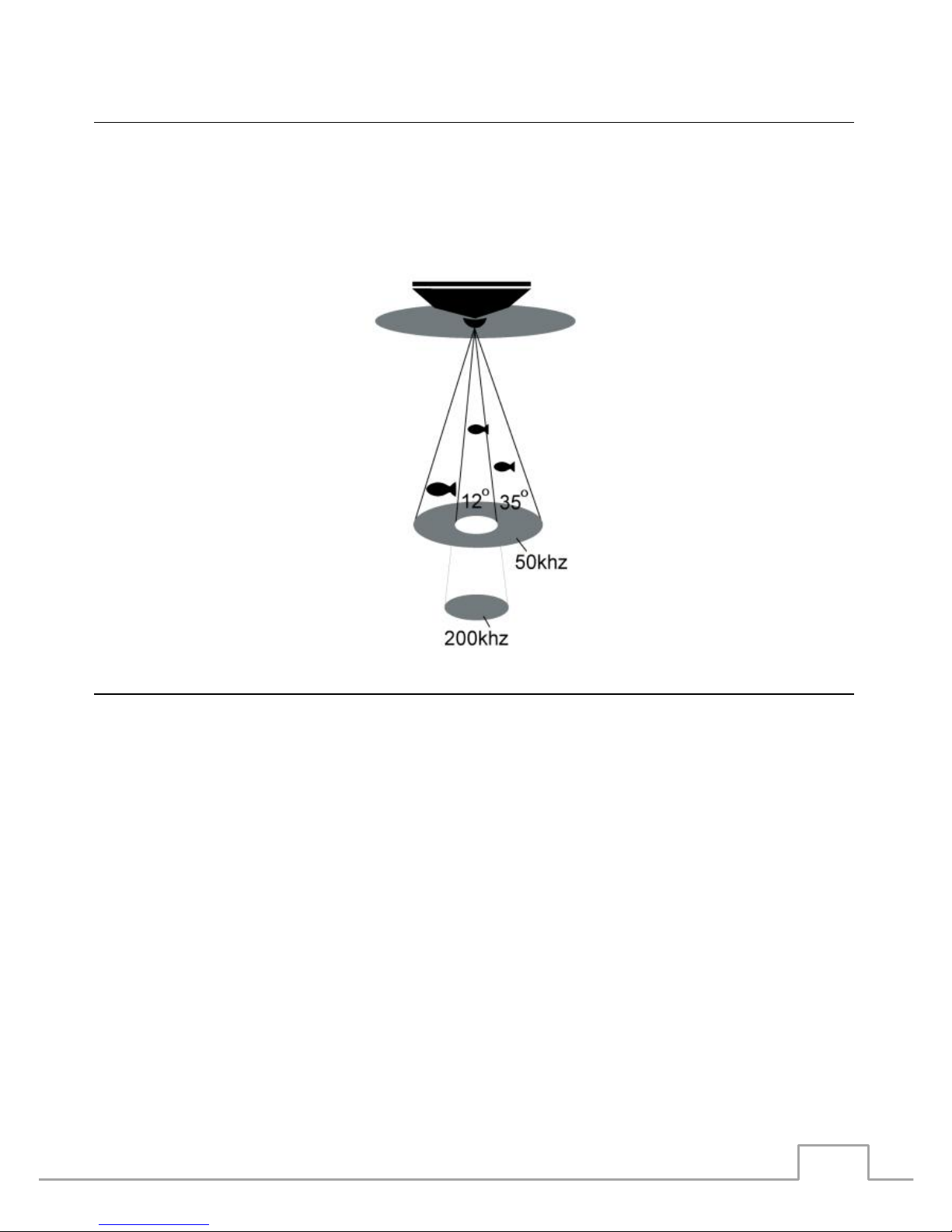
Dual Beam Sonar................................................................. 6
What’s in the box ? ............................................................. 6
Transducer installation
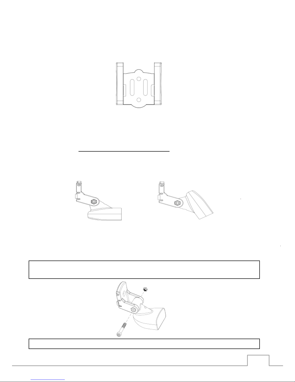
1. Transom installation ................................................ 7
2. Shoot-thru-hull transducer installation....................... 12
Sonar unit installation ......................................................... 15
Operation Instruction
Understanding the Fishfinder screen ............................... 18
Real time sonar window................................................. 19
Keyboard instruction ..................................................... 20
Data interface .............................................................. 21
Menu Operations
Chart speed .......................................................... 22
Noise Filter ........................................................... 22
Color line.............................................................. 24
Sensitivity ............................................................ 25
Fish ID. Sens ........................................................ 25
Water type .......................................................... 26
Frequency ........................................................... 27
TCG Control .......................................................... 28
Depth Range......................................................... 29
Zoom Range ......................................................... 30
Backlight .............................................................. 31
Echostyle.............................................................. 32
Keel offset ............................................................ 33
Beeper ................................................................. 34
Simulator ............................................................. 35
Languages ............................................................ 36
System info .......................................................... 36
Load default.......................................................... 37
Temperature units ................................................. 37
Depth units........................................................... 38
Fish ID alarm ........................................................ 38
Shallow ................................................................ 39
Battery................................................................. 40
Trouble Shooting................................................................. 41
Maintenance........................................................................ 43
Storage ............................................................................... 44
Guarantee Conditions ......................................................... 44
Specifications and features................................................. 45

Echofish 820 –Installation & Operation manual
4
UNDERSTANDING SONAR
If you are familiar with the manipulation of a sonar, please
skip to the next section. However, if you have never owned
any sonar fishfinder yet, this section will teach you the basic
theory about sonar.
Based on the sonar technology, the Echofish 820 fish-
finder can detect
the
underwater conditions, including
fish presence or bottom structure. The transducer sends a
sound
wave signal into the water in
a
cone shape. At the
source,
the
wave is narrow; however as
it
penetrates
deeper, the
sound
wave spreads forming a
cone
(i.e
flashlight). The sound wave bounces back to the
transduc-
er
when it strikes any object. The object can be a fish, the
structure, the bottom or any other object with a different
density from the water.
The transducer amplifies the return signal and sends it
back to
the fishfinder
. By measuring the time between the
sound wave transmission and its bounce, the fishfinder can
calculate the distance thanks to the inner microproces-
sor. T h e
fishfinder
displays the information on the screen
for your interpretation.

Echofish 820 –Installation & Operation manual
5
No Skipping Detection
Your fishfinder integrates a high detecting technology. Real-
ly precise, it enables a “No-skipping detection”.
When the sonar works, it continually samples the echo at
same interval (for your fishfinder, it is 0.06 ms). T he
continuous signals
form
different sampling
points. The
shorter the
distance between
2 sampling points is, the more
precise your f ishf ind er is. Even small size objects can be
detected.

Echofish 820 –Installation & Operation manual
6
Dual beam sonar
The Echofish 820 adopts a 200/50 kHz Dual beam sonar
system. With the Dual beam sonar setting, you can use the
narrow 12°beam to penetrate the deep bottom while you are
still being able to use the wide 35° beam for a wide detection.
What’s in the box ?
Please do not start the
installation of your fishfinder be-
fore
reading the
instructions carefully. This manual con-
tains critical information to install your fishfinder correctly
.
F
or any
problems
you m a y f a c e
during the installa-
tion, please contact your local dealer for assistance.
Before a n y i n s t a l l a t i o n , please check
the p
acking list
below and make sure you are not missing any items:

Echofish 820 –Installation & Operation manual
7
A- Display unit
B- Bracket
C- Transducer
D- Pivot
E- Template
F-
Locking bolt
G- Pivotbolt
H- Pivot nut
I- 4x15mm screws
J- 3x20mm screws
Transducer installation
1. Transom installation
1.1 Select the mounting location
When choosing the transducer mounting location, do not
forget to consider the flowing as well. The sonar
transmis-
sion
/
reception
can be
affected severely
in turbulent waters.
Never mount the
transducer
behind rows of rivet, water in-
take, discharge port, propeller area, etc. These areas can
create turbulences when the boat moves a t a
high
speed.
1.2 Mark the location and drill the mounting holes
Make sure the boat is flush and parallel with the water sur-
face.
Hold the template against the transom of the boat, mark

Echofish 820 –Installation & Operation manual
8
Wrong
Right
two holes in both slots. The center of both holes must be
parallel with water surface. Make sure the distance between
the bottom of the template and the lower edge of the tran-
som is about
0~5mm.
Using a 5/32” bit, drill 2 holes of 1” (25mm) deep approx-
imately at the marked location. Be careful not to drill deeper
than 1”.
1.3 Assemble the transducer
Slightly spread the pivot and match the
transducer
to the pi-
vot. The
toothed
surface makes them not separate easily.
Put the locking nut into the slot of the pivot, insert the pivot
bolt and hand-tighten.
Note: Do not overtighten the pivot-bolt with an Allen wrench; oth-
erwise you will not be able to adjust the angle of the transducer.
Note: Do not push the pivot into the bracket.

Echofish 820 –Installation & Operation manual
9
1.4 Transducer installation
a- Apply marine sealant to the 4 x 15mm screws and the
two holes on transom. Hold the bracket against the transom
again, slightly tightens the template by two 4 x 15mm
screws.
Note: Do not overtighten; otherwise you will not be able to adjust
the transducer.
b- Adjust the template to make it roughly vertical to the wa-
ter
surface. T
ighten the two screws with an Allen wrench.
c- Press the pivot into the bracket and rotate the transducer
to make it parallel with the water surface.
Note: The pivot matches
the
transducer by ratchets. Incline is 12
degree. In some
situations,
you may find it
impossible
to
adjust
the
transducer
completely
parallel
with the water
surface.
In this
situation
a slight
incline
(1~5degree)
is acceptable.
1.5 Routing the cable
You can choose to route the transducer through or over the
transom. If through the transom, please follow the next
steps:
a- Hold one cable clamp at
approximately
1/4
distance
f
rom the top of transom to the transducer. Mark the posi-
tion with a pencil. Using a 1/8” bit, drill two holes o f
approximately 3/8”
(10mm) deep.

Echofish 820 –Installation & Operation manual
10
b- Apply some marine sealant to the hole and tighten
the
cable clamp with two screws.
c- If more than one cable clamp is needed, repeat step a)
and b).
Note: make sure the cable between the transducer and the first
clamp is not tightened. Otherwise the transducer cable can be easily
damaged when adjusting the transducer. To avoid this situation,
please rotate the transducer to the utmost position before tightening
the first cable clamp.
d) When routing the transducer cable to the sonar unit, avoid
enwinding the transducer cable with other electrical wires or
some electrical
devices
that may
cause
interference.
1.6 Initial installation test
To get the best transducer installation, we suggest you to
test the initial installation and to adjust the transducer ac-
cording to the test outcome.
Before testing, please make sure the installation is finished: the
transducer cable must be correctly connected to t
he
dis-
play unit. Make sure the distance between the transducer
and bottom is not beyond the depth of your fishfinder’s ca-
pacity.
a- Power up the display unit and check whether there is sonar
information on the screen. If so, it means the display unit is
correctly connected to the transducer. If not, please check
the connection between the display unit and the transducer.
The template touchs the
transducer

Echofish 820 –Installation & Operation manual
11
b- First, run your boat at a low speed. See the sonar infor-
mation on the screen. If the screen comes out normal, then
speed up your boat. Always observe the display unit during
the course. If the signal is lost or abnormal at a certain
speed, note the speed.
c- Adjust the
transducer
in a small scope and run the boat at
the noted speed. Observe the display unit. If the screen is
normal, go to the next step. If not, please adjust the trans-
ducer until it comes out normal. If by any means, a normal
sonar display can not be obtained, then it is necessary for
you to relocate the position of the transducer.
1.7 Final installation
a- Make sure the transducer can be completely immersed into
water and adjust the location of the template on the tran-
som. This will
make
the
transducer’s transmission
/
reception
being
affected
by the whirlpool at the smallest extent when
the boat runs at a high speed.
b- As soon as you believe you have found the best mounting
location of the transducer, release the pivot from the tem-
plate, then mark the third hold with a pencil.
c- Using a 5/32” bit, drill a hole of approximately 1” (25mm)
deep at the marked position.
d- Apply marine sealant in the three holes and hold the
template
against the transom. When you are sure that the in-
stallation is completely in line with the mounting location,
tighten the three screws with an Allen wrench.

Echofish 820 –Installation & Operation manual
12
e- Press the pivot into the template.
2. Shoot-thru-hull installation
The previous installation t y p e ( t r a n s o m ) is the
most widely used method. However, in
some situations, you
can also
use the
Shoot-thru-hull transducer
installation, which
is more convenient and faster. However, considering the
material of the boat and any
possible trapped
air
bubbles
in
the material, sonar
signals
will be
slightly reduced
when
pass-
ing through
the boat hull.
2.1 Preparation
The boat hull should be of a single layer
construction,
since the
sonar
signal can not pass through air.
Note: The areas which are chosen to mount the transducer should be
free from turbulent water. Any ribs, strakes and any other protrusions
that may create turbulences should be avoided.
With a
double-hulled
boat, you can choose the
shoot-thru-hull
installation type only if the flotation material (such as ply-
wood, balsa, wood or foam) has b e en removed from the
chosen area.
Outer
Epoxy
Resin
Inner hull
Flotation material hull

Echofish 820 –Installation & Operation manual
13
Warning: contact your boat dealer to get the full specifications of
your boat. Never try to remove any material from the inner hull be-
fore you completely know about the its composition
Choose an appropriate position in the inner hull. Remove
the
inner fiberglass layer as well as the flotation material.
Epoxy the transducer to the outer layer of fiberglass; press
the transducer with a slight twisting motion to purge any
trapped air from underneath.
After the epoxy cures for 24hours, (make sure the epoxy is
solidified) the remaining space can be filled in with resin.
The installation of the transducer is then finished. With the
shoot-thru-hull installation, the transducer will not be ad-
justed as soon as it is fixed. So, testing before final
in-
stallation is
necessary.
2.2 Finding a better mounting location
a- Fill the hull with water to submerge the transducer.
b- In the sump of the boat, place the transducer at the iden-
tified mounting position, face down. You can use heavy ob-
jects to keep the transducer in position.
c- Turn the display unit on, run the boat where water depth
is about 20 feet to test whether the sonar display is normal
(if needed, please adjust the sensitivity and depth range). If
not, check the connection between the display unit and the
transducer.
d- Run the boat at various speeds to see h ow t he d i s-
p l ay u n i t b e h av e s . If one of the following phenomena
appears: sonar strength obviously decreasing, loss of signal
,
bottom missing, then note the speed and choose another
location
for the transducer. Repeat the operation until you get the best
mounting
location.

Echofish 820 –Installation & Operation manual
14
2.3 Permanent Shoot-Thru-Hull installation
a- Make sure the surface of the chosen location is
clear, dry
and free of any oil. Sand the mounting surface of the trans-
ducer with 100 grit sandpaper until it looks very clean and
flat.
b- Wipe off the sand debris on mounting surface with a
piece of cloth. Clean the mounting surface of hull and
transducer
with
rubbing alcohol.
c- Get a quantity of epoxy and hardener and mix them as
described in the epoxy manual
d- When the epoxy looks unworkable (about 20 minutes are
needed from the beginning you mixing them), make sure
there are no air bubbles in the epoxy layer, then spread a
thin layer of epoxy
on
the surface of transducer, a compa-
rably thick layer to the surface of sand area on the hull.
e- Press the transducer into the epoxy of the sanding area
on the hull with a slight twisting motion, forcing any air
bubbles out from underneath. Make sure the face of the
transducer will be parallel with the hull after you finish the
entire above job.
Warning: do not bump the transducer while the epoxy is wet. It will
take about 24hours for the epoxy to cure completely.

Echofish 820 –Installation & Operation manual
15
Sonar unit installation
1. Finding a mounting location
When starting the installation of your fishfinder, the following
should be considered:
a- Location has to be convenient to get the best viewing an-
gle.
b- Leave enough space to tilt &
twist the bracket.
c- Leave enough behind the display unit to route
the
cable.
d) The mounting surface must be flat to ge a stable in-
stallation. Otherwise it will be very hard to fix the lower
twist base. An instable installation may damage your fish-
finder when the
boat
encounters severe wave shocks.

Echofish 820 –Installation & Operation manual
16
2. Installating the display unit
a-Assemble the bracket : hold the bracket to match the so-
nar unit control head
b- Assemble the locking knob
c- Fix the f
ishfinder
on the
installation
surface.
3. Connecting the power cable to the boat
Your fishfinder includes a 1.5 m long power cable. Connect
the
power
cable to the transducer and battery correctly.
Warning: some boats may have a 24 or 36 volt electric system. The
Echofish 600 accepts a 12 volt electric system. Any damages from
the surplus power will void your warranty.
Control head
Bracket
Locking knob

Echofish 820 –Installation & Operation manual
17
Warning : we can not be responsible for over-voltage or over-current
failures. To avoid possible failures, we suggest you to use a 3Amp
fuse

Echofish 820 –Installation & Operation manual
18
Operation Instructions
1. Understanding the Fishfinder screen
This chart shows all the information your fishfinder can display
during the operation. The upcoming sonar information will
first appear in the Real Time Sonar window, and then scrolls
across the screen from right to left. So, what you see on the
screen
(fish
symbols, f
ish arches, bottom shape, etc) is
formed by the sonar history. The black line at the top of the
screen represents the water surface. You can also read the
following information: water depth, water temperature and
real time battery voltage.
By moving the transducer slowly at a steady speed, you can
see the bottom shape at the bottom of the screen.

Echofish 820 –Installation & Operation manual
19
2. Real Time Sonar Window
The plot on the screen demonstrates the sonar history. Con-
sidering the boat and targets that continually move, the in-
formation displayed on the screen only shows the detected
target time segment.
You can imagine dividing the screen into many parallel
“bands” at vertical direction. Each “band” represents the sig-
nals received by the sonar unit at a particular time. The clos-
er the position of right side “band” is, the latest signal it
represents.
The Real Time Sonar Window shows the instant time seg-
ment when targets are detected. With the Real Time Sonar
window, you can right side instant sonar returns observe the
fastest updating which will show you the instant underwater
information, including depth, bottom, structure, and fish be-
ing detected.

Echofish 820 –Installation & Operation manual
20
3. Keyboard instruction
The fishfinder sounds a tone when you press the key. This
means the unit did accepted a command.
Menu key
The MENU key is used to enter a menu setting and to
n a v i g a t e
between the menus.
Ent Key
The Ent key is used to confirm a setting.
Zoom Key
The zoom key is used to enter into zooming setting.
Backlight Key
The BACKLIGHT key is used to increase or decrease light-
ness of the backlight.
Table of contents
Languages:
Other Plastimo Fish Finder manuals