Platinum Curve Stairlift User manual

1
Platinum Curve Stairlift
Installation Manual
THIS GUIDE IS COMPANY CONFIDENTIAL.
PLEASE RETAIN THIS GUIDE.
THIS GUIDE IS NOT TO BE LEFT WITH THE CUSTOMER.
Exclusively Curved

2
Contents Page
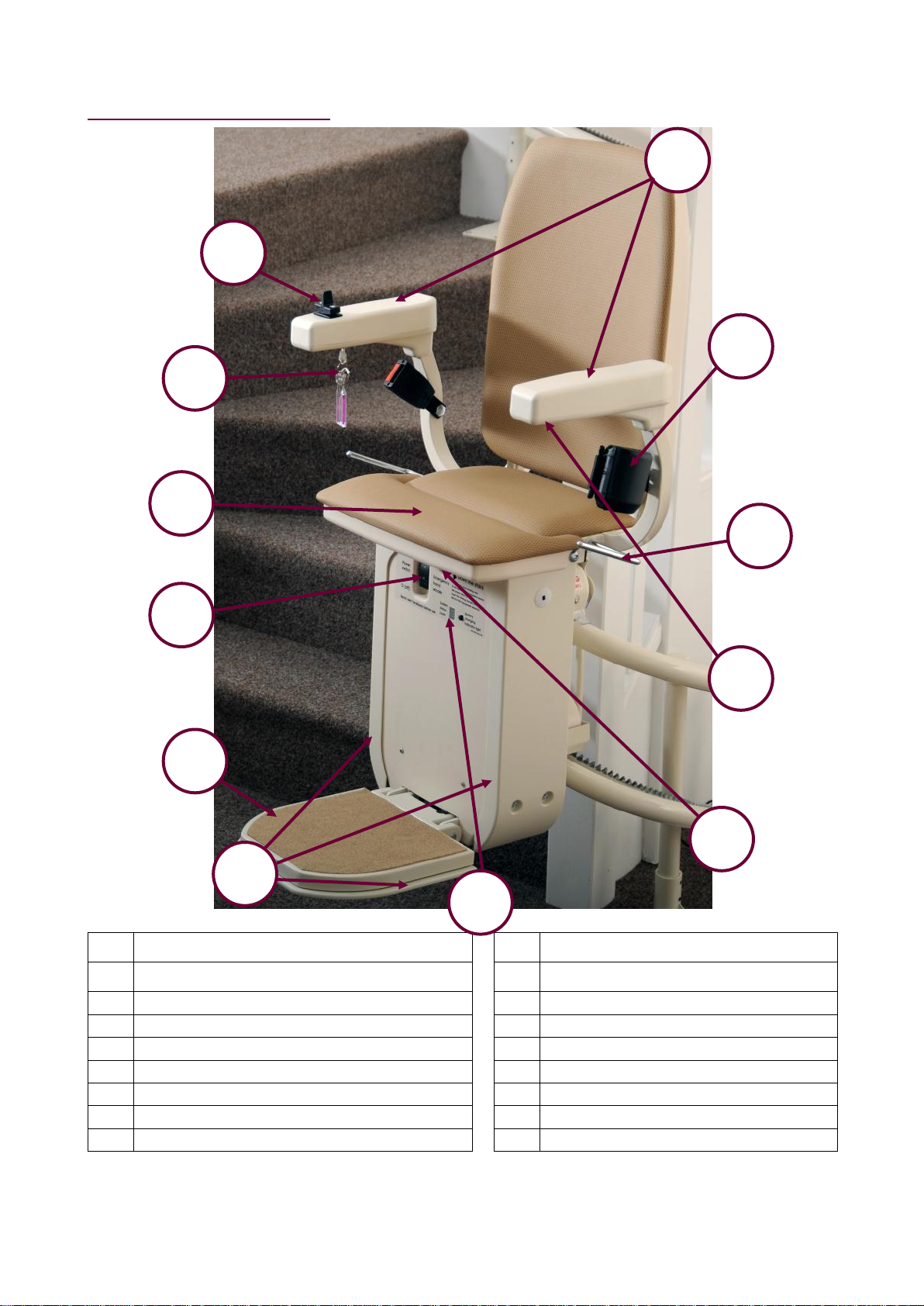
Stairlift Discription ………………………………………………………………………
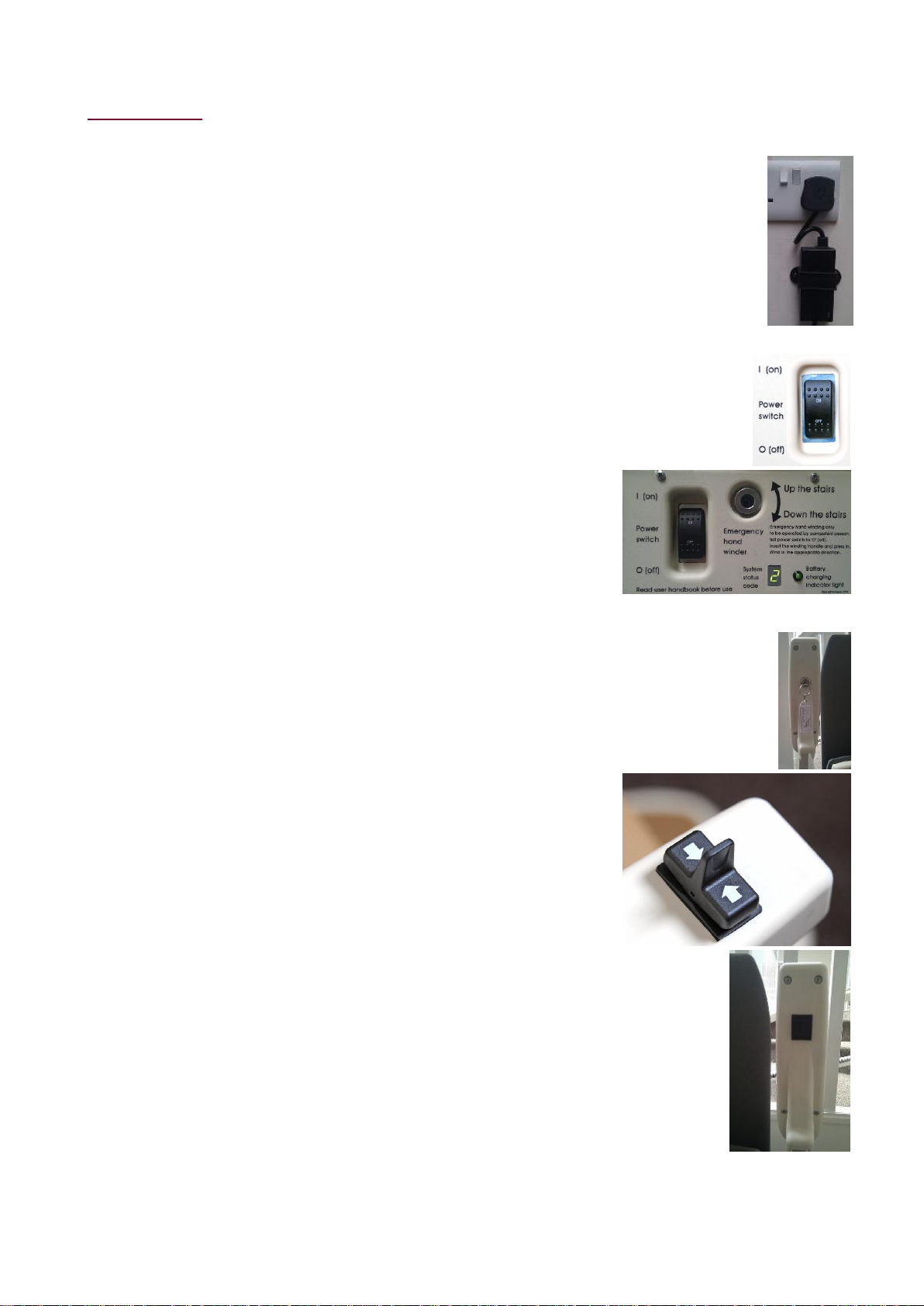
Controls ……………………………………………………………………………….………………………………………………………………..
Swivel Seat ……………………………………………………………….……………………………………………………………………..
Charging Points ………………………..…………………………………………………………………………………………………………….
Remote Controls ………………..…………………………………………………………………………………………………………………….
Kitting List …………………………………………....................................................................
Required Installation Equipment …………………………....................................................
Installing the Stairlift ……………………………………….....................................................
Installation Drawing ………………………………………………………….........................................................................................
Assembling the Rail …………………………………………………....................................................................................................
Fixing the Rail Assembly in Place ………………………………………………………………………………………………………………..
Fitting the Carriage to the Rail ………………………………………………………………..
Fitting the Batterys …………………………………………………………………………………………………………........................
Fitting the Combined End Stops/Charging Ramps …………………………………………………………………………………………..
Charge Circuit ……………………………………………………………………………………………………………………………………...
Intemediate Charge Point …………………………………...........................................................................................................
Fitting the Chair to Carriage ………………………………………………………………………………………………………………..
Chair and Carriage Electrical Connections ……………………………………………………………………………………………………..
Manual Carriage …………………………………………….…………………………………………………………………………….
Powered Footrest Carriage………………………………………………………………………………………...................................
Test Running Stairlift Unladen and Unprogrammed …………………………………………...
Programming Half and Full Speed ………………………………………………………………..
Installing Remote Controls ……………………………………………...........................................................................................................
Test Running the Stairlift Fully Laden and Programmed .……………………………………
Final Checks ……………………………………………….……………………………………
Contract/Installation drawing ……………………………………………….........................................................................................
Electrical, Battery and Operational Tests ……………………………………………………………………………………………………..
Certificate for Test and Examination After Installation …………………………………………………………………………………………..
Instructing the User ……………………………………………………………………………..
Paperwork …………………………………………………………………………………………...
Test Certificate ……………………………………………………………………………………………………………………………………...
User Guide ……………………………………………………………………………………………………………………………………...
Offset Footrest Option ……………………………………………………………………………...
Connection Diagram ……………………………………………………………………………..
Technical Information ……………………………………………………………………………..
Weight limits ……………………………………………………………………………………………………………………………………...
Operating Periods………………………………………………………………………………………………………….......................................
Handwinding the Stairlift …………………………………………………………………………………………………………………………..
Diagnostic codes…………………………………………………………………………………….
Mains Power, Battery Power and Power Cuts ……………………………………………………………………………………………………..
Servicing …………………………………………………………………………………………..
4
5
6
7
7
8
9
11
11
12
14
15
16
18
19
20
21
22
22
22
23
24
26
28
29
29
29
30
31
32
32
32
33
34
35
35
35
35
36
38
39

3
About this Manual
Description of this manual
This manual is intended to show you how to install a Platinum Curve
stairlift.
This manual contains detailed instructions about:
Intended Audience and their Required Knowledge
Typical Kitting List of Parts in a Platinum Curve stairlift
Required Installation Equipment you will need to install a stairlift
Health and Safety Guidance
Installing the Stairlift
Testing the Stairlift
Troubleshooting
Technical Information and System Status Codes
Instructing the User how to Use the Product
Paperwork
Quick Reference Guide
You should also have a User Guide to refer to –you must give this to the
resident when the installation is completed.
Intended Audience
This manual has been written to be used by specialist trained stairlift
installers.
The information in this guide assumes that you have already completed
specialist training on how to install a Platinum Curve stairlift and you have
perfomed an installation before, either at a customers dwelling or as part of
a training course.
This manual is not intended as a training guide.
This manual is not intended to show an unskilled person how to install a
stairlift.
Required Knowledge
This manual assumes that you have the following knowledge:
Basic Mechanical Skills - so you understand what the components of
the stairlift do and how they fit and work together
Basic Wiring Skills - so you understand how the stairlift is connected
to the mains power supply; and what the electrical components of the
stairlift do and how they fit and work together
Health and Safety Awareness - so you are fully aware of and
responsible for the health and safety of yourself and the people
around you

4
About the Stairlift
No
Meaning
No
Meaning
1
Arm rests (fold up and down)
9
Battery Isolator Switch
2
Lap Belt
10
Seat (folds up and down)
3
Seat Swivel Lever
11
Keyswitch
4
Powered footrest control (if option fitted)
12
Direction Control
5
Emergency Hand-wind Mechanism
13
Mains Power Switch
6
Diagnostic Display
14
Charging Point
7
Safety Limit Covers
15
Remote Control
8
Footrest (folds up and down)
These numbers are used this Installation Manual and the User Guide.
1
11
10
9
2
3
4
7
5
6
12
8

5
Controls
Mains Power Switch
The stairlift should be plugged in at the
nearest mains socket. This could be at the
top or bottom of the stairs.
The lift needs to be plugged in and switched
on at all times. When the power is on, a
green indicator light will be shown on the
power supply, mounted nearby.
Battery Isolator Switch
The Battery Isolator Switch (9) is used to
switch the stairlift on or off.
This should be left switched on at all times
Diagnostic Display
The diagnostic display (6) displays the
current status. If any faults develop with the
operation of the lift they will be displayed
here. For a list of codes please see System
Status Codes section in this manual.
Key Switch
The Key Switch (11) is used to lock the
stairlift.
The Key Switch is located on the underside
of the armrest which contains the direction
control.
Direction Control
The Direction control (12) is located on top of
one of the armrests.
To move the chair, push and hold the switch
or joystick in the direction you want to move.
There is a three-second delay before the
stairlift will start or change direction.
Footrest
The footrest (8) folds up and down manually.
Powered footrest option.
There is an option of an automatic powered
footrest. If this option is fitted the powered
footrest can be operated by using the
powered footrest control (4). This is located
on the underside of the opposite armrest
containing the direction control

6
Swivel Seat
For safety, the seat (10) is locked into one
of two positions. In the normal travel
position, the seat will be locked into position
with your back parallel to the track. This is so
you do not catch your feet on the steps
during travel. The lift will not travel unless the
the seat is locked into this position.
The seat can be swivelled approx. 85
degrees to allow easy access when the lift is
at the top of the stairs. To rotate the seat,
press one of the Seat Swivel Levers (3), and
swivel towards the landing until the seat
comes to a stop then release the lever to
lock the seat in place. Make sure the seat is
locked before you try to sit down or get up
from it.
To return the seat to the normal travel
position, press one of the seat swivel levers
(3) and swivel away from the landing until
the seat comes to a stop then release the
lever to lock the seat in place.
The seat only swivels at the top of the stairs.
If you try to swivel the seat whilst the lift is
moving, the chair will stop.
Powered Swivel Option.
There is an option of an automatic powered
swivel. If this option is fitted, when reaching
the top of the stairs, keep the direction
control pressed upwards. After a short
pause, the carriage will swivel towards the
landing. To return the carriage to the normal
travel position, press the direction control
downwards and the chair will swivel back
into the normal travelling position before
moving down the stairs.

7
Safety Interlocks
The footrest and the motor unit are fitted with Safety Interlocks (7). These
are pressure pads which will stop the lift if they come into contact with any
obstructions.
If the lift stops because it has encountered an obstruction, a fault code will
be displayed on the diagnostic display. Wait two or three seconds, then
reverse away from the blockage.
Lap Belt
The Lap Belt (2) holds you safely on the seat as you climb or decend the
stairs. Like a car seat belt, this extends from the holder to clip into a socket.
The lap belt must be used every time the stairlift is used.
Do not undo the lap belt until the chair reaches the end of the track.
Charging Points
These are located at the top and bottom
of the track. The lift MUST be parked on
a charging point when not in use. The
stairlift will sound an audible beep if it is
not parked on a charging point.
Remote Controls
The Remote Controls (15) work in the
same way as the arm controls. The
standard lift is supplied with 2 remote
controls. These remote controls have 3
buttons. Up, Down and, if an intermediate
charge point is required, park.

8
Typical Kitting List
A typical installation will use the following numbers of these parts:
Leg bases (number specified on the Installation Drawing)
Track sections (number specified on the installation drawing)
45mm long spirol pins for legs (two per leg)
40mm spirol pins for track joints (2 per Joint)
6.3mm by 30mm screws (4 per leg, plus brown Rawlplugs if a
concrete/marble/stone staircase)
M6 by 40mm rack jointing bolts and M6 nuts (1 set per joint)
2 x End Stop/Charging Assemblies
6 x M5 x 10 buttonhead cap screws
2 x Red spade crimp connectors
2 x Red ring crimp connectors
White 2-core 0.5 sq mm cable (track length + 4 metres)
2 x cable grommets
4 x Track End Bungs
Leg Top bungs (1 per leg)
1 x PSU and plug
2 x Remote Controls, labels and holsters (unless more requested)
Red Rawlplugs (3 per wall control, 2 per charger)
8 x 1 Pozidrive wood screws (3 per wall control, 2 per charger)
2 x 9v PP3 batteries
2 x 12v 8.5 aH chair batteries
8 x 100 x 2.5 natural tie wraps
2 x self-adhesive cable clips
Installation Drawing
Chair top (check controls are on correct side)
Carriage
Silicone or synthetic PTFE Lubricant for the racking
1 x Manual Winding Handle (to be left with the user)
1 x User Guide (to be left with the user)

9
Required Installation Equipment
To perform a typical installation you will need to use the following types of
equipment:
Safety Goggles and Rigger Gloves
Spirit level, plus 5 metre tape measure
Drillbits:
6mm, 5.9mm, 5mm & 4.2mm HSS Drill Bits. 5mm Tap
8mm masonary drill bits (for drilling into brick, stone, concrete,
etc)
No 3 Screwdriver bit and extension bar for drill to use on
footplate screws
Combination Spanners / Sockets
One set of Combination Spanners, from M6 to M24 in size
Socket set, 2.5 mm to 20mm - ideally with ratchet drive
7mm Socket Wrench (with short /stubby arm for use in confined
spaces)
Torque Wrench, 17mm socket & 4mm allen key bit
One set of metric Allen Keys
Screwdrivers:
One set of Crosshead screwdrivers (either Philips or PoziDrive),
Stubby Philips screwdriver
One set of flat bladed screwdrivers, in various sizes
Terminal screwdriver
Anti-static wrist strap
Electric drill (varispeed with hammer/non-hammer action) (either
240V mains-powered or 24V cordless)
Wire strippers
Dowel or metal rod to push cable through the track sections
Electrical or Combination pliers and Electrical side cutters
Heavy-duty extension lead
20oz claw or ball-pein hammer
5mm x150mm pin punch with pointed tip
Long-nose pliers
Angle-finder
Digital multi-meter/clamp meter (must be capable of measuring DC
currents of up to 30A for at least 5 seconds)
Section of racking or rack clamp to use for clamping track sections
together
Several sets of curved jaw vise-grips (with suitably padded jaws)

10
Health & Safety Guidance
Electrical Safety
Installation of the stairlift is mainly a manual process. Although you do need
to plug the stairlift into a mains power supply socket, this socket MUST
already have been installed by a qualified electrician.
All work on the 240Volt system must be done by a qualified
electrician.
Safe Working Practices
When installing the stairlift, follow safe working practices in these areas:
Working at heights or on the stairs
Working with power tools or equipment which generate noise
Be aware of the risks of equipment falling from a height. For example, tools
falling through open-treaded staircases or through banister rails, or
equipment falling or sliding down stairs.
Giving Guidance to the Home Owner
Important –Intruder Alarms
Intruder alarms often have sensor pads at the top or bottom of staircases or
on one or more steps. There may also be alarm wires hidden under a
carpet or tucked under a skirting board.Check whether any such sensors or
cables need to be moved before drilling into a staircase or floor.
Provide guidance to the home owner about what safety risks they and any
other people might be exposed to during the installation. For example
Movement of equipment and tools posing a risk to the buildings or
things in it (such as pictures, paintings or ornaments)
Cables and other equipment posing a trip hazard - especially on or
near stairs
Live electrical equipment (such as electric drills) posing a hazard (for
example, if used inappropriately by children)
Potentially sharp equipment (such as saws, drills bits, knives or
chisels)
Potential noise due to the use of power tools
Potential creation of airborne dust
Remember to let the resident know you will take them through how to
use the stairlift, so they can let some-one else know what time a
demonstration might take place.
Preparing the Workplace
Before you start the installation, make sure of a Safe Working
Environment, with enough space to assemble the stairlift assembly and for
you to work around it.
Make sure any loose or fragile property (such as pictures or ornaments) is
located in a safe place away from the working area.
Insect the area for potentioal obstructions such as central heating pipes,
hidden cables, underfloor heating,etc.

11
Installing the Stairlift
Understanding the Installation Drawing
The installation of a stairlift is specific to each site. Details of components
and installation requirements are listed on the Installation Drawing and
Kitting Checklist which are contained within the Kit box.This includes
detailed measurements of how components should be arranged and
precisely where and at what height they should be fitted. Example of an
installation drawing is shown below:
No
Description
Information
1
Elevation
Shows rail start and finish points and rail clearance over bottom and top noses.
2
3D Rendering
Shows number of rail sections and which risers leg bases are on.
3
Options information
Information on fitted options such as powered footrests etc.
4
Contract information
Customer name, order reference, drawing number etc
5
Plan Drawing
Shows rail to wall distances and which risers leg bases are on.
6
Leg Height Table
Shows leg sizes and total leg height from step (approx.)
No.
Leg Height off the Floor
Foot
Post
1
295.77
35
291
2
578.27
200
550
3
764.30
350
650
4
961.16
500
800
5
804.43
350
650
1
2
Total Length 2350mm
Power Swivel Yes
Power Footrest -
Intermediate Charge Points -
Extra Remote Controls -
3
4
5
6

12
Laying out the Components
Each complete stairlift consists of the carriage box, the chair box, the kit
box and several rail sections. A Kitting List is included in the kit box
detailing all of the parts you have received.
Remove any protective packaging from the components.
It is usually best to start at the bottom of the stairs, and work your way
upstairs.
Layout the equipment in the order in which it will be installed, making sure
you have all the necessary components. This will include major items, as
well as fastenings (such as spirol pins, nuts/bolts) and tools (mole grips and
clamps).
Tip. Paint can build up in the pre drilled and tapped holes in the racking on the top
and the bottom rail assembly sections. You will use these holes later on in the
installation to connct the 0v side of the charge circuit. Clean these holes with a 5mm
tap to ensure an easy fit when rail is set close to wall.
Assembling the rail
The leg bases provide stability to the stairlift and maintain it at the correct
height about the ground. Place the correct leg bases onto the correct steps
using the information contained in the table on the installation drawing.
Lower the rail support legs of the first (lowermost) rail assembly into the leg
bases which will hold it in place. If there is the space it may be easier to
place all rail assembly pieces into the relevant leg bases but do not join
yet.
If possible, thread the charge current cable through the bottom rail tube of
each section now. If not possible you will have to thread the dc cable
through each section as you go along. If intermediate charge points are
required holes will be drilled into the underside of the bottom rail to enable
the charge current cable to exit and enter the rail at these points.
Clamp the rail support legs of the first rail
assembly at the correct height on the leg
bases (as needed) using vice grips with
suitable padding. The legs should be
clamped to ensure that the rail stands
level vertically. The leg height shown on
the Installation Drawing is only an
approximate guideline.

13
Set the height of the next rail
section approximately with
vice grips. Slide the higher rail
assembly downwards into the
lower rail assembly taking
care not to trap charge current
cable. Again, clamp the legs
to ensure that the rail stands
level vertically. Check first
section for level
Use a set of clamps with a
rack alignment block to set
the pitch of the rack joint. This
to ensure that the carriage
has a smooth transition from
one section to another whilst
running.
Once held in place with the
clamp, fit and tighten the M6 x
40mm bolts with M6 nuts..
Taking care not to trap the DC
cable, hammer the 40mm
spirol pins through the pre
drilled holes in the rail joints.
Ensure there are two spirol
pins on each joint on each
rail. Ensure that each pin is
flush with front of rail. Ensure
that any swarf is removed
from back of rail.
Tip. Paint can build up in the pre drilled holes. Use a 5.9mm dril to ensure that the
holes are clear before hammering the pins through. Also, use a 5mm pin punch with
a pointed tip when hammering the pins through the rail. This will enable you to control
direction of the pin accurately and will ensure you do not mark paint on track when
hammering flush. If you look through the holes in the bottom rail tube you can see if
the dc charge cable is obstructing. As the spirol pins are hollow, you can look through
as they are hammered into place to ensure they do not cause an obstruction.
Repeat above steps until all the rail assembly pieces are together and the
whole track is level.
Thread the dc power cable through the hole near the end of the track in
both top and bottom sections of rail and secure using the screw-in cable
grommets supplied.

14
Moving the Rail into the correct Position
The Rail Assemblies are now assembled, but still need to be aligned
accurately on the stairs. Refer to the Installation Drawing for details of the
distances that the rail should be set over the first and last noses (steps) and
the clearances that should be set between the rail and any walls, newell
posts or other obstructions.
Fastening the Rail Assembly in place
The Rail Assemblies now need to be fastened in place using the supplied
6.3 x 30mm wood screws. 4 per base.
Tip. If the rail is being fixed to bare wood, concrete, stone or marble, it is recommended
that the carriage and chair are loaded at this point to check all clearences. The easiest way
to do this is to drill and fit one fixing pin in each leg that is clamped with the vice grips as
described later in this section. Once these legs are pinned the vice clamps can be removed
and the carriage loaded as described in the next section. Do not ride the lift at this point.
When the lift is in the correct position, ensure that the rail assemblies are correctly fastened
in place as described below before testing lift under load.
Starting with the second leg, make sure the leg base is resting flat on the
step/landing. If the step is not level it may be necessary to pack the leg
base to ensure it stays level as it is screwed down.
Insert the first screw and tighten. The next screw inserted should be
diagonally opposite. Insert the remaining screws.Use a spirit level to check
that the legs remain vertical as they compress any carpet/underlay.
Using a 5.9mm HSS bit, drill through
the pilot hole in the leg base and
continue all the way through, taking
care not to drill into anything behind
the leg, or mark the base with the drill
chuck.
Hammer the 45mm spirol pins through
the drilled holes in the rail joint. Make
sure there are two spirol pins on
baseplate. Again, use a 5mm pin
punch with a pointed tip when
hammering the pins through the leg.
This will enable you to control direction
of the pin accurately and will ensure
you do not mark paint on track when
hammering flush.
Repeat this process for each leg, with two pins on each leg. Ensure that
each pin is flush with front of baseplate. Ensure that any swarf is removed
from back of baseplate.
If any wall brackets are specified on the drawing these can be fitted now or
after the carriage has been loaded.
If specified, the wall brackets must be fitted before the stairlift is
handed over to the user.
The rail is now ready for the carriage to be loaded.

15
Fitting the Carriage to the Rails
CAUTION:
The weight of the Carriage is 34 kg when the batteries and all the
components are installed.
Open the carriage box and remove the skate retention packing cardboard.
Ensure that the top skate loom is free and will not catch the top skate
assembly as it moves while travelling on the track. Pay close attention to
the area where the top skate assembly comes into contact with the physical
limits on the casting.
Tip. After opening the box, make sure that the cardboard that forms the handles is
pushed back through the sides of the box. The carriage can then be lifted easily out using
the integral box tray.
The carriage can then be loaded on to the rail in one of 2 ways:
1. Insert the loading bar through
the top skate rollers, ensuring that
the male joint is pointing in the
right direction.
Lift the carriage, using one hand
on either side of the skate
assembly to stop the carriage
moving on the loading bar.
Alternatively, suitable clamps or
tie-wraps can be used to secure
the carriage.
Slot the male joint into the top rail
tube, letting the carriage hang
vertically, and, removing any
clamps/tie-wraps used, slide the
carriage down the loading bar and
engage the pinion and main load
roller on the bottom skate
assembly correctly.
2. Slot the male joint of the loading
bar into the top rail tube.
Lift the carriage and thread the top
skate rollers onto the loading bar.
Holding the carriage vertical, slide
it down the loading bar and
engage the pinion and main load
roller on the bottom skate
assembly correctly.

16
A second, shorter, loading bar can
be used in the bottom rail tube if
you find it easier to fit this way. Lift
the carriage and thread the top
skate rollers onto the top loading
bar. Holding the carriage vertical,
slide it down the loading bar.
Ensure the main load roller is correctly positon and locate the bottom skate
onto the shorter, bottom rail loading bar. As the carriage comes to rest the
pinion should be correctly aligned for loading.
Before the carriage can be moved down the rail the two 12v, 8.5aH
batteries must be fitted. The electromagnetic brake on the motor will not
release until the batteries have been fitted. Do not try and force the
carriage onto the rail without fitting the batteries as this could damage
the brake.
Fitting the Batteries
CAUTION:
When new, the 12V 35W 8.5Ah batteries will be pre-charged. These
carry electrical charge, which provides a risk of electrical shock or fire
if the battery terminals are shorted out.
Although they are sealed batteries, they do contain battery acid, so
damaged or leaking batteries pose a risk of burns.
Fold down the footrest and ensure the battery isolator switch (10) is turned
off.
Remove the two 7mm nuts and
plastic washers located at the
bottom of each carriage side
cover. These covers can then be
removed taking care not to
damage the locating lugs at the
top. Disconnect the infra-red
receiver cable from each side
cover.
Remove the four pozi-drive screws found on the front of the carriage and
allow the plastic carriage front cover to lean forward. This cover can be
removed completely, if necessary, by un-plugging the 3 way cable to the
Diagnostic Display PCB. If the powered swivel option is fitted there will also
be another 3 way cable fitted. These cables can be replaced in either
position.
In the battery compartment you will find the fused link, the rubber battery
retention strap, a flat rubber divider and a stepped rubber divider.

17
Place the stepped rubber divider
on the bottom of the battery
compartment.
Place the first battery vertically in
the compartment with the terminals
at the top, facing towards you.
Place the flat rubber divider on to
of the battery and then place the
second battery on top of the first
vertically in the compartment with
the terminals at the bottom, facing
towards you.
Connect the black lead to the –ve
(black) terminal of the top battery
and connect the red lead to the
+ve (red) terminal of the bottom
battery. Connect the fused link
between the remaining –ve (black)
and +ve (red) terminals as shown
in the picture.
Once the batteries are fitted and connected the plastic front, and battery
side carriage cover can be replaced. Ensure that cables for the Diagnostic
Display and, if fitted, the powered swivel are connected correctly.
Leave the PCB side cover off until later in the installation process.
As the batteries will enable the correct operation of the electro magnetic
brake, the carriage can be hand-wound completely onto the track using the
instructions printed on the plastic cover adjacent to the Hand Winding
Socket (5).
Tip. If the grey, final limit circuit is completed the carriage can now be operated using the
remote controls. To complete the circuit, bridge the two grey wires in the chair loom
connector located in the center of the swivel boss on top of the carriage.

18
Fitting the Combined End Stops/Charging Ramps
The combined end stops/charging ramp units are used, as the name
suggests, to stop the carriage at the end of the rails and to recharge the
batteries while the lift is not being used. They should be fitted at both the
bottom and the top of the rail. The carriage batteries are charged when the
brass plunger on the back of the bottom skate of the carriage comes into
contact with the charge ramp.
The units can be used to set how high or low the start and finish point of the
carriage will be on the completed stairlift.
Each unit consists of three methods of stopping the carriage. The usual
method of stopping the carriage being the spring loaded plunger mounted
on the end stop. This plunger connects with the sprung metal end stop
plate on the bottom skate of the carriage. If this method fails for any reason,
the shape of the charge ramp is such that if the carriage travels past it’s
usual stopping point, the brass plunger on the carriage will be depressed
too far and “over-run”. This will break the final limit circuit, bringing the
carriage to a halt. In the unlikely event of both of the above methods failing,
there is a physical buffer that covers the teeth on the racking, forcing the
carriage to stop when the pinion comes into contact with it.
CAUTION:
The fixing of the end stop and the distance between the stop and the
charge ramp is crucial to the safe and reliable operation of the stairlift.
To fit the combined end stops/charging unit, place the carriage in the
correct position to allow the customer to easy access. Place the end stop
unit on the bottom rail with the spring loaded plunger touching the metal
end stop plate on the carriage and, holding the end stop unit in position
move the carriage away along the track.
Drill and tap two holes in the lower
rail using a 4.2mm drill bit and
5mm tap. Attach end stop with the
M5 x 10 button head cap screws
supplied.
When the carriage comes to rest
against the end stop, the charge
plunger on the carriage should
make a good contact with the
charge ramp on the endstop unit.
The plunger should travel between a third and half way up the first face of
the charge ramp. Too little and a good electrical contact will not be made
and the batteries will not charge reliably. Too far and the final limit circuit
will be broken and the lift will not move.
This contact position can be set by moving the postion of the charge ramp
along its mounting on the end stop assembly. When adjusting, ensure the
charge current is not connected.

19
Connecting the Charge Circuit
A DC charger is used to supply power for the charging circuit. This power
supply should be mounted using the bracket supplied near a convenient
mains outlet socket. All cables must be securely clipped or trunked to the
vicinity of either the top or bottom of the stairlift rail, in accordance with
current regulations.
The DC output from the charger consists of 2 cores, plain black indicates
0v, black with a white dash indicates +v.
Take the 2 core cable that
you installed in through the
bottom rail of the track
earlier. Strip back the outer
insulator and approx 10mm
of the inner blue insulator.
Join the blue core and the
plain black 0v charger core
together with the red crimp
on eyelet connector supplied
and fix this to the racking
using the supplied M5 x 10
buttonhead cap screw.
Join the brown core and the +v black with whie dash charger core together
with the supplied red crimp on spade connector and attach to the lug on the
back of the charge ramp.
At the other end of the rail,
take the 2 core cable that
you installed in through the
bottom rail of the track
earlier. Strip back the outer
insulator and attach the inner
blue core to the rack using
the red crimp on eyelet
connector supplied and fix
this to the racking using the
supplied M5 x 10 buttonhead
cap screws.
Attach the brown core to the lug on the back of the charge ramp with the
supplied red crimp on spade connector.
Clip all wires neatly to the end stop assembly using the supplied tie wraps
to ensure that they do not foul the carriage as it is moving.
Plug in and turn on the Power supply and test that each charge ramp is
supplying approx 24v.
Intermediate Charge point
An intermediate charge point is available as an option. It can be used in 2
different ways.
1. As an auxillery charge point so that the carriage can be stored away from
the bottom of the track if this causes an obstruction. The carriage will travel
upwards to the next available charge point when the red park button is
pressed on the remote control.

20
2. As a safe position for the customer to get on or off the lift on intervening
floors. In addition to using the red park button on the remote control, by
selecting the correct option from the menu system, the lift will also stop at
the parking point from the joystick control, enabling the customer to either
get off the lift, or, by pressing the control again continue to the next
charging point.
If an intermediate
charge point is
required, this should
be clamped to the
racking in the correct
position. The 2 core
cable that you
installed earlier will
need terminating.
Strip back the insulator from both cables, connect both brown cores
together using one of the crimp on spade connectors supplied.
At the other end of the rail, take the
2 core cable that you installed in
through the bottom rail of the track
earlier. Strip back the outer insulator
and attach the inner blue core to the
rack using the red crimp on eyelet
connector supplied and fix this to the
racking using the supplied M5 x 10
buttonhead cap screws.
Connect this to the lug on the back
of the charge ramp.
Connect both blue cores together using one of the crimp on eyelet
connectors supplied and attach to the racking using one of the M5 x 10
buttonhead cap screws supplied.
The charge point can be adusted to enable the charge pin on the carriage
to make a good contact but not activate the final limit switch when passing.
Clip all wires neatly to the end stop assembly using the supplied tie wraps
to ensure that they do not foul the carriage as it is moving.
Plug in and turn on the Power supply and test that each charge ramp is
supplying +33 V.
Other manuals for Curve Stairlift
1
Table of contents