2Inovae Closet Systems by Plato Woodwork | Installation Instructions | 07.2014
SECTION GUIDE
Thank you for choosing Inovae Closet Systems by Plato Woodwork.
The following is intended to guide you through the necessary steps
for installing your new closet system. Please read each step of this
installation manual thoroughly to ensure proper installation. Our life-
time guarantee is based on following proper installation techniques.
Installing your closet in any manner other than the steps outlined in
this manual may lead to structural failure of your closet.
GETTING STARTED
Ins
t
allation
Methods
...................................................................................3
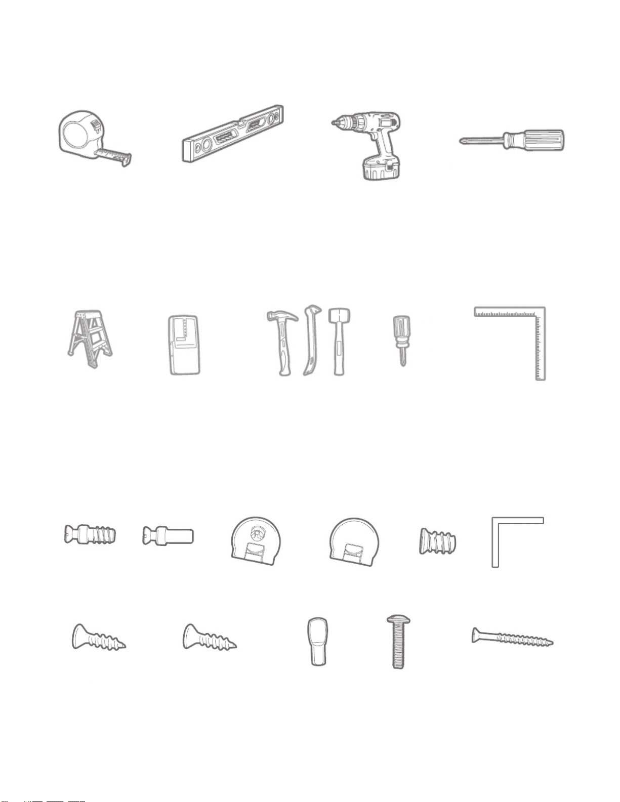
Required
&
Recommended T
ools................................................... 4
Hardware
Requirements.................................................................4
Typical Part Identification ..............................................................5
In
v
e
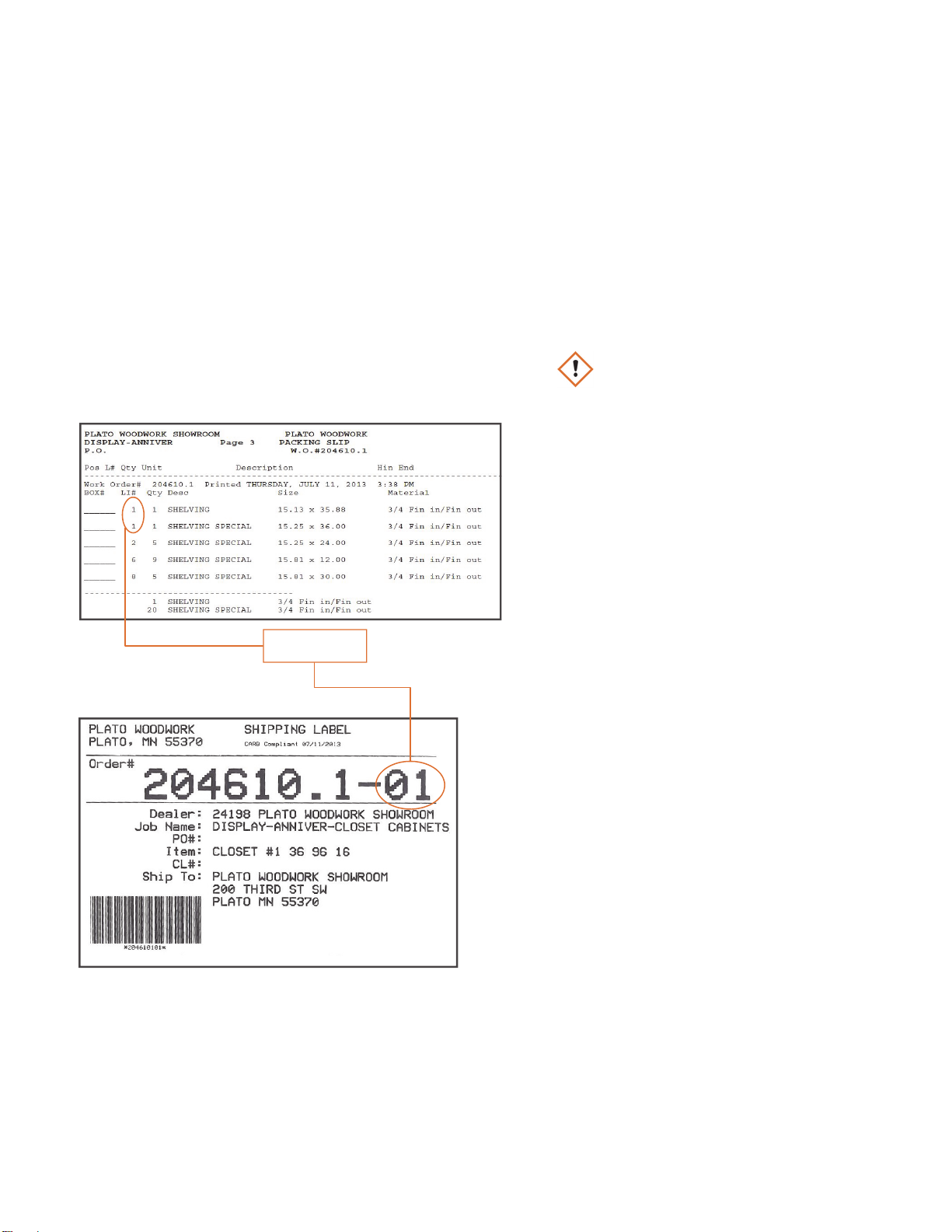
ntory Your
Shipment
................................................................ 6
Bef ore You Beg in ......................................................................7
BASIC INSTALLATION
INSTRUCTIONS
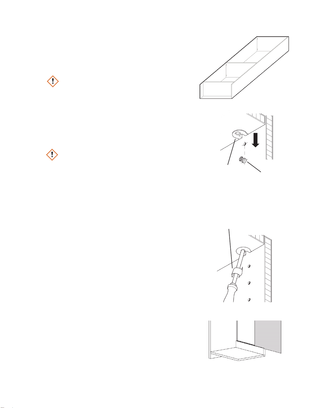
Typical Unit
.................................................................................. 8-11
Corner Spiral Clothes Pole Unit ........................................... 12
Corner Shelf Unit ........................................................................ 13
Blind Shelf Unit ............................................................................ 14
INSTALLING
COMPONENTS
Open Holes Between Components ....................................................15
Drawers .............................................................................................................16
Baskets................................................................................................... 17
Tilt-Out H
amper
...................................................................... 18
Slide-Out Hamper .................................................................. 19
Slanted Shoe
Shelv
es............................................................................ 20
S
helf-Mounted Ironing
Board ................................................... 21
Wardrobe Lift.............................................................................. 22
Doors .......................................................................................23
Adjustable
Shelves...................................................................... 24
Clothes Poles
.........................................................................................24
Belt Rack..................................................................................................24
Tie Rack....................................................................................................24
Scarf Rack ...............................................................................................24
Valet Pole................................................................................................24
Pants Rack Hanger ..............................................................................25
Hooks ........................................................................................................ 25
Pull-Out Mirror
.................................................................................. 25
PAGE #