PlayGoPools 2200 User manual

1
THE RECTANGLE POOL
MODEL # 2200
INSTALLATION MANUAL

2
Your pool is designed for years of pleasurable, safe family fun. But, when used
incorrectly, a swimming pool can be dangerous. To insure your pool is used safely
you must observe the following safety precautions:
1. Do not dive! - Do not jump! - No rough play! - No running or pushing!
2. Do not walk on the top ledge. It can be slippery and is not a walkway.
3. Be sure to install all safety labels provided with your pool according to the
instructions.
4. Keep a safety rope 1/4” by 50’ with a otation buoy with an outside diameter of
15”. Have accessible in a prominent area by your pool.
5. Post near all entrances to pool area a list of telephone numbers of the:
• Nearest available police • Nearest ambulance service
• Nearest available hospital • Nearest available re department
• Nearest available physician • Nearest available rescue unit
• 911 emergency number if available
6. Provide the fencing or enclosure which is independent of the house as a closure
around the entire pool area. e fencing must be made of durable material, a minimum
of 4’ in height from the ground level and with closures with self-latching locks, to make
your pool inaccessible to toddlers and uninvited guests. Make sure the gate is always
closed.
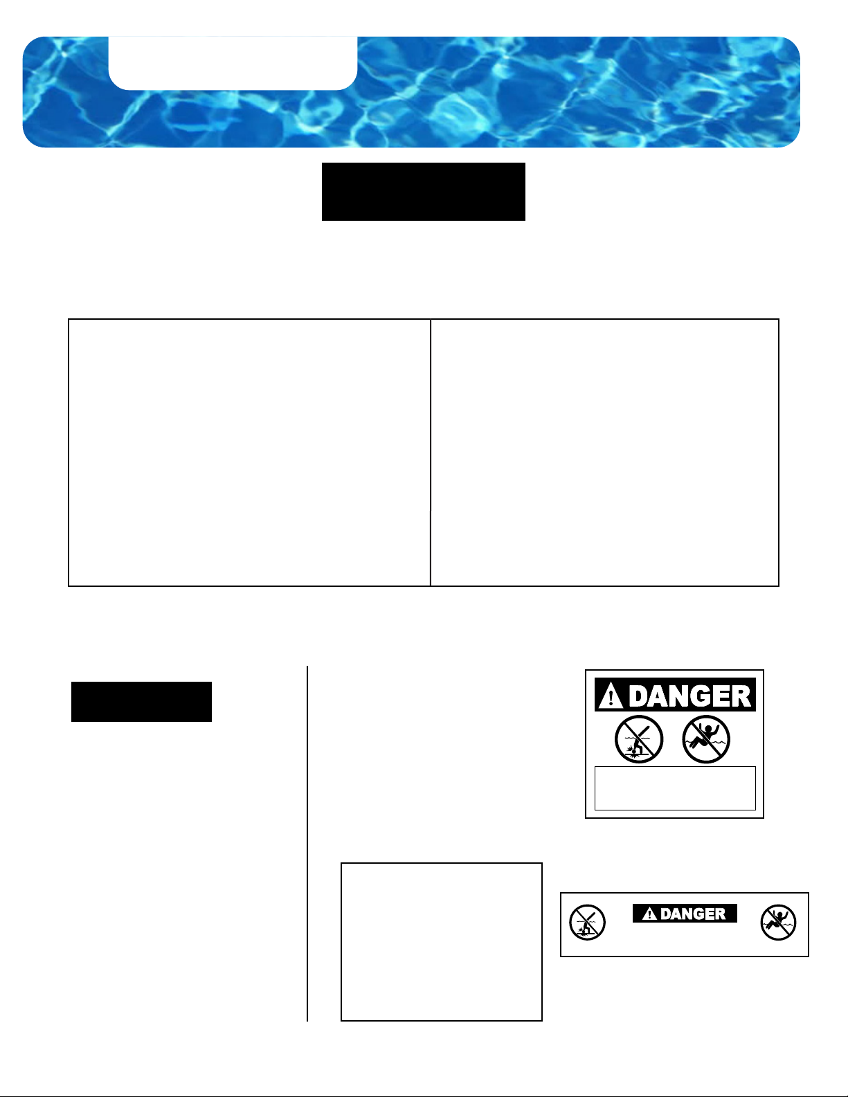
THIS POOL IS NOT DESIGNED FOR DIVING OR JUMPING.
DANGEROUS INJURY CAN RESULT - SHALLOW WATER!!!
Follow All Safety and Maintenance Instructions
WARNING
WARNING
WARNING
Be sure to follow local building code requirements for load capacity and fencing
if using an aermarket or homebuilt deck. You must make sure all fencing and
barriers are in working order so that pool is always protected.
7. Check with your local municipality for any special laws in your area. Never
drink alcoholic beverages or use any intoxicants which could hinder your judgment
and reexes.
8. Never use your pool alone. All children must be supervised continuously.
9. Do not use your pool if the bottom is not clearly visible: At night, sucient
lighting must be available. It is solely the pool owner’s responsibility to provide
an adequate lighting for the pool bottom, safety signs and walkways, which exceeds
minimum standards of the IES of North America.
10. Do not climb, stand or sit on any pool structure or the lter system. e
components such as the ltration system, pumps and heater must be positioned so
as to prevent their being used as a means of access to the pool by young children.
11. Be sure that all toys, chairs and tables or similar objects a young child could
climb on be at least 4’ from your pool.
12. Do not use your pool during electrical or rain storms.
13. See available Association of Pool & Spa Professional (APSP) publica-
tions for more tips on the pool safety.
THESE WARNINGS ARE NOT
TO BE REMOVED UNDER ANY
CIRCUMSTANCES! IF THEY
BECOME DISCOLORED OR
FALL OFF, PLEASE REQUEST
REPLACEMENTS, WHICH
WILL BE SENT AT NO CHARGE.
1920596 Rev. 0
NO DIVING - NO JUMPING
SHALLOW WATER
DIVING OR JUMPING MAY CAUSE DEATH
OR PERMANENT INJURY
IMPORTANT NOTICE! READ BEFORE INSTALLATION.
DO NOT AFFIX ANY OTHER
PRODUCTS MADE BY
OTHERS TO YOUR POOL
SUCH AS, BUT NOT LIMITED
TO, DECKS AND SLIDES!
ENCLOSED IN THE FRAME CARTON IS
AN ENVELOPE CONTAINING SAFE-
TY STICKERS, WHICH MUST BE IN-
STALLED AS PER THE FOLLOWING
INSTRUCTIONS. FAILURE TO PRO-
PERLY INSTALL WARNING LABELS
WILL VOID WARRANTY. FAILURE TO
MOUNT THESE SAFETY LABELS MAY
SUBJECT YOU TO SUBSTANTIAL
LIABILITY IN CASE OF INJURY.
SIGN MUST BE PLACED ON THE
WALL, NEXT TO THE POOL ENTRY.
SIGN TO BE PLACED ON
THE INSIDE LIP OF THE TOP
LEDGE.
NO DIVING - NO JUMPING
SHALLOW WATER

3
INTRODUCTION
1. Read through the entire instruction booklet before you begin. is will enable you to exactly nd
out what is involved in installing your swimming pool before you begin.
2. DO NOT ATTEMPT THE INSTALLATION IN WINDY OR GUSTY WEATHER. is will
not only make your installation more dicult, it may result in damage to your pool before it is completely
installed.
3. Although we have broken down the installation into many simple steps, you will probably nd that
steps 1 to 4 will be the most labor-intensive and time-consuming. Once you have completed those four steps
you should nd that the rest of the installation moves along much more quickly.
4. Please be sure to review all the safety material and local codes before beginning your installation.
ere is a safety envelope packed with your pool. is envelope contains the safety material and warning
stickers to be placed on your pool. If you are missing any of these items, please contact your dealer or the
factory to obtain it. e warranty is void if all the safety precautions are not followed.
5. In the event you need to make a warranty claim, it is important to know about the size and model
of your swimming pool in order to expedite the handling of your claim. Please ll in the information below
and keep for your records. All of this information can be found on the labels attached to the cartons your pool
is packed in.
6. Make sure you have all the necessary tools and materials before beginning your installation. Below
is a list of the tools and materials needed.
7. e actual pool design may not be exactly as pictured on our web site or brochures. e Pool
Factory, Inc. reserves the right to change and/or alter its pool designs at any time without advance notice.
Use only professional pool installers and professional tools for installing the pool by
all means.
Tools and Materials Required:
• Excavator truck or rototiller, surveyor’s tripod and transit level, carpenter level, tape
measure, hand rake, ground shovel, round-pointed shovel, wheel barrel, electrical drill, 1/8”
drill bit, impact gun with torque adjustment, 1/4” hex head socket, pool sand, patio blocks,
duct tape, garden hose with a water hook up.
• Use a professional impact gun with torque adjustment for screwing all the self-tapping screws
all over the pool by all means to avoid stripping aluminum and loosening the self-tapping screws.
CONGRATULATIONS ON BECOMING THE OWNER OF A NEW SWIMMING POOL.
THESE ARE INSTRUCTIONS FOR INSTALLING YOUR SWIMMING POOL.
THE FOLLOWING ARE SOME HELPFUL HINTS YOU SHOULD TAKE INTO
CONSIDERATION BEFORE INSTALLING YOUR POOL.

4
#ABOVE GROUND
POOL PARTS NAME
POOL SIZES
9 X 14
9 X 18
9 X 22
9 X 26
9 X 31
14 X 18
14 X 22
14 X 26
14 X 31
14 X 35
18 X 22
18 X 26
18 X 31
18 X 35
18 X 39
22 X 26
22 X 31
22 X 35
22 X 39
22 X 43
1-UN Wall
Panel 911 13 15 17 13 15 17 19 21 17 19 21 23 25 21 23 25 27 29
2-UN Bottom
Chanel 10 12 14 16 18 14 16 18 20 22 18 20 22 24 26 22 24 26 28 30
3-UN Top
Ledge 10 12 14 16 18 14 16 18 20 22 18 20 22 24 26 22 24 26 28 30
4-UN Corner
Post 44444444444444444444
5-UN Ledge
Cover 10 12 14 16 18 14 16 18 20 22 18 20 22 24 26 22 24 26 28 30
6-AG Buttress 6 8 10 12 14 10 12 14 16 18 14 16 18 20 22 18 20 22 24 26
7-AG Bottom
Strap 7 10 13 16 19 17 22 27 32 37 31 38 45 52 59 46 55 64 73 82
8-AG Pressure
Plate 6 8 10 12 14 10 12 14 16 18 14 16 18 20 22 18 20 22 24 26
9-AG Corner
Cap 444444444444444 44444
10-AG Buttress
Cap 6 8 12 14 16 10 12 14 16 18 14 16 18 20 22 18 20 22 24 26
11-AG Skimmer
Panel 111111111111111 11111
PART LIST - THE RECTANGLE

5
HARDWARE
Above Ground and Semi-In Ground Pool Exploded View:
#ABOVE GROUND
POOL PARTS NAME
POOL SIZES
9 X 14
9 X 18
9 X 22
9 X 26
9 X 31
14 X 18
14 X 22
14 X 26
14 X 31
14 X 35
18 X 22
18 X 26
18 X 31
18 X 35
18 X 39
22 X 26
22 X 31
22 X 35
22 X 39
22 X 43
*Self-
tapping
screws 1”
221
278
344
410
476
370
432
510
570
542
544
614
678
742
806
566
680
794
908
1,022
*Deection
Compensator 6 8 10 12 14 10 12 14 16 18 14 16 18 20 22 18 20 22 24 26

6
#INGROUND
POOL PARTS NAME
POOL SIZES
9 X 14
9 X 18
9 X 22
9 X 26
9 X 31
14 X 18
14 X 22
14 X 26
14 X 31
14 X 35
18 X 22
18 X 26
18 X 31
18 X 35
18 X 39
22 X 26
22 X 31
22 X 35
22 X 39
22 X 43
1-UN Wall
Panel 8 10 12 14 16 12 14 16 18 20 16 18 20 22 24 20 22 24 26 28
2-UN Bottom
Chanel 10 12 14 16 18 14 16 18 20 22 18 20 22 24 26 22 24 26 28 30
3-UN Top
Ledge 10 12 14 16 18 14 16 18 20 22 18 20 22 24 26 22 24 26 28 30
4-UN Corner
Post 44444444444444444444
5-UN Ledge
Cover 10 12 14 16 18 14 16 18 20 22 18 20 22 24 26 22 24 26 28 30
6-IG Buttress 6 8 10 12 14 10 12 14 16 18 14 16 18 20 22 18 20 22 24 26
7-IG Skimmer
Panel 111111111111111 11111
8-IG Return
Panel 111111111111111 11111
*
Self-
tapping
screws
1”
157
190
232
274
316
242
272
318
346
386
336
366
390
414
438
274
340
406
472
538
HARDWARE

7
In Ground Pool Exploded View:

8
ABOVE GROUND POOL
INSTALLATION
Ground Preparation
• Follow the 102” (2 panels) x 204” (4 panels) sketch provided above as your guide to install a rectangle
pool of any size. is sketch is universal for all rectangle pools’ sizes. Simply add or subtract 51” per
panel section and apply it to your pool’s size.
• First, square o and level the entire ground of your pool’s outer dimensions (Note: Outer dimensions
are always 3.5” wider than the inner dimensions). Next, dig out trenches every 51” apart between
every two wall panels for installing Buttresses under the ground, leveling ush with the ground. Please
make sure that the part of the trench located inside the pool is 20.25” long and the part of the trench
located outside the pool and accommodating the part of the Buttress having the Reinforcing Bracket
is 19.25” long according to the picture on the bottom on the right of the Page 9. ese trenches must
be four inches deep, four inches wide and thirty nine and a half inches long to accommodate all
buttresses. Also, at the ends of each Horizontal Buttress located on the dry/outside side of the pool, dig
6” (deep below the ground level) x 10” x 8.5” additional pits to accommodate 2” (thick) x 8”x 8” patio
blocks, making sure that the centers of the patio blocks will be centered and placed under the end of
each Horizontal Buttress. Next, please dig four 1.5” (deep) x 8.5” x 8.5” square pits to accommodate
four 2” (thick) x 8”x 8” patio blocks at all the four corners of the pool as shown on the illustrations on
the Page 9.
• Designate the place of the Skimmer, Filter and Return (or Two Returns), making sure that they
should be placed one panel o the corner (please see Page 23 for your reference as an example). If
your pool is quite big, please diagonally station the second return on the opposite side of the pool to
provide the pool with eective and ecient water circulation.
For 52” Above Ground Installation:
Choose Skimmer, Return(s) and Filter Location
IMPORTANT: Before starting the Installation Process, PLEASE read the entire Instruction
carefully and comprehensively step-by-step to follow all the information mentioned. Otherwise,
if you do not follow the Instruction out completely, the Pool Warranty attached to the Instruction
will become void. Please take into account that the textured surface of the pool panels should be
located on the outside/dry side of the pool and smooth surface – on the inside/wet side of the pool.

9
Patio Blocks Placement
• Square o and level four 8” (width) x 8” (length) x 2” (thickness) corner patio blocks 0.5” above the
ground level according to your pool size as shown on the illustration below. ese patio blocks will be
4.5” higher than the buttress patio blocks.
• Next, square o and level buttress patio blocks (centered every y one inch apart from each other
[six inches in ground]) in ground, placing the centers of the buttress patio blocks sixteen inches away
from your pool’s outer (dry side) wall size per sketch. Use a surveyor’s transit or carpenter level to
make sure that all the tops of the patio blocks are exactly square and level with the top of the ground
and with each other.
IMPORTANT: When stationing all the corner patio blocks, please make sure that all of these
patio blocks stick out 0.5” above ground level by all means. Also, when disposing all the buttress
patio blocks under the dry/outside ends of the Horizontal Buttresses, please place the 2”x2”x0.75”
Deection Compensators (provided with the hardware) under the dry/outside ends of the
Horizontal Buttresses, making sure that all of these dry/outside ends of the Horizontal Buttresses
stick out 0.75” above ground level by all means (the wet/inside ends of the Horizontal Buttresses
should not stick out above ground level at all) according to the pictures on Page 10.
ABOVE GROUND POOL
INSTALLATION

10
• Please see the Corner Section illustration below, showing the 0.5” elevation of the Patio Block above
the ground level.
• Please see the Buttress Assembly illustration below, showing the 0.75” elevation of the dry/outside
end of the Horizontal Buttress (above the ground level) raised by Deection Compensator provided
in the box with the hardware.

11
Step 1
• Screw twelve 1” self-tapping screws through two Top Ledges and two Bottom Channels into one
Corner Post and two Wall Panels to build a Corner Section as pictured below.
Note: Screws for the Top Ledges should be located only on the outer/dry side of the pool. Before
screwing for easier screwing, please pre-drill all the necessary openings by using a 1/8” drill bit through
the factory pre-drilled ¼” openings.
• Use the pre-drilled holes located on the Top Ledges and Bottom Channels as your guide.
IMPORTANT: When placing two Top Ledges over the Wall Panels at the corner, please make
sure that you put them a little bit farther from the Corner by all means, making a very small gap
between the Corner and Top Ledges and providing the place for locating the Corner Cap later
(please see two pictures below).
Pre-assembling Corner Sections:

12
• Next, repeat this process three more times to build four total Corner Sections.

13
Step 2
Assembling Middle Sections:
IMPORTANT: When assembling, please make sure that all the Reinforcing Brackets of the But-
tresses are located on the dry/outer side of the pool.
• Screw six 1” self-tapping screws into the top openings (leaving the lower openings empty) through
two Top Ledges and two Bottom Channels into one Buttress Post and two Wall Panels to attach a
middle section as illustrated below.
Note: Screws for the Top Ledges should be located only on the outer/dry side of the pool. Before
screwing for easier screwing, please pre-drill all the necessary openings by using a 1/8” drill bit through
the factory pre-drilled ¼” openings.
• Use the holes located on the Top Ledge and Bottom Channel as your guide.

14
• Further, repeat this process for all the Middle Sections.
Note: Leave one Middle Section out to allow an entry point to cart sand into the pool area.

15
Step 3
Loading Sand:
• Wheel barrel the appropriate amount of clean pool sand (based on your size pool) inside the pool
area and place it on the oor in one corner.
Note: Do not block or impede the pathway of the Bottom Straps, which will run from one Buttress
Assembly to the opposite Buttress Assembly.
IMPORTANT: If there is some rm uneven soil or clay on the pool spot, please evently spread
some pool sand all over the pool place to provide the even surface for placing pressure plates at
Step 6.

16
• Close the pool o by attaching the last Wall Panel as done in Step # 2.
Assembling Last Middle Section:
Step 4

17
• Recheck pool, making sure that all of the Wall Panels are exactly squared o and the same height
level with each other.
• Next, by placing one Bottom Strap onto one Horizontal Buttress, inside the pool, (starting at the
pre-scribed line located 5” from the end of a Horizontal Buttress) fasten them together by, rst,
pre-drilling four 1/8” openings in the Horizontal Buttress through the diamond-shaped positioned
holes located in the upper Bottom Strap as your guide and, then, tightly screwing four 1” screws
through these diamond-shaped positioned holes located in the upper Bottom Strap as your guide into
the Horizontal Buttress as illustrated on the next page.
Step 5
Installing Bottom Straps:
e pre-scribed line located 5” from the end of a Horizontal Buttress.
• Further, repeat this process with all the Bottom Straps and Horizontal Buttresses.
• Next, connect one Bottom Strap to another (from one Buttress Post to the opposite Buttress Post,
exactly across from each other, facing the north/south and the east/west directions) across the entire
bottom of the pool by, rst, pre-drilling four 1/8” openings in the lower Bottom Strap through the four
diamond-shaped positioned holes located at the end of the upper Bottom Strap as your guide and,
then, tightly screwing four 1” screws through these diamond-shaped positioned holes located at the
end of the upper Bottom Strap as your guide into the four pre-drilled 1/8” openings located at the end
of the lower Bottom Strap at each connecting place. When connecting Bottom Straps, please overlap
the straps by exactly 4”.

18
• Next, repeat the above-mentioned process for connecting all of the Bottom Straps to each other.
• e excess strap material of the center Bottom Straps must be located underneath each continuous
run of Bottom Straps.
• Next, recheck to make sure that all of the Wall Panels are exactly squared o and the same height
level with each other.
• Finally, connect the last center Bottom Straps by drilling out the upper Bottom Straps in all of the
continuous runs of all of the Bottom Straps (use the exact same diamond-shaped pattern copied from
any Bottom Strap as a guide for drilling these nal straps out) and then screw four 1” screws through
these openings into the lower Bottom Straps (place a piece of wood under the Bottom Straps when
drilling and screwing down for convenience).
Note: Do not connect the north/south running Bottom Straps to the east/west running Bottom Straps.

19
Step 6
Mounting Pressure Plates:
IMPORTANT: It is critical that all of the Pressure Plates are always placed and screwed down,
starting from the very end of the Horizontal Buttresses (on the wet side).
• Center each Pressure Plate over one Horizontal Buttress, placing it at the end of each 39” Horizontal
Buttress. Make sure that the edges of the Pressure Plates are located just at the end of each Horizontal
Buttress according to the illustration below.
• Further, evenly spread out and screw down each Pressure Plate to each Horizontal Buttress by using
three 1” self-tapping screws provided for each connection as pictured below.
Note: Before screwing, please pre-drill three 1/8” openings in each Pressure Plate and each Horizontal
Buttress at each connecting place for easier screwing.
• Next, overlap and screw down each Pressure Plate to the next Pressure Plate along the side of it as
shown in the illustration by using three 1” self-tapping screws provided for each connection.
Note: Before screwing, please pre-drill three 1/8” openings in both Pressure Plates at each connecting
place for easier screwing.

20
Step 7
Final Assembling All Middle Sections:
• Recheck all levels and squareness of the pool, making sure that all of the Wall Panels are exactly
squared o and the same height level with each other.
• Screw the other six 1” self-tapping screws into the lower openings through two Top Ledges and two
Bottom Channels into one Buttress Post and two Wall Panels to nally and rmly attach a middle
section as pictured below.
Note: Screws for the Top Ledges should be located only on the outer/dry side of the pool. Before
screwing for easier screwing, please pre-drill all the necessary openings by using a 1/8” drill bit through
the factory pre-drilled ¼” openings.
• Use the holes located on the Top Ledge and Bottom Channel as your guide.
• Further, repeat this process for all the Middle Sections.
• en, nally thoroughly recheck all levels and squareness of the pool again, making sure that all of
the Wall Panels are exactly squared o and the same height level with each other.
• NEXT, NOW, AT THIS POINT, GO BACK AND VISUALLY AND BY TOUCH CHECK THE
TIGHTNESS OF ALL THE SCREWS OF THE ENTIRE POOL.
Table of contents
Popular Swimming Pool manuals by other brands

The Pool Factory
The Pool Factory Saltwater Aurora installation manual

Bestway
Bestway Family Pool Sippin Summer manual

Bestway
Bestway InflateYourFun Fast Set owner's manual

Outside Living Industries
Outside Living Industries Ubbink OCEA Note of assembly

CPA
CPA Acquamarina Assembly and maintenance guide

welldana
welldana Elba installation manual