Air Ventilation
To have a soothing sauna, there should be a proper mixing of hot and cold air inside the
sauna room. Another reason for ventilation is to draw air around the heater and move the
heat to the farthest part of the sauna.The positioning of the inlet and outlet vents may
vary depending on the design of the sauna room or preference of the owner.
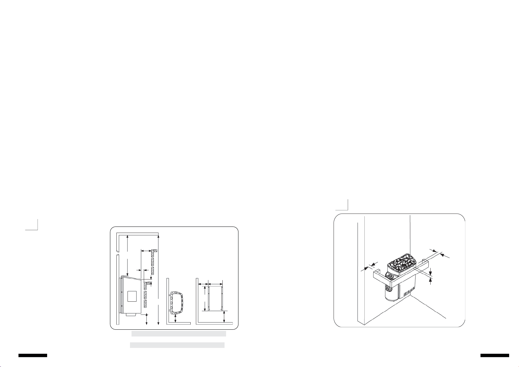
The inlet vent may be installed on the wall directly below the heater (Fig. 10A).When
using the mechanical ventilation, inlet vent is placed at least 60 cm above the heater (Fig
10B) or on the ceiling above the heater (Fig.10C).Through these positions, the heavy cold
air that is blown into the sauna is mixed with the light hot air from the heater, bringing
fresh air for the bathers.The inlet vent must have a diameter of 5-10cm (recommended).
The outlet vent should be placed diagonally opposite to the inlet. It is recommended that
the outlet vent is placed under the platform in a sauna as far as possible from the fresh air
vent.It may be installed near the floor, or led outside through a pipe from the floor going
to a vent to the sauna ceiling, or under the door (to the washroom).In this case, the sill slot
must be at least 5 cm and it is recommended that there is mechanical ventilation in the
washroom.The size of the exhaust should be twice that of the inlet.
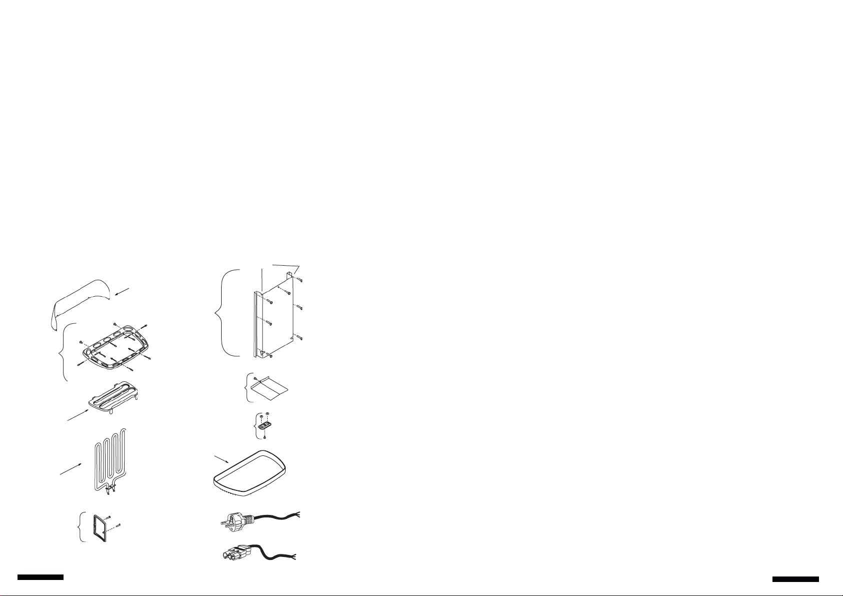
Insulation
The sauna must have proper insulation on the walls, ceiling and door.One square meter
(m²) of uninsulated surface increases the cubic volume by approximately 1,2m³ when
determining the power requirement of the heater. Refer to Fig.9.
Ensure that moisture proofing is appropriate in sauna room.The purpose of this is to
prevent spreading of moisture to the other rooms or wall structure.Moisture proofing must
be placed between heating insulation and panel.Nordic spruce wood is recommended for
the walls and ceiling inside the sauna.
Thermal and moisture proofing need to be installed according to the following order from
outside to inside.
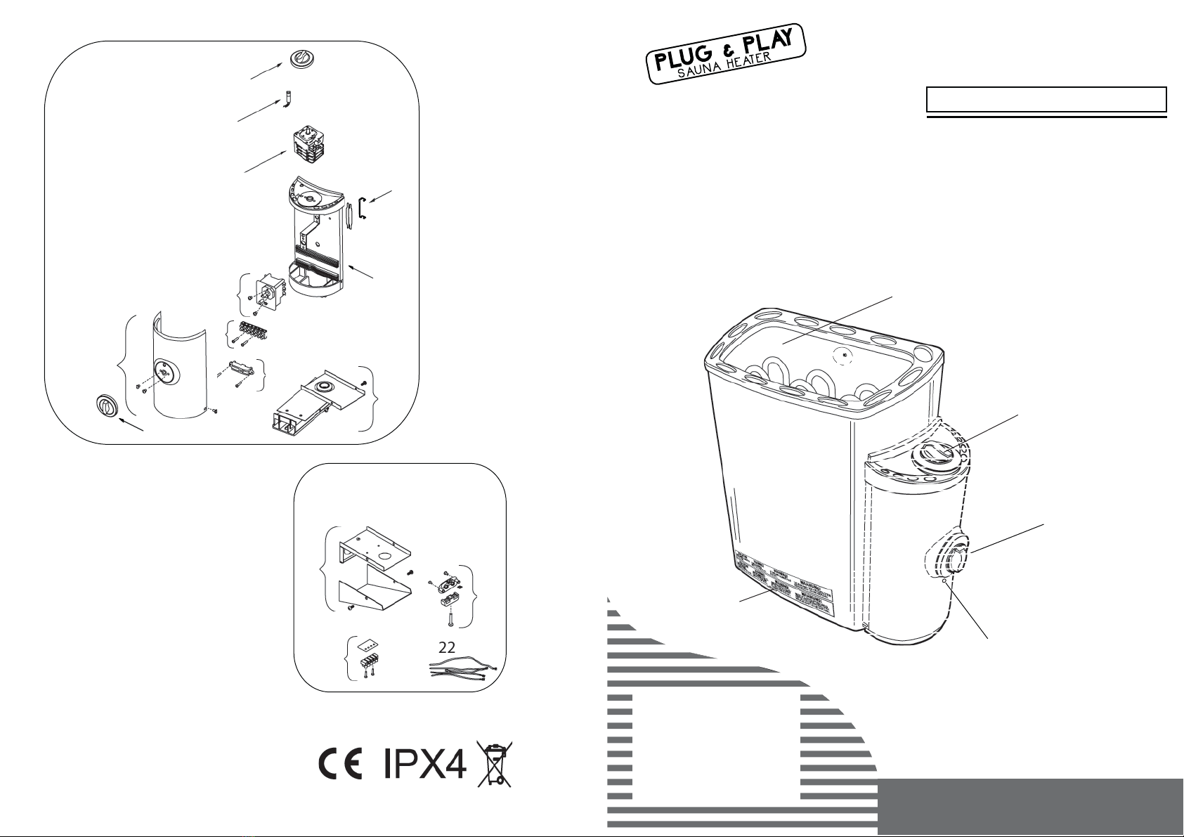
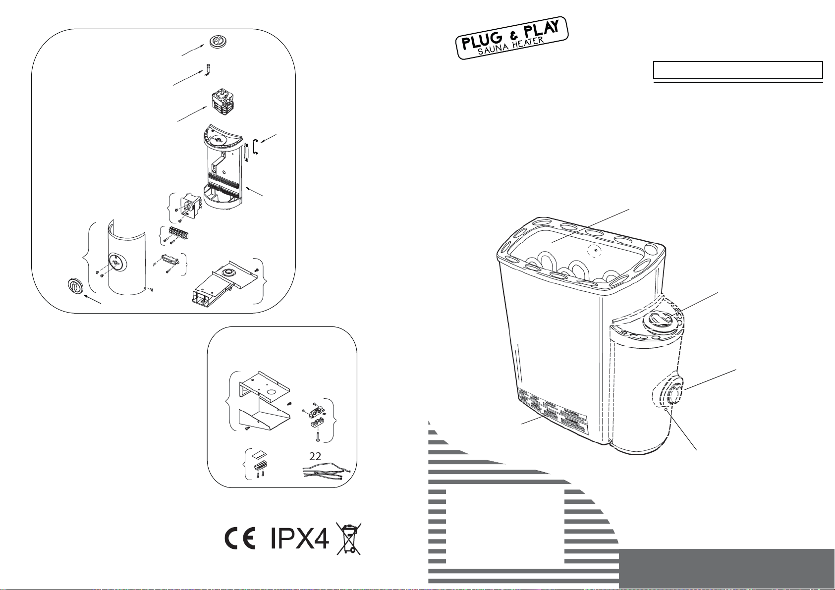
TIMER
Control Settings
Adjust the temperature of the sauna by simply turning the operating knob.Thermostat
support automatically the choosen temperature.
In case the heater overheats, the safety sensor will automatically stop the heater even if the
timer is on. Find out for what reason the heater overheated.The reason for this could be too
tightly placed sauna stones,heater´s location or inappropriate ventilation. If this occurs, find
out the cause and fix the problem before resetting the safety sensor.The reset button is
located below the temperature knob.
To start the heater at once,turn the knob to anywhere between 1-4 on the operating time
scale.The heater will start and remain on for the time selected.
THERMOSTAT
The recommended minimum thickness of the thermal insulation in the walls is 50 mm and in the
ceiling 100 mm.
It is possible to use carton- or aluminum foil laminate as a vapor barrier, which is affixed over the
insulation aluminum foil inwards.
Leave at least 20 mm air slot between vapor barrier and inside panel
To prevent gathering of the moisture behind the panel,leave the slot between wall panel and
ceiling.
1.
2.
3.
4.
AB C
Abb. 10
Fig. 10
9
DEUTSCH / ENGLISH
Zeitschalter
Timer
8
Lüftung
Zum Saunavergnügen ist eine richtige Mischung der heißen und der kalten Luft innerhalb der
Sauna erforderlich. Ein weiterer Grund für die Lüftung ist das Ansaugen der Luft rund um das
Heizgerät und die gleichmäßige Verteilung der Wärme in der gesamten Sauna. Die Anordnung der
Luftein- und Austrittsöffnungen kann in Abhängigkeit vom Design des Saunaraums oder nach
anderen persönlichen Wünschen gestaltet werden.Es empfiehlt sich, Nordisches Fichtenholz für
die Wände und die Decke im Inneren der Sauna zu verwenden.
Die Lufteintrittsöffnung kann an der Wand direkt unter dem Heizgerät (Abb. 10A) installiert
werden.Wird die künstliche Lüftung eingesetzt, kann die Eintrittsöffnung wenigstens 60 cm über
dem Heizgerät (Abb.10B) oder auf der Decke über dem Heizgerät (Abb.10C) angebracht sein. Auf
Grund dieser Anordnung wird die schwere kalte Luft, die in die Sauna geblasen wird,mit der
leichten heißen Luft des Heizgerätes gemischt und bringt den Badenden frische Luft zum Atmen.
Die empfohlene Größe der Lufteintrittsöffnung ist 5-10 cm.
Die Luftaustrittsöffnung sollte diagonal gegenüber der Eintrittsöffnung liegen.Es empfiehlt sich,
die Austrittsöffnung in einer Sauna unter der Plattform,möglichst weit von der Frischluftöffnung
entfernt,zu installieren.Sie sollte nah am Boden installiert sein oder durch ein Rohr aus dem Boden
zu einer Öffnung in der Saunadecke oder unter der Tür (in den Waschraum) geführt werden. In
diesem Falle mußdie Schwellenrille mindestens 5 cm betragen und es empfiehlt sich, den
Waschraum mit künstlicher Lüftung auszustatten.Die Größe der Luftabfuhröffnung sollte das
Zweifache der Eintrittsöffnung betragen.
Isolierung
Die Wände, die Decke und die Tür des Saunaraums müssen mit entsprechender Isolierung
versehen sein.Wenn man den Energiebedarf des Heizgeräts bestimmt, erhöht ein Quadratmeter
(m²) einer nicht isolierten Oberfläche den Kubikinhalt um ungefähr 1,2 m³ (Abb.9).
Der Saunaraum muß ausreichend isoliert sein, um ein Eindringen von Feuchtigkeit in die Wände
oder in Nebenräume zu vermeiden.Zwischen Heizungsisolierung und Bauplatte muß eine
Feuchtigkeitssperre angebracht werden.
Die Wärmedämmung und die Feuchtigkeitssperre sind in der nachstehenden Reihenfolge von
außen nach innen zu installieren.
ZEITSCHALTER
Einstellungen
Die Temperatur der Sauna stellen Sie einfach durch das Drehen des Regelknopfs
ein. Durch die Temperatursteuerung wird die laufende Temperaturebene
programmierbar erfaßt und die durch die Sensoren gewählte Wärme
automatisch geliefert.
Wenn es zur Überhitzung des Heizgeräts kommt, wird der Sicherheitssensor das
Heizgerät automatisch stoppen,selbst wenn der Zeitschalter eingeschaltet ist.
Stellen Sie die Ursache der Überhitzung fest.Sie kann durch zu dicht aneinander
gelegte Saunasteine, die unrichtige Anbringung des Heizgeräts oder
unzureichende Lüftung verursacht sein.Beseitigen Sie die Ursache des
Problems, bevor Sie den Thermostat neu einstellen. Die Reset-Taste befindet
sich unter dem Temperaturreglerknopf.
Zur sofortigen Einschaltung des Heizgeräts drehen Sie einfach den Knopf auf
einen beliebigen Wert zwischen 1 und 4 auf der Betriebszeitskala. Das Heizgerät
schaltet sich ein und bleibt für die gewählte Zeit in Betrieb.
TERMOSTAT
Die empfohlene Mindeststärke der Wärmedämmung an den Wänden beträgt 50 mm
und auf der Decke 100 mm.
Es kann entweder Pappen- oder Aluminiumfolie-Laminat als Dampfsperre verwendet werden,
das über der Aluminium-Isolierfolie innen befestigt wird.
Zwischen der Dampfsperre und der Innenbauplatte mußeine Luftspalte von mindestens
20 mm verbleiben.
Um Feuchtigkeitsbildung hinter der Bauplatte zu vermeiden, ist eine Nut zwischen der
Wandplatte und der Decke zu behalten.
1.
2.
3.
4.
Thermostat
DEUTSCH / ENGLISH