NU S125-SHR3-21 User manual

AFTER SALES SUPPORT
2
Contents
03 Warranty Page
04 Welcome Section
05 Parts List
06 General Information, Safety Instructions and Compliance
07 Features
08 Before installing
08 Installation
09 Electrical Wiring
10 Wiring Diagram, Operation and Cleaning
11 Technical Data and Frequently Asked Questions
11 Disposal
Warranty Details
The product is guaranteed to be free from defects in workmanship and parts for a
period of 24 months from date of purchase. Defects that occur within this warranty
period, under normal use and care, will be repaired, replaced or refunded at our
discretion, solely at our option with no charge for parts and labour. The benets
conferred by this warranty are in addition to all rights and remedies in respect of
the product that the consumer has under the Trade Practices Act and similar state
and territory laws.
Parts List
1. Bathroom heater lamp
2. 8W LED Downlight
3. 275W heat lamp (4)
4. Ducting kit
5. Exterior vent
6. 4 way switch
1300 014 916

AFTER SALES SUPPORT
3
General Information and Safety Instructions
Please read all instructions before commencing installation even if you feel you are quite familiar with
this type of product.
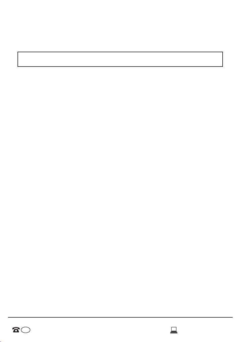
THE NU EXHAUST FAN, HEATER & LIGHT MUST BE INSTALLED BY A QUALIFIED ELECTRICIAN, AND
AN ELECTRICAL SAFETY CERTIFICATE MUST BE ISSUED ON COMPLETION OF THE INSTALLATION.
• This product must be used only as described in this manual. Any other use not recommended by
the manufacturer may cause re, electric shock, or injury to persons. If you have questions, contact
the manufacture or local agent.
• All wiring must be carried out by a licensed electrician in accordance with all applicable national/
local codes and standards. Also check with the local council regulations regarding installation of
exhaust fans.
• Ensure the power is disconnected prior to the installation.
• When cutting into the ceiling, care must be taken to ensure you do not damage electrical wiring
and other hidden utilities.
• The heater must be properly earthed/grounded.
• The infrared globes are extremely hot when in use. Do not touch the globes with any part of your
body when in use. Allow all globes to cool suciently before touching or replacement.
• For the purpose of avoiding any fumes leaking into your bathroom, the duct for the heater must
not be laid together with ducts for air-fueled water heaters or other open-re appliances.
• Power cable used for wiring must be rated for a minimum 10A load.
• Do not install unit near curtains or other combustible materials.
• Regularly maintain the unit to clear dust which may restrict airow.
• Replace all globes with the same or lesser wattage.
• Product is for indoor domestic use only and not for commercial, industrial or trade use.
• The appliance is not to be used by persons (including children) with physical, sensory or mental
capabilities, or lack of experience and knowledge, unless they are supervised or given instructions.
• The appliance is not to be covered in insulation.
• Ensure local regulations concerning discharging of air are adhered to.
• Do not cut or notch joists, beams or rafters to install this appliance.
• Children should be supervised to ensure that they do not play with the appliance
Compliance
AS/NZS 60335-2-30:2009+A1-2 Household and similar electrical appliances -
Safety Part 2.30: Particular requirements for room heaters
AS/NZS 60335-1:2011+A1-3 Household and similar electrical appliances -
Safety Part 1: General requirements
AS/NZS CISPR 15:2011 Limits and methods of measurement of radio disturbance
characteristics of electrical lighting and similar equipment.
AS/NZS IEC 62560:2014 Self-ballasted LED-lamps for general lighting services by
voltage > 50 V - Safety specications
1300 014 916

AFTER SALES SUPPORT
4
Features
Light
• 8W LED Downlight included.
Heat
• 4 x 275W E27 Heat lamp
globes provide instant heat.
Centrifugal Fan
• Exhaust fan keeps your bathroom
steam and odour free by extracting
air at a rate of 300m3per hour.
• Vent and ducting kit helps reduce heat
loss and prevents dust and dirt falling
from your ceiling cavity.
Switch
• 4 individual controls for your light, heater and fan. Dual ability to have 2 or 4 heat lamps
on.
• This unit is tted with a thermostat switch which will operate to automatically switch the
exhaust fan on, in the event that the heat globes are accidentally left on, and the internal
temperature of the unit exceeds 80°C.
Specications
Cut out hole: 310 x 300mm
To suit medium sized bathrooms with ceiling height up to 2.85m
Dimensions: 369.9mm (length) x 369.9mm (width) x 271.1 (height)
Mass: 4.3Kg
1300 014 916

AFTER SALES SUPPORT
5
Before Installing
PLEASE NOTE: Must be installed by a licensed electrician.
A few minutes planning can make a big dierence to the installation time and also to your satisfaction
with the function of your bathroom heat lamp.
• Before commencing any cutting, check in the ceiling space that there are no obstructions such
as ceiling joists (at least 50mm clearance) and that there is sucient height clearance (at least
220mm) from the unit. Check if the electrical wiring can be routed from the wall switches to the
mounting location.
• This bathroom heat lamp must be installed at least 2.1m above the oor. Ceiling height cannot
exceed 2.85m.
• This heater is to be installed so that switches and other controls cannot be touched by a person in
the bathtub or shower.
• Ceiling insulation should be kept well clear away from the unit and all ducting equipment.
• The unit should not be installed directly above a shower or bathtub.
• The unit must not be installed where it will be subject to direct splashing.
• Your bathroom heat lamp is designed for installation in at ceilings only. Don’t mount on a sloping
ceiling or a vertical wall.
• The infrared lamps are not designed to heat the entire room area; they provide instant heat to
persons standing directly below them. Install your bathroom heat lamp above the area where
‘drying o’ usually occurs.
• Your bathroom heat lamp has not been designed for extended periods of operation, as this could
cause overheating and premature failure.
• For the exhaust fan to work eciently, air ow of a volume equivalent to what is being extracted
must be able to enter the room.
• In general, air would be drawn under the door, or through a slightly open window. If the room is
airtight, the fan will function poorly.
• The distance between the sides of the heater and the sides of any adjacent ceiling recessed heater
shall not be less than 200mm
Installation
• Please read these instructions carefully before installing and using the product. Keep the instruc-
tions handy for future reference.
• Electrical wiring must only be done by a licensed electrician and a “Certicate of Compliance” must
be issued upon completion of the installation.
LOCATION
• The unit must be located and installed in accordance with AS/NZS 3000 and local building codes
and regulations concerning the discharge of air have to be fullled.
• The unit can be installed in any room that requires direct radiant heating and circulated air
ow such as bathrooms, ensuites, laundries etc. The unit can be installed in at ceilings with a
minimum height of 2.1 metres. At least 250mm height clearance in the ceiling cavity is required
to ensure sucient ventilation for moisture to disperse. The unit must also be installed at least
400mm away from the walls.
• Ensure adequate inlets exist through windows, vents or under the door for airow.
1300 014 916

AFTER SALES SUPPORT
6
POWER
• AC220-240V, 50/60Hz electrical supply is required. The unit can be connected to a lighting or power
circuit if loading permits. All electrical work must be carried out in accordance with AS/NZS 3000 or
latest edition thereof.
MOUNTING
1. The unit may be mounted either between joists using the inbuilt clip fasteners or against a joist
using a screw through the ange plate. Use this card in its open state as a template. Place in the
required location and mark out the hole cutting size. Hole size is 310 x 300mm.
2. Before commencing cutting ensure that the area behind the intended location is clear of all cables,
pipes and joists. Once clear, cut out the section along the previously marked lines.
3. Remove 2 heat lamps from the bathroom heater, then remove the plug of the LED downlight inside
the housing. Unfasten the fascia. Connect the ducting if required to the outer grill of the unit. Insert
the unit into the square hole being sure to pull the side springs inward so that the body can pass
through the hole without damaging the plaster. Ensure that the unit is held securely in place by the
clips. If required, additional screws can be used to aid holding the unit in the ceiling. Screw holes are
provided in the ange for this purpose.
4. Connect the LED downlight plugs rst. Hold the fascia against the body of the heater and the ceiling
and attach the securing spring clips to hold the fascia in place.
5. Now screw in the two large heat lamps into the lamp holder through the holes provided in the
fascia. The globes should be screwed up rmly to ensure a good electrical contact but don’t over
tighten.
ELECTRICAL WIRING
This product must be installed by a qualied electrician. This bathroom heater unit must be wired
through either a plug and socket or an all-pole disconnecting switch (SW 1) in accordance with Australian
& New Zealand Wiring Rules AS/NZS 3000.
NB: This unit is tted with a thermostat switch which will automatically switch the exhaust fan on, in the
event that the heat globes are left on, and the internal temperature of the unit exceeds 80ºC.
1. Ensure that the power is turned o before carrying out any work on electrical installations.
2. Clip the switch into the backing plate in the desired order and install the plate on the wall.
3. Connect the wiring to the three switches as shown in the electrical diagram (page 7).
4. Remove the terminal cover on the heater unit and wire according to the label adjacent to the
terminal block. Make sure all cables are securely connected and ret the terminal cover.
5. Clean the fascia and globes with a soft moist cloth. Turn on power and check the switch operation.
NB: Internal wiring of product must not be modied in any way.
1300 014 916

AFTER SALES SUPPORT
7
Wiring Diagram
Operation
Your bathroom heat lamp uses infrared heating globes as a source of heat. It also combines
the functions of exhaust and light.
Heating
• Turn on/o “heat”switch/es to activate the heat lamps.
• Your bathroom heat lamp is supplied with two banks of infrared lamps. You can turn on
one or both of them for best heating eect.
Exhaust fan
• Turn on/o “fan”switch to activate the exhaust fan.
• Your bathroom heat lamp will exhaust odours and steam in a quick and ecient manner.
Lighting
• Turn on/o “light”switch to activate the centre light globe.
1300 014 916

AFTER SALES SUPPORT
8
Lamp Replacement
Switch o power to unit and allow unit to cool. Remove Lamp and replace with similar mod-
el ensuring the power ratings are not exceeded.
Cleaning
• Switch o power at the wall before commencing cleaning, and allow unit to cool to
room temperature.
• Remove all globes from your bathroom heat lamp unit.
• Unfasten the facia-retaining springs inside the housing and remove the fascia.
• Regularly wipe globes and fascia using a soft cloth soaked with neutral detergent.
Ensure the globes have cooled to room temperature before handling.
• The exhaust fan requires regular cleaning to ensure optimum performance. With the
wall power switch o, regularly wipe the fan clear of all dust and dirt.
• Clean the exhaust ducting kit, ensuring there are no obstructions at the exit.
• Reassemble in reverse order.
Technical data
Model
Number
Rated
Voltage
Heat
Lamp
Rated
Power
Centre
Lamp
Rated
Power
Airow Lamp
Type
IP Rating Fan
Power
S125-SHR3-21 240VAC,
50Hz
4 x 275W 1 x 8W
570lm
300 m3/h E27 IPX4 2W
Frequently Asked Questions
Q: Will the bathroom heater lamp heat the entire bathroom?
A: No, the bathroom heater lamp is using infrared heat to warm
the body. It is not designed to be a room heater.
Q: What is the maximum light bulb wattage that can be used
with the bathroom heat lamp?
A: 8W max downlight and 275W heater lamp bulbs.
Disposal
Please dispose of this product thoughtfully once is it passed its useful life. When your light
tting comes to the end of its life or you choose to update or upgrade it, please do not
dispose of it with your normal household waste. Please recycle where facilities exist. When
disposing of this tting, check with your local authority for suitable options.
1300 014 916
Model No:
S125-SHR3-21
Jiaxing Mingliu Electric,
Henggang Industrial,
Baibu Town, Haiyan. Tiaxing
Made in China
C
M
Y
CM
MY
CY
CMY
K
manual-Model-S125SHR321-45x55.pdf 1 27/5/19 1:46 pm
Table of contents
Popular Heater manuals by other brands

HearthStone
HearthStone 8890 Owenrs manual

SImx
SImx MANROSE FAN5875 installation instructions

UFO
UFO LC20EN Flora User manual & certificate of warranty

Detroit Radiant Products
Detroit Radiant Products EDX Series Installation, operation, maintenance and parts manual

Klarstein
Klarstein HARRISON 10045584 manual

Smiths
Smiths HL 1000 user manual

Master
Master MH-60VBOA-GFA User's manual & operating instructions

Trane
Trane Arctic PolyTherm TP Series Installation, operation and maintenance

Etherma
Etherma SPH Installation and usage instructions

Brant Radiant Heaters
Brant Radiant Heaters AVS-40N instructions

Desa
Desa SB70DT owner's manual

Saturn
Saturn ST-HT 7645K quick start guide