Plug-In Solar Adjustable Ground Mount Kit User manual

Plug-In Solar Installation Instructions
Ground/Flat Roof Mount Kit with Adjustable Mounts
Plug-In Solar – Power Your Future
www.pluginsolar.co.uk
These installation instructions contain important information on safety matters and the installation
of the Plug-In Solar kit. Please read this guide carefully to ensure safe installation and operation.
*Installations are undertaken at the customer’s own risk. This Installation manual is to be used as a guide only, and your discretion
must be used when installing the Plug-In Solar kit.You MUST follow ALL local regulations and consult a professional in the
appropriate field if you are in any doubt with any aspect of the installation. Plug-In Solar Ltd takes no responsibility for incorrect
installation of our kits.

Plug-In Solar Ltd
289 London Road | Burgess Hill | West Sussex | RH15 9QU
www.pluginsolar.co.uk | info@pluginsolar.co.uk | 01444 672005 Page 2
TABLE OF CONTENTS
Tool Requirements
3
Component Guide
4
Safety Instructions
5
Warnings
6
Step by Step Plug-In Solar Installation Guide
Solar Panel Installation
Adjustable Metal Mount Installation
7
12
Micro-Inverter Installation
15
Wiring The Solar To The Existing Mains Circuit
19
Isolation/Isolator Requirements
21
Placing Warning Labels
22
Inspecting, Testing and Commissioning
Inspecting and Testing your Plug-In Solar Installation
23
Commissioning your Plug-In Solar Installation
24
Completing your Warranty Card
Completing your Solar Installation
26
27
Appendix
Appendix 1.
Plug-In Solar Connection Unit – Wiring Diagram
Appendix 2.
Example G83/2 SSEG Installation Commissioning Confirmation Form
Appendix 3.
Example Electrical Schematic Diagram
Appendix 4.
Troubleshooting Micro-Inverters
Appendix 5.
Micro-Inverter Warranty Document
Appendix 6.
Micro-Inverter Warranty Card
Appendix 7.
Micro-Inverter G83/2 SSEG Test Report Certificate
Appendix 8.
Solar Panel Warranty Document
Appendix 9.
Solar Panel MCS Certificate
Appendix 10.
Adjustable Metal Mount Warranty

Plug-In Solar Ltd
289 London Road | Burgess Hill | West Sussex | RH15 9QU
www.pluginsolar.co.uk | info@pluginsolar.co.uk | 01444 672005 Page 3
TOOL REQUIREMENTS
Please note, this is just a guide, and you may require additional tools than listed here.
8mm Socket Tool
6mm Hex (Allen) Key
13mm Spanner
Drill with S8 Masonry Bit
Voltage Tester
Wire Strippers
Flathead Screwdriver
Phillips Screwdriver

Plug-In Solar Ltd
289 London Road | Burgess Hill | West Sussex | RH15 9QU
www.pluginsolar.co.uk | info@pluginsolar.co.uk | 01444 672005 Page 4
COMPONENT GUIDE
The number of components you receive will depend on the type of kit you have purchased. Please
unpack all your items, and check you have all the correct components based on your Delivery Note.
Solar Panel
Adjustable Metal Frames (two per panel)
Including all fixings (see page 12 for more information)
Micro Inverter (with 2M Cable)
Micro-Inverter End Cap
MC4 Sealing Caps
(If required)
Plug-In Solar Connection Unit

Plug-In Solar Ltd
289 London Road | Burgess Hill | West Sussex | RH15 9QU
www.pluginsolar.co.uk | info@pluginsolar.co.uk | 01444 672005 Page 5
SAFETY INSTRUCTIONS
Before installing or using a Plug-In Solar kit, please read all instructions and cautionary markings in
this document and on the Micro-Inverters and Solar Panels.
The installation of a Plug-In Solar kit shall be carried out by a competent person with sufficient skills
and training to apply safe methods of work, in compliance with G83/2 Engineering
Recommendations.
The installation of a Plug-In Solar kit will be carried out to no lower a standard than that required in
the Manufacturer’s installation instructions, as provided here.
No parameter relating to the electrical connection and subject to type verification certification will
be modified unless previously agreed in writing between the DNO (Distribution Network Operator)
and the Customer.
All electrical installations shall be performed in accordance with local electrical codes.
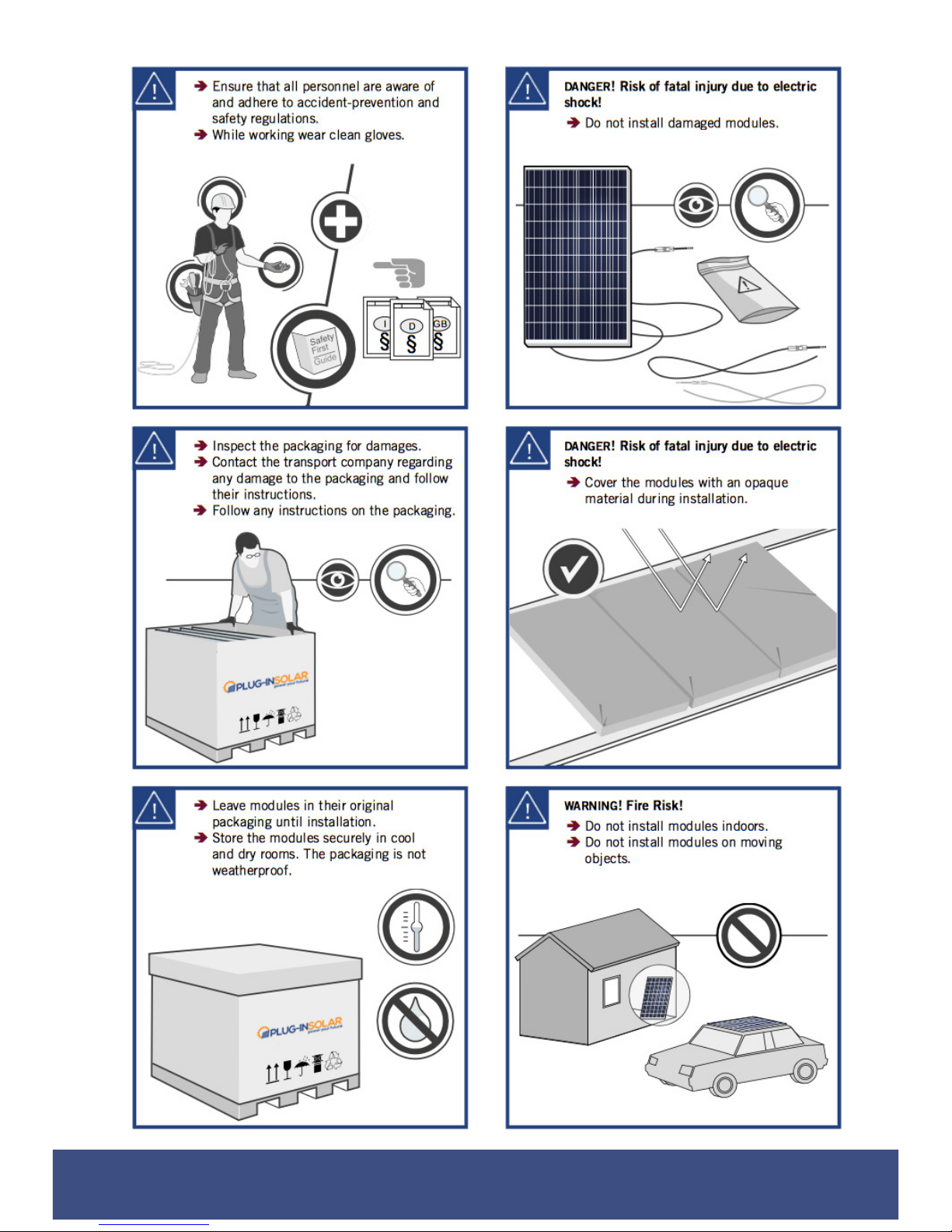
All appropriate health and safety regulations must be observed and required safety precautions
taken.
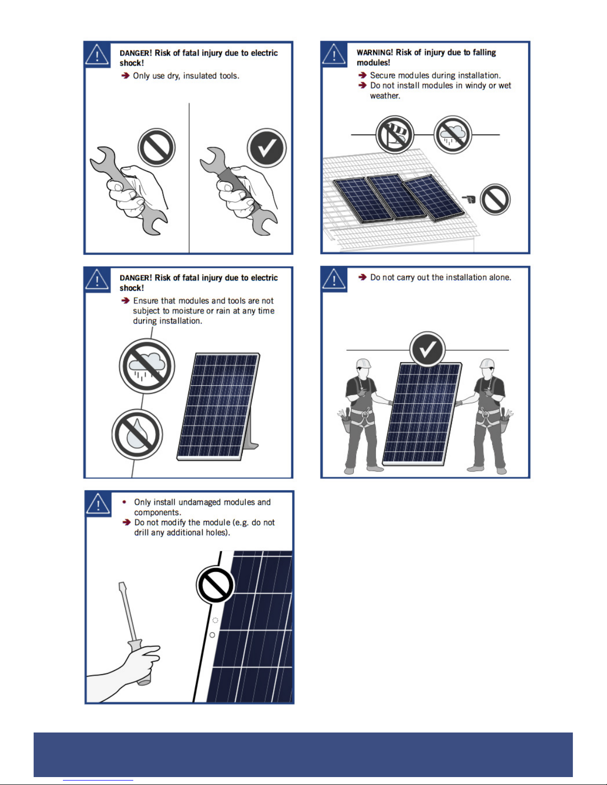
Be aware that installation of this equipment includes the risk of electric shock.
Be aware that the body of the Micro-Inverter is the heat sink and can reach a temperature of 80°C.
To reduce risk of burns, do not touch the body of the Micro-Inverter.
DO NOT disconnect the PV module from the Micro-Inverter without first disconnecting the AC
power. !In no circumstances, connect a DC input when an AC connector is unplugged.
DO NOT attempt to repair a Micro-Inverter. If it fails, contact Hoymiles Customer Support to
obtain an RMA number and start the replacement process. Damaging or opening a Micro-Inverter
will void the warranty.
CAUTION! !The external protective earthing conductor is connected to the micro-inverter
protective earthing terminal via an AC connector. !When connecting; connect the AC connectors
first to ensure the micro-inverter earthing then undertake the DC connections. When
disconnecting; disconnect the AC by opening the branch circuit breaker. Whilst maintaining the
protective earthing conductor in the branch circuit breaker, connect to the micro-inverter, then
disconnect the DC inputs. !
You MUST follow the IET Wiring Regulations at all times and consult a professional
electrician if you are in any doubt.

Plug-In Solar Ltd
289 London Road | Burgess Hill | West Sussex | RH15 9QU
www.pluginsolar.co.uk | info@pluginsolar.co.uk | 01444 672005 Page 6
WARNINGS
Never disconnect the DC wire connectors under load. Ensure that no current is
flowing in the DC wires prior to disconnecting. An opaque covering may be used to
cover the module prior to disconnecting the module.
Do not touch any live parts in the system, including the Solar array, when the
system has been connected to the electrical grid.
Prior to installing any of the Micro-Inverters, verify that the utility voltage at the
point of common connection matches the voltage rating on Micro-Inverter label.
Do not mount the Micro-Inverter in a location that allows exposure to direct
sunlight. Allow a minimum of 3/4’’(1.5cm.) between the roof and the bottom of the
Micro-Inverter to allow proper airflow.
Always disconnect AC power before disconnecting the PV module wires from the
Micro-Inverter. The AC connector of the first Micro-Inverter in a branch circuit is
suitable, as a disconnecting means, once the AC branch circuit breaker in the load
center has been opened.
The Micro-Inverter is powered by PV module DC power. Make sure you disconnect
and reconnect the DC connections to watch for the five short flashes.

Plug-In Solar Ltd
289 London Road | Burgess Hill | West Sussex | RH15 9QU
www.pluginsolar.co.uk | info@pluginsolar.co.uk | 01444 672005 Page 7
SOLAR PANEL INSTALLATION
When installing the solar panels included in your Plug-In Solar Kit, you must abide by a number of
safety requirements:
Do not operate solar panels near highly flammable gas !and vapors (e.g. gas tanks, gas stations).
!
Do not install solar panels in enclosed space. !
Do not install solar panels in locations where they may be !submerged in water.
!
Do not use solar panels as a substitute for normal !roofing (solar panels are not watertight).
Do not install solar panels in close proximity to air conditioning !systems.
Do not install solar panels above 4000 m (13120 ft) altitude !above sea level. !
Do not allow any chemical substance (e.g. oil, solvent !etc.) to come into contact with any part of
the solar panels.
The solar panel operating temperature must be between –40 °C to +85 °C (–40 °F to +185 °F).
Prevent solar panel shadowing. Optimal solar irradiation leads to maximum energy output. Install
the solar panels so that they face !the sun.
Avoid shadowing (due to objects such as buildings, !chimneys or trees).
Avoid partial shading (for example through overhead !lines, dirt, snow). !
Ensure you conform to the necessary structural requirements where you are installing the solar
panels. !
Ensure the solar panels are properly fastened to the ground, the roof, or the facade, using the
mounts provided.!
Ensure sufficient rear ventilation of the module.
!
Follow grounding procedures set out in the roof mount installation manual.
Please see the following instructions for further information on how to handle and install your solar
panels.
Refer to the Micro-Inverter installation section of this installation manual for information on how to
wire your solar panels to the Micro-Inverters.

Plug-In Solar Ltd
289 London Road | Burgess Hill | West Sussex | RH15 9QU
www.pluginsolar.co.uk | info@pluginsolar.co.uk | 01444 672005 Page 8

Plug-In Solar Ltd
289 London Road | Burgess Hill | West Sussex | RH15 9QU
www.pluginsolar.co.uk | info@pluginsolar.co.uk | 01444 672005 Page 9

Plug-In Solar Ltd
289 London Road | Burgess Hill | West Sussex | RH15 9QU
www.pluginsolar.co.uk | info@pluginsolar.co.uk | 01444 672005 Page 10

Plug-In Solar Ltd
289 London Road | Burgess Hill | West Sussex | RH15 9QU
www.pluginsolar.co.uk | info@pluginsolar.co.uk | 01444 672005 Page 11

Plug-In Solar Ltd
289 London Road | Burgess Hill | West Sussex | RH15 9QU
www.pluginsolar.co.uk | info@pluginsolar.co.uk | 01444 672005 Page 12
ADJUSTABLE GROUND MOUNT SYSTEM INSTALLATION
Important Notes before the installation of Adjustable Ground Mounts
1. The size of the mounting system (number of mounting triangles) should be specifically
calculated for each individual project, following the specified structural engineering standards
and regulations.
2. A prerequisite for proper application is a solid mounting base that can accommodate the
occurring forces (weight, wind and snow loads). ………………………………………
3. You MUST ballast your mounting system, especially in high wind areas. This can be done with
sandbags or similar (not supplied). For additional fixings to secure your grounds mounts to
concrete/metal or other material please contact us.
4. The installation instructions of the solar panel manufacturers must be adhered to.
5. When installing this product please observe the appropriate health and safety regulations and
take required safety precautions. This may include but is not limited to, gloves and goggles.
Plug-In Solar takes no responsibility for the method by which you choose to install your mounting
system. This is a guide only. Please consult a roofing expert if you are in any doubt on how to
safely and correctly install your system.
Adjustable Ground Mount System Components
Adjustable Metal Mounts
Solar Panel Clamps
SFS Screws
Bolts

Plug-In Solar Ltd
289 London Road | Burgess Hill | West Sussex | RH15 9QU
www.pluginsolar.co.uk | info@pluginsolar.co.uk | 01444 672005 Page 13
Adjustable Ground Mount Installation
1. Open a mounting triangle, and pull adjustable arm upwards. You can choose the angle at
which you install the panels for the best possible efficiency, by adjusting the support arm. You
will need your 13mm Spanner at this stage.

Plug-In Solar Ltd
289 London Road | Burgess Hill | West Sussex | RH15 9QU
www.pluginsolar.co.uk | info@pluginsolar.co.uk | 01444 672005 Page 14
2. Secure the Solar Panels to the Ground Mount system (using the nuts, bolts and SFS screws
provided). You will need your Hex key, Spanner and a drill with a masonry bit at this stage.
3. Continue this process until you have installed all the solar panels. Ensure all screws and
clamps are sufficiently tightened.
4. Remember to ballast your ground mount system accordingly, or use the mounting clips
(available on request) shown below to secure the frames to a concrete base. Please contact us
if you need any further information on the amount of ballast required.

Plug-In Solar Ltd
289 London Road | Burgess Hill | West Sussex | RH15 9QU
www.pluginsolar.co.uk | info@pluginsolar.co.uk | 01444 672005 Page 15
MICRO-INVERTER INSTALLATION
1. System Wiring Diagram
2. Once you have completed installing the Adjustable Metal Mount system, use the SFS (self
drilling) screws provided to affix the Micro-Inverter to the upper arm of the Metal Mounts. See
image below for guidance.
Each Micro-Inverter has serial number labels affixed. Once the micro-inverters are installed, please
peel one label off each micro-inverter and stick them to the warranty card (please refer to the
‘Completing Your Warranty Card’ section of this installation manual for more information).

Plug-In Solar Ltd
289 London Road | Burgess Hill | West Sussex | RH15 9QU
www.pluginsolar.co.uk | info@pluginsolar.co.uk | 01444 672005 Page 16
3. Connect the Micro-Inverters to the AC Bus Trunk Cable
Plug the AC connector of the first Micro-Inverter into the connector of the next Micro-Inverter, and
so forth, to form a continuous AC branch circuit. Do this for each Micro-Inverter in your system.
Ensure a click is heard as connectors engage. Ensure that all connections are properly closed.
WARNIING: Do NOT exceed a maximum of (5) five Micro-Inverters in an AC branch circuit when
using the Plug-In Solar System.
Install the End Cap on the open AC connector of the last Micro-Inverter in the AC branch circuit.
Ensure a click is heard as connectors engage. Ensure that all connections are properly closed.

Plug-In Solar Ltd
289 London Road | Burgess Hill | West Sussex | RH15 9QU
www.pluginsolar.co.uk | info@pluginsolar.co.uk | 01444 672005 Page 17
4. Connect Micro Inverters to Solar Panels (PV Modules)
Connect each Solar Panel to the Micro-Inverter DC cables to feed PV power into the Micro
inverter, following the polarity direction marked on each Micro inverter. Ensure a click is heard as
connectors engage.
When plugging in the DC cables, the Micro-Inverter should immediately blink green three times.
This will happen as soon as the cables are plugged in and will show that the Micro-Inverter is
functioning correctly. This entire check function will start and end within 5 seconds of plugging in
the unit, so pay careful attention to these lights when connecting the DC cables.
WARNING: Ensure that all AC and DC wiring is correct. Ensure that none of the AC and DC wires
are pinched or damaged. Ensure that all connections are properly closed.
WARNING: If you are installing an odd number of Solar panels, ensure you use the MC4 sealing
caps provided with your kit to seal the exposed MC4 connectors on the Micro-Inverter.

Plug-In Solar Ltd
289 London Road | Burgess Hill | West Sussex | RH15 9QU
www.pluginsolar.co.uk | info@pluginsolar.co.uk | 01444 672005 Page 18
5. If you need to extend the length of AC Bus Trunk Cable, we can supply extra lengths on
request. If you provide your own cable please be sure to use the correct cable wire size (AWG)
depending on distance of the last Micro-Inverter to the connection point and the number of
Micro-Inverters in the branch, as shown in the table below. Please be aware, the longer the
cable run, the greater the power loss.
Follow the instructions outlined below to connect the APS AC Bus Trunk Cable to your extension
cable, using a connection box, or similar (supplied upon request).

Plug-In Solar Ltd
289 London Road | Burgess Hill | West Sussex | RH15 9QU
www.pluginsolar.co.uk | info@pluginsolar.co.uk | 01444 672005 Page 19
WIRING THE SOLAR TO THE EXISITING MAINS CIRCUIT
IMPORTANT SAFETY INFORMATION – FOR YOUR PROTECTION
Before installation please read these instructions carefully and use the Plug-In Solar Connection Unit in
accordance with these safety wiring instructions.
In older houses, you may find a variety of old fuse boxes where the mains supply comes in. You may also
have wiring and fittings of an older style. These may not be up to the standard required today. If this is the
case, have it all checked and tested by a professional electrician BEFORE carrying out any work on it.
Some old installations may now be dangerous.
Electricity is dangerous. Always disconnect from mains supply before any inspection or repair to equipment.
Safety must always be given top priority. Do not allow children to tamper with electrical devices.
ALWAYS FOLLOW THE IET WIRING REGULATIONS.
You must NOT install the Plug-In Solar Connection Unit in the following locations as set out by Part P:
(a) within a room containing a bath or shower, the space surrounding a bath tap or shower head,
where the space extends —
(i) vertically from the finished floor level to —
(aa) a height of 2.25 metres; or
(bb) the position of the shower head where it is attached to a wall or ceiling at a point
higher than 2.25 metres from that level; and
(ii) horizontally —
(aa) where there is a bath tub or shower tray, from the edge of the bathtub or shower
tray to a distance of 0.6 metres; or
(bb) where there is no bath tub or shower tray, from the centre point of the shower
head where it is attached to the wall or ceiling to a distance of 1.2 metres; or
(b) a room containing a swimming pool or sauna heater.
As an additional precaution, wear rubber-soled shoes. This will provide a measure of insulation between you
and the ground!
IF YOU ARE NOT ABSOLUTELY CERTAIN ABOUT ANY ASPECT OF ELECTRICAL WORK, SEEK PROFESSIONAL ADVICE
1.1. Switch off the power and remove the fuse for the relevant circuit before carrying out any
work, or inspecting, either it, or the appliances connected to it. Never inspect, or carry out work
on, any part of the system with the power on. Make sure that power cannot be inadvertently
restored by someone else.
1.2. Use a voltage tester to check the power to the wires or connections are off before touching
them.

Plug-In Solar Ltd
289 London Road | Burgess Hill | West Sussex | RH15 9QU
www.pluginsolar.co.uk | info@pluginsolar.co.uk | 01444 672005 Page 20
1.3. Once the power is disconnected, wire the Plug-In Solar Connection Unit using the following
instructions.
Wire Identification (if in doubt consult a qualified electrician)
EARTH – Green and Yellow Sleeving
LIVE – Red or Brown
NEUTRAL – Blue or Black
a) If using the Plug-In Solar Connection Unit to replace an old socket (or similar), note the cable
connections and wire up the Plug-In Solar Connection Unit the same way as the replaced item, with
earthing as stated in these instructions.
b) Route the cable through the appropriate entry point of the mounting box (this is usually at the rear).
c) Cables should be prepared so sufficient conductor length reaches the terminals. Strip the ends of
the individual conductors so that an adequate length enters the terminals.
d) Carefully arrange the wiring to lie along the edges of the product or box, keeping the central area
clear.
e) Wire the Plug-In Solar Connection Unit using the following diagram (a larger version can be found in
Appendix 1):
f) When connecting the Plug-In Solar Connection Unit ensure that only the bare end of the wire enters
the terminal, and no bare wires are visible. Always tighten the terminal screws, but don’t over
tighten. An earth connection should always be made between the mounting box earth terminal and
the fused connection unit terminal. If the earth wire is bare, it must be sleeved with appropriate
green/yellow sleeving.
g) If you are in any doubt about connecting this product consult a qualified electrician.
1.4. Wiring insulation tests should be completed to avoid misleading instrument readings and
possible internal damage to the unit. Check your work thoroughly before restoring power to the
circuit. If you are not certain, seek professional advice.
1.5. Once power has been restored, after around a two minute initialisation time, your Plug-In
Solar kit will be feeding FREE electricity into your mains circuit.
Table of contents
Popular Inverter manuals by other brands

SolrenView
SolrenView PVI 23TL installation guide

SMA
SMA SUNNY TRIPOWER 5000TL Replacement manual

SOLIS
SOLIS S6-EH1P3.8K-H-US user manual

BOLERO
BOLERO SEAP-12-800 Operation and installation manual

DAB PUMPS
DAB PUMPS MCE-22/P Instruction for installation and maintenance

Motech
Motech FG 700F Series operating manual