Plymovent FAN-28 User manual

www.plymovent.com
Extraction fan
FAN-28
Installation and user manualEN

0507210010/010320/D FAN-28 1
PREFACE...................................................................................................................................2
1 INTRODUCTION..........................................................................................................2
2 PRODUCT DESCRIPTION .............................................................................................3
3 SAFETY INSTRUCTIONS ..............................................................................................3
4 INSTALLATION ........................................................................................................... 4
5 USE ...........................................................................................................................5
6 MAINTENANCE ...........................................................................................................5
7 TROUBLESHOOTING ...................................................................................................5
8 SPARE PARTS .............................................................................................................6
9 DISPOSAL ..................................................................................................................6
CE DECLARATION......................................................................................................................6
EN | ORIGINAL INSTRUCTION
All rights reserved. The information given in this document has been collected for the general convenience of our clients. It has been based on general data pertaining to construction material
properties and working methods known to us at the time of issue of the document and is therefore subject at any time to change or amendment and the right to change or amend is hereby expressly
reserved. The instructions in this publication only serve as a guideline for installation, use, maintenance and repair of the product mentioned on the cover page of this document. This publication is to
be used for the standard model of the product of the type given on the cover page. Thus the manufacturer cannot be held responsible for any damage resulting from the application of this publication
to the version actually delivered to you. This publication has been written with great care. However, the manufacturer cannot be held responsible, either for any errors occurring in this publication or
for their consequences.
To improve comprehension for people whose rst language is not English, we have written parts of this manual in Simplied Technical English (STE). STE is a controlled language
originally developed for aerospace industry maintenance manuals. It offers a carefully limited and standardized subset of English, along with specic writing rules.
TABLE OF CONTENTS

0507210010/010320/D FAN-28 2
PREFACE
Using this manual
This manual is intended to be used as a work of reference for
professional, well trained and authorised users to be able to
safely install, use, maintain and repair the product mentioned
on the cover of this document.
Pictograms and symbols
The following pictograms and symbols are used in this manual:
TIP
Suggestions and recommendations to simplify
carrying out tasks and actions.
ATTENTION
A remark with additional information for the user. A
remark brings possible problems to the user’s
attention.
WARNING!
Procedures which, if not carried out with the
necessary caution, may damage the product or
cause serious personal injury.
CAUTION!
Denotes risk of electric shock.
WARNING!
Fire hazard! Important warning to prevent re.
Personal protective equipment (PPE)
Instruction to use respiratory protection when you
do service, maintenance and repair jobs, as well as
during functional testing. We recommend to use a
half-face respirator according to EN 149:2001 +
A1:2009, class FFP3 (Directive 89/686/EEC).
Personal protective equipment (PPE)
Instruction to use protective gloves when you do
service, maintenance and repair jobs.
Text indicators
Listings indicated by “-” (hyphen) concern enumerations.
Listings indicated by “•” (bullet point) describe steps to
perform.
Service and technical support
For information about specic adjustments, maintenance or
repair jobs which are not dealt with in this manual, please
contact the supplier of the product. He will always be willing to
help you. Make sure you have the following specications at
hand:
- product name
- serial number
You can nd these data on the identication plate.
1 INTRODUCTION
1.1 Identication of the product
The identication plate contains, among other
things, the following data:
- product name
- serial number
- supply voltage and frequency
- power consumption
1.2 General description
The FAN-28 is an extraction fan that is especially designed to
remove welding fumes and gases that are released during the
most common welding processes.
The fan is intended and designed for use with extraction arms
and lter units.
1.3 Product combinations
1.3.1 Extraction arms and mounting brackets
You can use the FAN-28 in congurations with an extraction
arm of Plymovent. The table below shows which type of
additional mounting brackets you need in a specic
conguration.
Connection to Mounting brackets
Extraction arm
T-Flex TNB
T-Flex/CW No additional
brackets required
Flex-2 TNB
Flex-3 | Flex-4 NMB
UltraFlex-3 | UltraFlex-4 NMB
UltraFlex-4/LC NMB
NEC-2 | NEC-4 TNB
Other
Duct connection TNB
1.3.2 Control equipment
Manual switch on/o, wall-mounted:
- MPS range | Motor protection switch; specic type depening
on the connection voltage
In congurations of an extraction arm with WL (working light),
WL-AST (working light + automatic start/stop) and WCS
(welding cable sensor), you must install a thermal relay (NTR
range) in the control box (CB); the specic type depending on
the connection voltage.
1.4 Options and accessories
The following products can be obtained as an option and/or
accessory:
- SAS-160 | Duct silencer Ø 160 mm
- CKS | Connection kit (exible hose 1 m / Ø 160 mm + two
hose clamps)
1.5 Technical specications
Physical dimensions and properties
Fan type radial
Inlet diameter Ø 200 mm (Ø 7.87 in.)
Outlet diameter Ø 160 mm (Ø 6.30 in.)
Weight 15 kg (33 lbs.)
Performance
Unrestricted airow 2400 m3/h (1413 CFM)
Speed:
- 50 Hz
- 60 Hz
2800 rpm
3400 rpm
Noise level 69 dB(A) according to ISO 3746
Electrical data
Power consumption 0,75 kW (1 HP)
Available connection
voltages
115V/1~/50Hz | 120V/1~/60Hz
230V/1~/50Hz | 230V/1~/60Hz
230V/3~/50Hz | 400V/3~/50Hz
400V/3~/60Hz
Max. start/stops per hour 30
Insulation class F

0507210010/010320/D FAN-28 3
Refer to the available product data sheets for
detailed product specications.
1.6 Dimensions
Refer to Fig. I on page 7.
1.7 Pressure drop
Refer to Fig. II on page 7.
1.8 Ambient conditions
Min. operating temperature 5°C (41°F)
Nom. operating temperature 20°C (68°F)
Max. operating temperature 40°C (104°F)
Max. relative humidity 80%
2 PRODUCT DESCRIPTION
2.1 Components
The product consists of the following main components:
Fig. 2.1
A Motor
B Outlet opening
C Fan housing
D Fan wheel
E Inlet opening
Fig. 2.1
A
B
C
D
E
Main components
2.2 Operation
The FAN-28 fan has been designed for extracting welding
fumes and gases that are released during the most common
welding processes.
The air is extracted through the inlet opening and exhausted
via the outlet openning.
The fans are suitable for connection to:
- an extraction arm or crane
- a lter system
2.2.1 Control equipment
Plymovent provides various control equipment to control the
fan. Refer to the section 1.3.2 for more information.
3 SAFETY INSTRUCTIONS
General
The manufacturer does not accept any liability for
damage to the product or personal injury caused by
ignoring of the safety instructions in this manual, or
by negligence during installation, use, maintenance, and repair
of the product mentioned on the cover of this document and
any corresponding accessories.
Specic working conditions or used accessories may require
additional safety instructions. Immediately contact your
supplier if you detect a potential danger when using the
product.
The user of the product is always fully responsible for
observing the local safety instructions and regulations.
Observe all applicable safety instructions and
regulations.
User manual
- Everyone working on or with the product, must be familiar
with the contents of this manual and must strictly observe
the instructions therein. The management should instruct the
personnel in accordance with the manual and observe all
instructions and directions given.
- Do not change the order of the steps to perform.
- Keep the manual with the product.
Users
The use of this product is exclusively reserved to authorised,
trained and qualied users. Temporary personnel and
personnel in training can only use the product under
supervision and responsibility of skilled engineers.
Intended use1
The product has been designed exclusively for extracting gases
and particles which are released during the most common
welding processes and for extracting vehicle exhaust gases.
Using the product for other purposes is considered contrary to
its intended use. The manufacturer accepts no liability for any
damage or injury resulting from such use. The product has
been built in accordance with state-of-the-art standards and
recognised safety regulations. Only use this product when in
technically perfect condition in accordance with its intended
use and the instructions explained in the user manual.
Technical specications
Do not change the specications given in this manual.
Modications
Modication of (parts of) the product is not allowed.
Installation
- The installation of this product is exclusively reserved to
authorised, trained and qualied engineers.
- The electric connection must be executed in accordance with
the local codes and requirements. Ensure compliance with
the EMC regulatory arrangements.
- During installation, always use Personal Protective
Equipment (PPE) to avoid injury. This also applies to persons
who enter the work area during installation.
- Use sucient climbing gear and safety guards when working
on a higher level than 2 metres (local restrictions may
apply).
1. “Intended use” as explained in EN-ISO 12100-1 is the use for which the
technical product is suited as specied by the manufacturer, inclusive of his
directions in the sales brochure. In case of doubt it is the use which can be
deduced from the construction, the model and the function of the technical
product which is considered normal use. Operating the machine within the
limits of its intended use also involves observing the instructions in the user
manual.

0507210010/010320/D FAN-28 4
- Do not install the product in front of entrances and exits that
must be used for emergency services.
- Mind any gas and water pipes and electric cables.
- Make sure that the workspace is well illuminated.
- Stay alert and keep your attention to your work. Do not
install the product when you are under the inuence of
drugs, alcohol or medicine.
- Air containing particles such as chromium, nickel, beryllium,
cadmium, lead etc., should never be recycled. This air must
always be brought outside the working area.
Use
WARNING!
Fire hazard! Do not use the product for:
- polishing applications in combination with
grinding, welding or any other application that
generate sparks (bers from polishing or abrasive ap disks
are highly ammable and pose a high risk of lter res when
exposed to sparks)
- arc-air gouging
- extracting ammable, glowing or burning particles
or solids or liquids
- extracting of aggressive fumes (such as
hydrochloric acid) or sharp particles
- extracting dust particles that are released when
welding surfaces treated with primer
- sucking cigarettes, cigars, oiled tissues, and other
burning particles, objects, and acids
WARNING!
Explosion hazard! Do not use the product for
explosion-hazardous applications, e.g.:
- aluminium laser cutting
- grinding aluminium and magnesium
- explosive environments or explosive substances/
gases
WARNING!
Do not use the product for:
- extraction of hot gases (more than 70°C/158°F
continuously)
- ame spraying
- oil mist
- heavy oil mist in welding fume
- extraction of cement, saw dust, wood dust etc.
- Inspect the product and check it for damage. Verify the
functioning of the safety features.
- During use, always use Personal Protective Equipment (PPE)
to avoid injury. This also applies for persons who enter the
work area.
- Check the working environment. Do not allow unauthorised
persons to enter the working environment.
- Protect the product against water and humidity.
- Make sure the room is always suciently ventilated; this
applies especially to conned spaces.
- Make sure that the workshop, in the vicinity of the product,
contains sucient approved re extinguishers (suitable for
re classes ABC).
- Do not leave any tools or other objects in or on the unit.
Service, maintenance and repairs
- Always use Personal Protective Equipment (PPE) to avoid
injury. This also applies for persons who enter the work area.
- Do not leave any tools in or on the product.
- Use sucient climbing gear and safety guards when working
on a higher level than 2 metres (local restrictions may
apply).
ATTENTION
Fully disconnect the fan from the main before you
carry out service, maintenance and/or repair jobs.
Personal protective equipment (PPE)
Wear respiratory protection and protective
gloves during service, maintenance and
repairs.
4 INSTALLATION
4.1 Tools and requirements
You need the following tools and requirements to
install the fan:
- basic tools
- electrical tools
4.1.1 To be sourced locally
- Hardware to install the mounting brackets
NMB or TNB
- Mains cord
4.2 Unpacking
Make sure that the product is complete. The
package contains:
- extraction fan
- mounting material to install the fan on the wall brackets NMB
or TNB
4.3 Mounting
The mounting instructions of the fan depend on the selected
wall bracket.
In case of mounting brackets type NMB, proceed with
paragraph 4.3.1.
In case of mounting brackets type TNB, proceed with
paragraph 4.3.2.
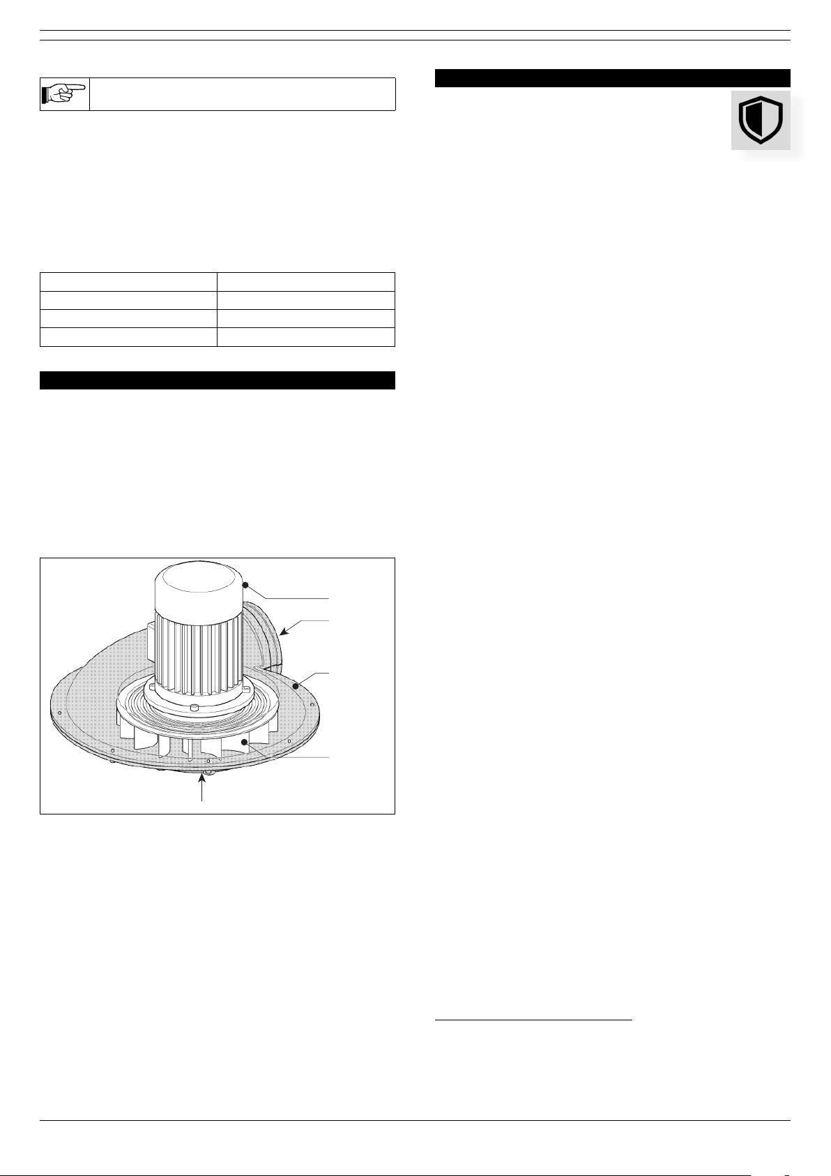
4.3.1 Mounting brackets NMB
Fig. 4.1
• Install the NMB as described in the corresponding manual.
• Instal the extraction arm as described in the corresponding
manual.
• Install the fan (B) on the rotating ange (C) of the
extraction arm with the supplied mounting material.
• Tighten the bolts rmly.
• Make sure that the seal between the conection ange and
the fan is airtight.
Subsequently:
• Connect the outlet opening (A) of the fan to:
- a spiral tube (Ø 160 mm); or
- a exible hose Ø 160 mm (CKS; ref. paragraph 1.4)
• Make sure that all connections are airtight.

0507210010/010320/D FAN-28 5
Fig. 4.1 Installation on NMB
4.3.2 Mounting brackets TNB
Fig. 4.2
• Install the TNB, including the connection ange (C), as
described in the corresponding manual.
• Install the extraction arm on the connection ange, as
described in the corresponding manual.
• Install the fan (B) on the connection ange (C) with the
supplied mounting material.
• Tighten the bolts rmly.
• Make sure that the seal between the conection ange and
the fan is airtight.
Subsequently:
• Connect the outlet opening (A) of the fan to:
- a spiral tube (Ø 160 mm); or
- a exible hose Ø 160 mm (CKS; ref. paragraph 1.4)
• Make sure that all connections are airtight.
In case the fan is connected to an extension crane
(NEC), you must use the hose clamp (E) that is
supplied with the crane.
Fig. 4.2 Installation on TNB
4.4 Electric connection
CAUTION!
Make sure that the fan is suitable for connection to
the local mains. You can nd information about the
connection voltage and frequency on the
identication plate.
4.4.1 Mains cord
• Install a mains cord to the fan in accordance with the local
requirements.
4.4.2 Control equipment
You can connect the fan via a control box (CB) or a motor
protection switch (MPS).
To connect the control equipment, do the following.
• Connect the fan to the selected control equipment in
accordance with the information on the identication plate
on the motor.
• Connect the control equipment to the mains according to
the separately supplied electrical diagram.
An arrow on the fan housing indicates the correct direction of
rotation of the motor. The rotation is visible through the grid of
the motor.
CAUTION
Be careful with rotating parts. Keep your hands and
other objects away from the inlet opening of the
fan.
• Make sure that the direction of rotation of the motor is
correct.
• If necessary, invert the connection of the phases.
5 USE
Refer to the documentation supplied with the selected control
equipment how to control the fan.
6 MAINTENANCE
The indicated maintenance intervals can vary
depending on the specic working and ambient
conditions. Therefore we recommend to thoroughly
inspect the complete product once every year
beside the indicated periodic maintenance. For this
purpose contact your supplier.
The maintenance activities in the table below indicated by [1]
can be carried out by the user; other activities are strictly
reserved for well-trained and authorised service engineers.
Component Action Frequency:
every 12
months
Outside Check the fan for damages X [1]
Clean it with a non-aggressive
detergent X [1]
Inside Check the fan and fan housing for
incrusted particles. Clean if
necessary
X [1]
Sealing
material
Check for damage. Replace if
necessary X [1]
7 TROUBLESHOOTING
If the fan does not function (correctly), consult the
checklist below to see if you can remedy the error
yourself. Should this not be possible, contact your
supplier.

0507210010/010320/D FAN-28 6
WARNING
When you carry out the activities below:
- rst de-energize the fan
- obey the safety regulations that are written in
chapter 3
Symptom Problem Possible
cause
Solution
The motor
does not start
The fan does
not function
No mains
voltage
Connect the mains
voltage
The mains cord
is defective
Repair or replace
the mains cord
Loose contacts Repair the contacts
Motor
protection
switch (MPS)
defective
Replace the motor
protection switch
Control box
(CB) defective
Repair or replace
the CB
Motor defective Repair or replace
the motor
The fan
makes a
humming
sound, but
does not run
Extraction
capacity
insucient or
no extraction
at all
Motor uses 2
phases instead
of 3 (3ph motor
only)
Repair the phase
connection
Motor capacitor
defective or not
connected (1ph
motor only)
Connect or replace
the motor capacitor
Motor stops
automatically
The fan does
not function
Motor
protection
switch (MPS) is
activated
Let the motor cool
down for some time
Inverted
direction of
rotation of the
motor (3ph
motor only)
Change the
direction of rotation
Motor defective Repair or replace
the motor
Poor
extraction
capacity
The fan does
not function
properly
Inverted
direction of
rotation of the
motor (3ph
motor only)
Change the
direction of rotation
Motor defective Repair or replace
the motor
The fan is
polluted
Clean the fan
blades
Extraction of
false air
Damaged or
worn sealing
material
Replace the sealing
material
Vibrations in
the fan
Fan is not
steady
Imbalance in
the fan
Clean the fan
blades
8 SPARE PARTS
The following spare parts are available for the fan;
- refer to exploded view Fig. III on page 7
9 DISPOSAL
After the life of the product, dispose it of in
accordance with federal, state or local regulations.
CE DECLARATION
CE declaration of conformity for machinery
We, Plymovent Manufacturing B.V., Koraalstraat 9,
1812 RK Alkmaar, Netherlands, herewith declare, on
our own responsibility, that the product:
- FAN-28
which this declaration refers to, is in accordance with the
conditions of the following Directives:
- Machine Directive 2006/42 EC
- EMC 2014/30 EU
- LVD 2014/35 EU
- ErP Directive 2009/125 EC
Signature:
Name: M.S.J. Ligthart
Position: Product Manager
Date of issue: 1st April 2020
An installation is dened as a combination of several nished products
or components that are assembled by an installer at a given place. The
various parts of the installation are intended to operate together in a
particular environment and to perform a specic task. The entire
installation must comply with the relevant directives and standards. The
assembly instructions given by the manufacturer, as well as the whole
method of installation, must be in accordance with good engineering
practices within the context of installations, as well as installation rules.
Considering the above, the installer will be responsible for completing
the installation and issuing the nal CE Declaration of Conformity.

0507210010/010320/D FAN-28 7
ANNEX
Fig. I Dimensions
A B
D
CE
FGIJ
H
mm inch
A 250 9.84
B 230 9.06
C 130 5.12
D 160 6.30
E 167 6.57
F 275 10.83
G 225 8.86
HØ 160 Ø 6.30
I 300 11.81
J 70 2.75
Fig. II Pressure drop
0
200
400
600
800
1000
1200
1400
1600
1800
Y
0 200 400 600 800 1000 1200 1400 1600 1800 2000
X
X = Airow (m3/h)
Y = Static pressure (Pa)
Fig. III Spare parts
9820080040
0320000100
0321012030
0000102291
0000102305
0612010220
0000102306
0000102297
0708020150
Art. no. Description
General
0000102291 Sealing ring
0000102297 Aluminium fan wheel 50Hz
0000102305 Housing FAN-14/28/MNF/mobile units, motor
side
0000102306 Housing FAN-14/28/MNF, suction side
0612010220 Adjusting ring 19x1
0708020150 Aluminium fan wheel 60Hz
9820080040 Sealing set FAN 14/28/MNF
FAN-28 (400V/3ph/50Hz)
0320000100 Motor 0,75 kW, 230-400V/3ph/50-60Hz
FAN-28 (230V/3ph/50Hz)
0320000100 Motor 0,75 kW, 230-400V/3ph/50-60Hz
FAN-28 (230V/1ph/50Hz)
0321012030 Motor 0,75kW, 115-230V/1ph/50-60Hz
FAN-28 (115V/1ph/50Hz)
0321012030 Motor 0,75kW, 115-230V/1ph/50-60Hz

www.plymovent.com
0507210010/010320/D FAN-28
Table of contents
Other Plymovent Fan manuals

Plymovent
Plymovent TEV Series User manual

Plymovent
Plymovent SIF-700 User manual

Plymovent
Plymovent MDB-Compact PRO Series User manual

Plymovent
Plymovent FUA-1300 User manual

Plymovent
Plymovent SBT-Pneumatic SBTP-6-100-160 Operational manual

Plymovent
Plymovent FUA-1300 User manual

Plymovent
Plymovent TEV User manual

Plymovent
Plymovent FUA-1300 User manual

Plymovent
Plymovent TEV-385 User manual