pm-tools PM LIFT Extended Product information sheet

1.Introduction 1
1.1 Execution 1
1.2 Information about this manual 2
2. Safety 3
2.1 Warnings 4
2.2 Hazard sign 4
2.3 Other symbols 5
2.4 User limitations 5
2.5 Device description 5
2.6 Intended use 6
2.7 Safety devices 7
2.8 Regular inspection of the lift 7
2.9 Accident prevention regulations 7
2.10 Declaration of conformity 8
3. Delivery 9
3.1 Main components of the lift 10
3.2 Main components of the foot pedal controller 11
4. Assembly and installation 12
4.1 Foundation 12
4.2 Operation of the lift 13
4.3 Before the first start-up 14
4.4 Connecting the foot pedal controller 15
4.5 Filling with hydraulic oil / Checking the oil level 17
4.6 Support arms adjustment 18
5. Lift operation 19
5.1 Positioning vehicles on the lift 19
5.2 Raising and lowering the vehicle 20
6. Maintenance and care 23
6.1 Maintenance schedule 23
pm-tools, Małorolnych 10B, PL-66-400 Gorzów Wielkopolski,www.pmtools.pl

7. Troubleshooting / Malfunctions 24
8. Technical data 25
8.1 Hydraulic and pneumatic diagram 25
8.2 Spare parts list 26
9. Waste disposal and environmental protection 26
10. List of figures 27
11. List of tables 27
12. Inspection log with templates 28
12.1 Inspection review 29
12.2 Main sheet 30
12.3 General arrangement drawing 31
12.4 First start-up 32
12.5 Regular safety check 34
12.6 Extraordinary security check 36
pm-tools, Małorolnych 10B, PL-66-400 Gorzów Wielkopolski,www.pmtools.pl

1 of 39pages
1.
Introduction
Thank you for the trust you have placed in our vehicle lift.
You have purchased a very high quality product. It has been very carefully
designed and built by our company.
However, if you are not satisfied with something do not hesitate to contact
us.
PM-Tools
Małorolnych 10B
PL-66-400 Gorzów Wielkopolski
Mobile:+48-501382847
Mail: info@pmtools.pl
www.pmtools.pl
We speak Polish, German and English.
We wish you a lot of satisfaction with operation of your vehicle lift.
1.1
Execution
This user's manual is valid for the PM Extended lift.
An external compressed air supply of 6-7 bar is required for operation of
the lift.
Fig. 1: Rating plate
The exact model designation, serial
number and year of manufacture can
be found on the rating plate on the
base frame (Fig. 1). More
information can also be found in the
Declaration of Conformity in section
2.10.
pm-tools, Małorolnych 10B, PL-66-400 Gorzów Wielkopolski,www.pmtools.pl

2 of 39pages
1.2
Information about this manual
Read this manual carefully before using the lift for the first time. In this
way, malfunctions and defects caused by incorrect or improper use can be
avoided.
The user's manual contains:
•
Important safety regulations
•
Hints on operation of the lift
•
Instructions for maintenance and care of the lift
•
Assistance in troubleshooting
•
Review of our accessories
•
Review the necessary tests in the inspection log
This user's manual describes the proper use of the lift. Therefore, it should
be kept near the lift for quick reference. User's manual is part of the lift
and should be handed over to new owner with the inspection log in the
event of sale or further commissioning.
Remember to follow all safety instructions. These can be found in the
Safety section.
Furthermore, safety instructions are repeated at appropriate places in the
user's manual. The user is responsible for following all safety regulations in
all cases. All safety regulations are in accordance with applicable European
Union directives and regulations. Furthermore, additional national
regulations may require to be considered.
The national regulations and laws of the given country shall apply while
using the lift outside the European Union. Depending on area of use it is
also required to consider the national regulations and laws. Please note
that safe operation of the lift is guaranteed only if the original spare parts
are used.
pm-tools, Małorolnych 10B, PL-66-400 Gorzów Wielkopolski,www.pmtools.pl

3 of 39pages
2.
Safety
The lift can only be used after you have thoroughly read and understood
these manual. Unauthorized modifications in the lift and its safety devices
are prohibited. PM-Tools shall not be responsible for any damages resulting
from violating of this regulations.
The following hints should be observed:
•
Risk of crushing.
•
Use personal protection equipment.
•
Observe all accident prevention regulations.
•
We recommend to create a 3-meter safety zone around the lift.
•
Make sure that the lift does not obstruct the exit paths. This is especially
important when the vehicle is placed on a lift.
•
Make sure that there are during the lifting and lowering of the lift there
are no dangerous situations in the safety zone. If this happens, stop the
lift immediately and remedy the cause of the dangerous situation.
Dangerous situations can include people or animals staying in the safety
zone of the lift.
•
Make sure there are no objects under the lift when it is raised.
•
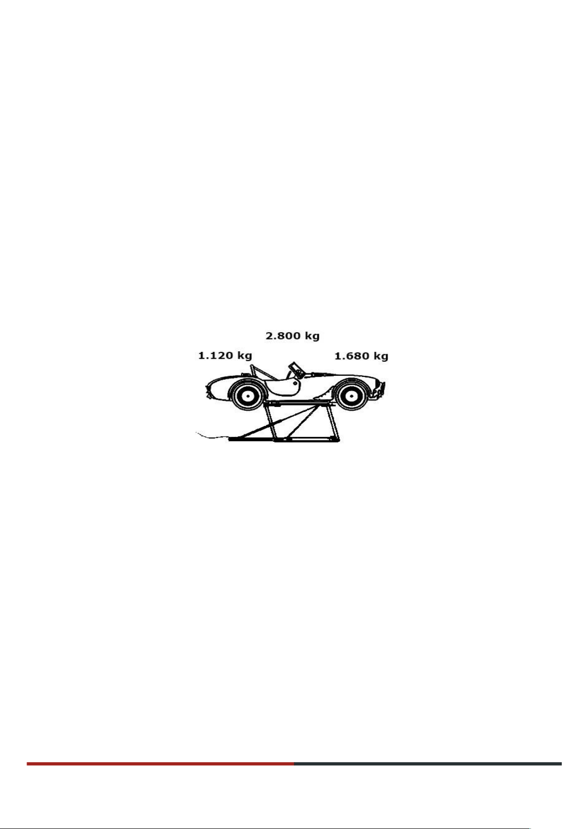
Do not exceed the permissible load capacity. Observe the information
given on the rating plate.
•
Make sure that vehicle weight and load distribution in lifting points
conform to the recommendations given in this user's manual.
•
Make sure that disassembly of the vehicle parts will not cause shifting of
the load/centre of gravity so that the required limits are no longer
observed.
•
Secure the lift in lifted position lifting it only to the next safety catch and
installing the pin lock using a safety pin.
•
Depressurize the lift in case of failure or during maintenance and repair
works. To depressurize the lift, disconnect the air hose from the
connector.
•
Check for leaking hydraulic hoses.
•
Only original spare parts should be used.
pm-tools, Małorolnych 10B, PL-66-400 Gorzów Wielkopolski,www.pmtools.pl

4 of 39pages
2.1
Warnings
DANGER
This information alerts you about dangerous situation. Failure to observe
this information could result in death or serious injury.
WARNING
This information alerts you about dangerous situation. Failure to follow this
information may result in death or serious injury.
CAUTION
This information alerts you about dangerous situation. Failure to
observe this information may result in moderate or minor injury.
2.2
Hazard sign
NOTE
This information warns of environmental pollution. Spills
may cause short- or long-term damages to the environment.
Never dispose of into sewage or with household waste.
pm-tools, Małorolnych 10B, PL-66-400 Gorzów Wielkopolski,www.pmtools.pl

5 of 39pages
2.3
Other symbols
HINT
Wear protective glasses.
This protects against eye injuries.
NOTE
This information warns of a possible situation that could
cause property damage if not avoided.
2.4
User limitations
Only person who are 18 years of age or older may be employed to operate
the lifts alone. Operators should be trained within the scope of operation of
the lift and should prove their competences to their employer. They should
receive clear instructions from the employer
regarding operation of the lift. Lift operation instruction should be given in
writing. By-standers should not stay near the lift.
2.5
Device description
PM Extended lift is intended for lifting of the vehicles (passenger cars and
small trucks) to the height of approx. 100 cm using hydraulic-pneumatic
control. Vehicle wheels are unloaded during lifting (free standing).
pm-tools, Małorolnych 10B, PL-66-400 Gorzów Wielkopolski,www.pmtools.pl

6 of 39pages
2.6
Intended use
PM Extended lift is used only for lifting of the mechanical vehicles. The
vehicles must meet the following conditions:
•
The total weight of the vehicle should not exceed 2800 kg.
•
The minimum distance between lifting points (wheel track) must be 110
cm. If this distance is shorter, as for classic cars, the load
capacity will be reduced. If this is the case, please contact us before
using the lift.
•
The minimum distance between the lifting points (wheel base) must be
175 cm.
•
In general, the vehicles should be lifted only in the longitudinal
direction.
•
Vehicle load distribution should be balanced or ensured in a ratio not
less than 2:3 or not exceeding 3:2.
•
it is recommended to position the vehicles so that the hydraulic
actuator is facing towards the engine. (Fig. 2)
Fig. 2: Recommended load distribution
The PM Extended lift can lift a vehicle by approx. 100 cm allowing works
under the vehicle, e.g. on wheels, brakes, shock absorbers or bodywork.
All other possible uses are considered as misuse and PM-Tools shall not be
liable for any resulting damages. In particular, it is forbidden to lift
persons, animals or objects other than passenger cars.
pm-tools, Małorolnych 10B, PL-66-400 Gorzów Wielkopolski,www.pmtools.pl

7 of 39pages
2.7
Safety devices
The lift is equipped with an emergency stop switch. Lifting and lowering
are possible only by triggering the foot pedal. After release of the pedal all
motions are immediately stopped.
Furthermore, the lift is equipped with a mechanical safety device. From
lifting height of approx. 50 cm two securing rods slide into the safety
catches (they are automatically raised during lifting of the lift). This means
that in the event of a sudden hydraulic or pneumatic failure, the lift can
only descend to the next safety point.
2.8
Regular inspection of the lift
The lift must be inspected at twelve-month intervals by a licensed expert
or a specialist based on the inspection log. These checks need to be
documented.
See section 12. The inspection log at the end of this user's manual.
2.9
Accident prevention regulations
In particular, the following accident prevention provisions shall apply:
•
Rule DGUV 100-500 Operation of work equipment / operation of lifts
•
Rule DGUV 308-008 Training and employment of lift operators
•
Rule DGUV 308-002 Inspection of lifts
•
Rule DGUV 308-003 Lifts inspection log
pm-tools, Małorolnych 10B, PL-66-400 Gorzów Wielkopolski,www.pmtools.pl

9of39 pages
3.
Delivery
The lift is delivered in a packaging in the pre-assembled condition.
DANGER
There is a risk of falling when transporting the lift with a
crane.
This can lead to serious injuries with fatal consequences.
•
You should never stand under suspended loads.
•
Use only approved, suitable lifting equipment.
WARNING
Packaging material is hazardous to children. There is a
danger of suffocation.
Dispose of packaging material according to applicable
regulations immediately after unpacking the lift.
Scope of delivery:
•
Lift
•
Foot pedal controller
•
4 support plates with height-
adjustable supports
•
Towing bar
•
Manual and inspection log
•
Declaration of conformity
Available accessories:
•
Plastic ramps for vehicles with low
suspension
•
Rubber bumper
•
Support trestles
•
Ramps
•
Heavy-duty wheels
•
Hose package
•
Auxiliary equipment for vehicle
loading
pm-tools, Małorolnych 10B, PL-66-400 Gorzów Wielkopolski,www.pmtools.pl

10 of 39pages
3.1
Main components of the lift
Fig. 3: Main components of the lift
1. Adjustable support arms at the front; right and left
2. Rear support arms; right and left
3. Transport roller with axial mounting screw; right and lef
4. Securing bars; right and left
5. Hydraulic actuator
6. Fixing of towing bar
7. Hydraulic hose
8. Foot pedal controller
Fig. 4: Supporting component with carrier plate
pm-tools, Małorolnych 10B, PL-66-400 Gorzów Wielkopolski,www.pmtools.pl

11 of 39pages
3.2
Main components of the foot pedal controller
Fig. 5: Main components of the foot pedal control unit
1. Pin lock
2. Compressed air inlet for unblocking
3. Unlocking switch
4. Hydraulic coupler
5. Foot pedal for lowering operation
6. Oil filler connector with dipstick
7. Foot pedal for lifting operation
8. Compressed air connector with ball valve
Fig. 6: Unlocking switch
pm-tools, Małorolnych 10B, PL-66-400 Gorzów Wielkopolski,www.pmtools.pl

12 of 39pages
4. Assembly and installation
DANGER
If the foundation is too weak or the ground is pitched and
a vehicle is being lifted at the same time, there is a risk
of the lift tipping over.
Failure to follow the instructions may result in death or
serious injury.
Before setting up the lift, check the ground with a level.
Check the bearing capacity of the substrate in the
relevant documents.
DANGER
There is a risk of the vehicle falling if the lift is moved
with the vehicle on it.
Failure to follow the instructions may result in death or
serious injury.
Move the lift only when there is no load on the lift.
4.1
Foundation
The substrate must be level and dry. Make sure that the substrate can
withstand the load (including the vehicle being lifted approx. 3,100 kg).
HINT
Our range of accessories includes special heavy-duty
rollers and a hose package for proper operation of the
lift with the vehicle on it.
Please contact us.
pm-tools, Małorolnych 10B, PL-66-400 Gorzów Wielkopolski,www.pmtools.pl

13 of 39pages
4.2
Operation of the lift
HINT
If the lift is to be positioned under the vehicle, the lift
clearance must be set to a low height in advance. When
operating, the lift body should be at a
height of approx. 1 cm above the ground.
Fig. 7: Transport rollers
Fig. 8: Fixing of towing bar
Fig. 9: Towing bar
1. Raise the lift to a height of 20-80
cm without load. This height later
has a decisive influence on the
ground clearance when operating
the lift. Depending on the selected
mounting height, the clearance is
between
1 cm and 8 cm and can therefore
be adjusted.
2. To extend the transport rollers,
loosen the axial mounting screws
on both sides of the lift clockwise
with an SW 22 wrench until the
transport rollers touch the
ground. (Fig. 7)
3. Tighten the mounting screws
again.
4. Insert the towing bar into the
fastening point. (Fig. 8)
5. Position the lift
6. To retract the transport rollers,
turn the two mounting screws
counterclockwise until the lift
rests completely on the ground
again.
7. Remove the towing bar.
pm-tools, Małorolnych 10B, PL-66-400 Gorzów Wielkopolski,www.pmtools.pl

14 of 39pages
4.3
Before the first start-up
1. Remove the screw on the hydraulic
coupler (Fig. 5, position 4) using a
SW6 mm Allen wrench. Set the
screw aside for use in the future.
It will be necessary during further
use of the lift.
2. Completely remove the green
transport seal. Sealing
Fig. 10: Hydraulic coupler with transport seal surface must be clean. (Fig.10)
3. Screw the supplied hydraulic
connector and adapter with two
sealing rings into the hydraulic
coupler. To do this, a SW 19
wrench and a SW 22 mm wrench
are required. (Fig. 11 and 12)
Fig. 11: Hydraulic coupler with sealing rings and adapter
4. Tighten the adapter and connector
securely.
Fig. 12: Installation of the hydraulic coupler Fig. 13: Hydraulic coupler installed
Fig. 14: Compressed air connector with
protective cap
5.
Remove the red protection cap
from the compressed air connector
(Fig.5, position 8). Set the
protective cap aside for use in the
future. It will be necessary during
further use of the lift.
pm-tools, Małorolnych 10B, PL-66-400 Gorzów Wielkopolski,www.pmtools.pl

15 of 39pages
6. Screw the compressed air
connection with a seal to the
compressed air connector. To do this,
a SW 17 mm wrench is required (Fig.
15 and 16)
Fig. 15: Compressed air connection
7. Tighten the connection securely.
Fig. 16: Compressed air connection installed
4.4
Connecting the foot pedal controller
WARNING
There is a risk of eye injury. Air or hydraulic fluid
escaping under pressure may cause serious injury. This
can lead to eye injuries, among other things.
Always wear safety glasses when working with
compressed air and hydraulic systems. The following
operations should be performed only with safety glasses.
NOTE
Regularly check compressed air and hydraulic hose lines
and connections for leaks and damage. Damaged
components must be immediately replaced with original
replacement parts before further use of the lift.
pm-tools, Małorolnych 10B, PL-66-400 Gorzów Wielkopolski,www.pmtools.pl

16 of 39pages
To avoid damage, observe the following sequence:
1. Make sure that the foot pedal
controller is no longer connected
to the compressed air supply. The
device must be depressurized.
Fig. 17: Foot pedal controller
Fig. 18: Hydraulic hose connection
2. First, connect the lift hydraulic line to
the foot pedal controller. (Fig. 18)
3. Make sure the blue lock release
connection hose is firmly seated in
its coupler. (Fig. 19)
Fig. 19: Lock release connection hose
4. In the last step, connect the
compressed air system hose to
the foot pedal controller. (Fig. 20)
Fig. 20: Compressed air hose connection
pm-tools, Małorolnych 10B, PL-66-400 Gorzów Wielkopolski,www.pmtools.pl

17 of 39pages
4.5
Filling with hydraulic oil / Checking the oil level
NOTE
Hydraulic oil is hazardous to the environment. There
is a threat of environmental pollution.
A particular hazard exists for drinking water.
Leaking hydraulic oil should be removed
immediately and disposed of in an environmentally
friendly manner.
WARNING
Hydraulic oil can cause serious eye injury. This can cause
irreversible damage to the eyes.
The following operations should be performed
only with safety glasses.
On first start-up, loosen the oil filler connector screw with a 6 mm Allen
wrench. Set the screw aside for use in the future. It will be necessary
during further use of the lift. (Fig. 21)
Fig. 21: Oil filler connector with dipstick
To check the oil level, proceed as follows (Fig. 21):
1. Screw the dipstick into the oil filler connector.
2. Unscrew the dipstick.
3. Check the oil level on the dipstick.
The oil level must be between minimum and maximum. (Fig. 22)
If the oil level is too low, place a
funnel in the oil filler connector and
fill with HLP 22 hydraulic oil. The
maximum filling quantity is 4.2 litres.
Fig. 22: Measuring dipstick for oil
Screw in the dipstick again.
pm-tools, Małorolnych 10B, PL-66-400 Gorzów Wielkopolski,www.pmtools.pl
This manual suits for next models
1
Table of contents
Popular Lifting System manuals by other brands

Bend-Pak
Bend-Pak HDSO-14AX Installation and operation manual

OMCN
OMCN 3000 INSTRUCTIONS FOR USE, MAINTENANCE AND SPARE PARTS

Tadano
Tadano TM-2000-1 Service manual

EAE
EAE EE-C18E Installation, operation, and parts manual

GORBEL
GORBEL 150 BX G-Force Installation, operation & maintenance manual

Clarke
Clarke Strong-Arm CPL30S Operating & maintenance instructions