2
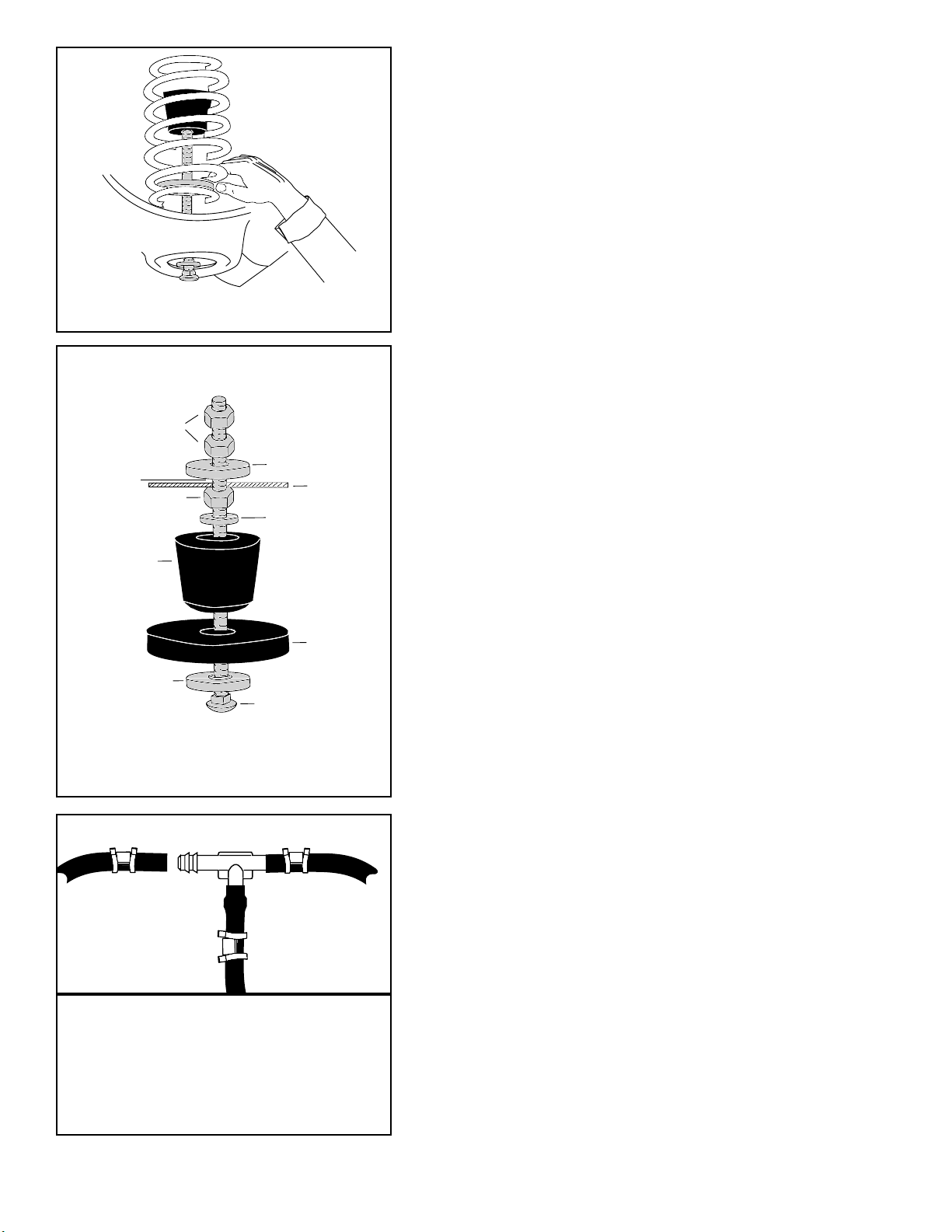
10. Guide the assembly through upper shock bolt hole
and attach with large washer (with 3/8” hole) and
3/8” nut. Hand tighten only at this time (Figure 3).
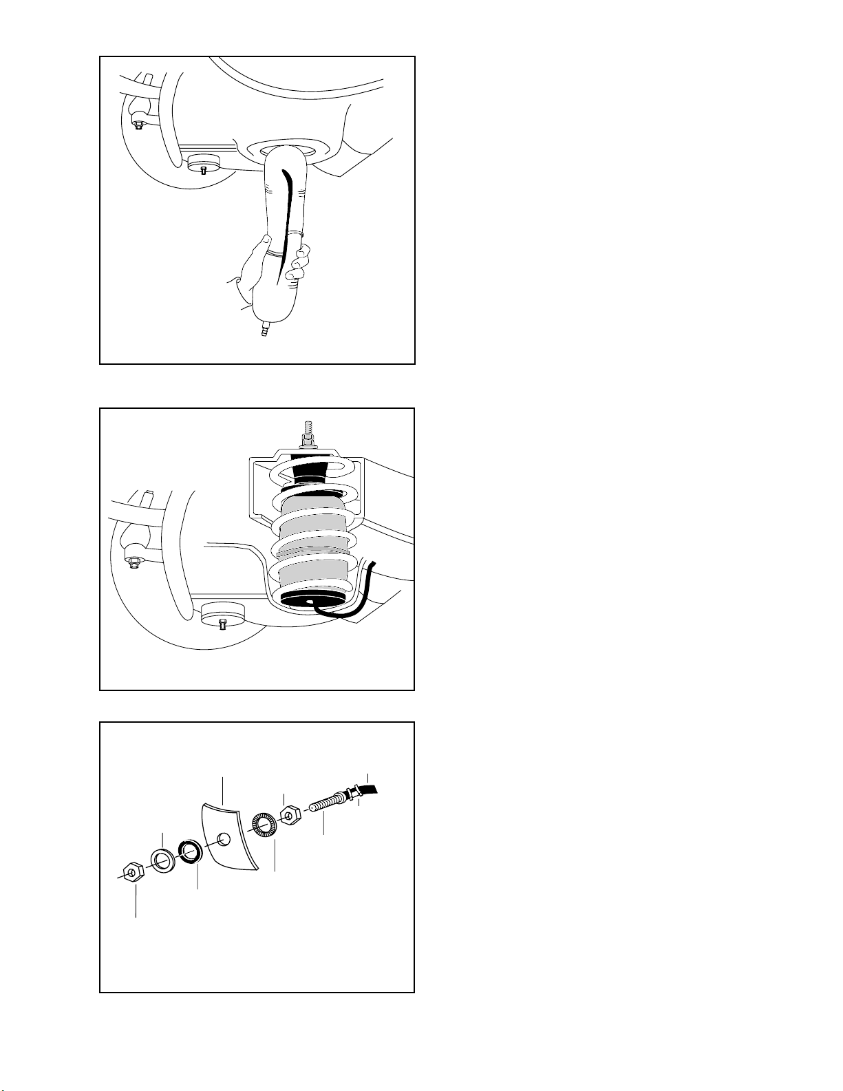
11. Remove black cap and squeeze air out of cylinder
and fold into a hot dog bun shape. Put black cap on
to retain deflated shape. Insert into lower spring
seat hole with stem down and push all the way into
spring (Figure 4). Slide thin spacer into spring at
bottom of cylinder and pull cap off so cylinder will
obtain its as molded shape.
12. Install air line clamp onto air line and install air line
onto the barbed stem of cylinder. With pliers slide
the air line clamp until it fully covers barbed section
of stem (Figure 3A).
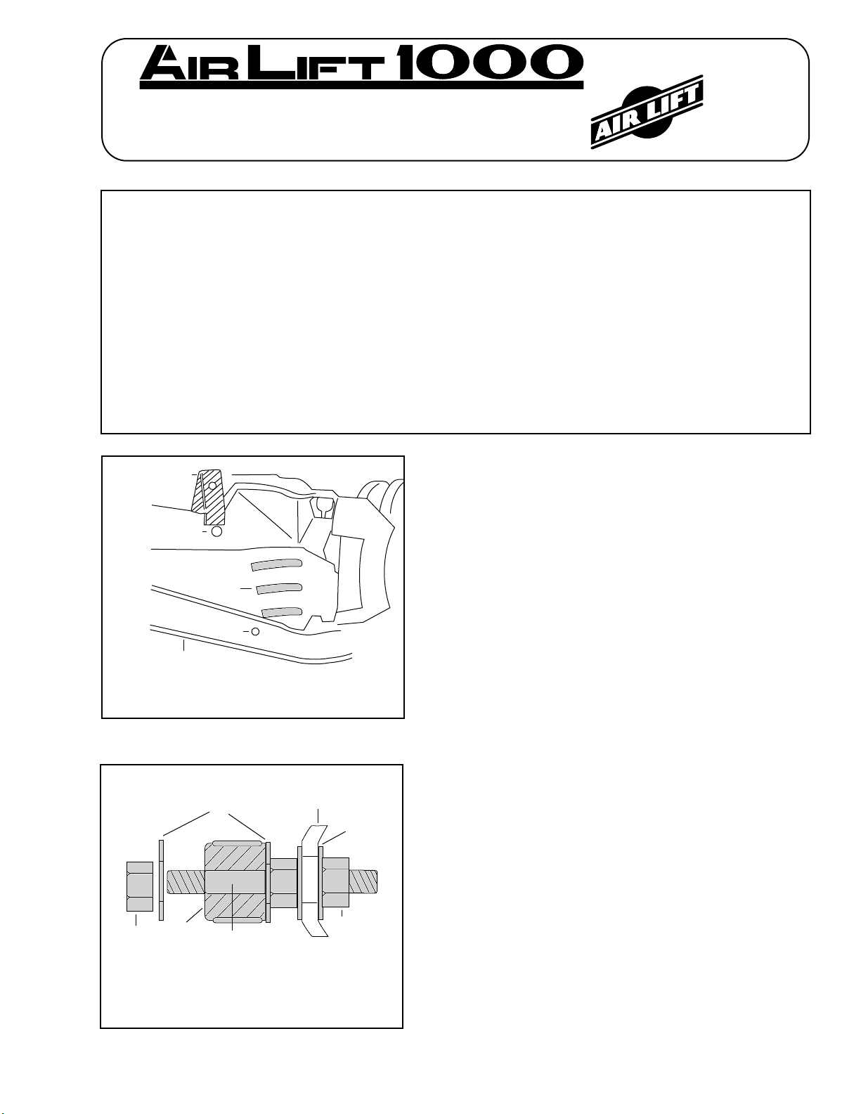
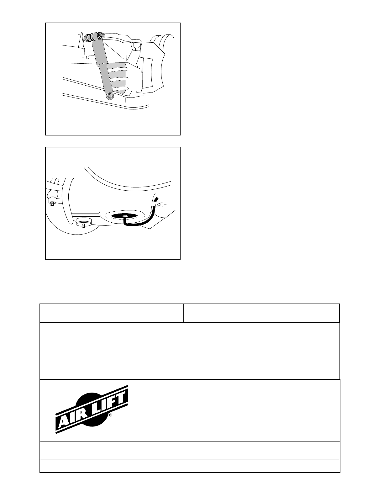
13. With air line installed on the cylinder, route airline
forward on inside of A-Arm. There are hose clips
and bolts supplied in the kit to attach air line to the
lower A-Arm. Locate and drill 3/8” hole. Attach the
clip to theA-Arm using the 3/8-16X1” bolts and nuts
supplied in kit (Figure 8). If air line is routed near a
high heat source (headers, manifold, etc.) use the
thermal sleeves supplied in effected areas.
Tee air line installation recommended unless weight in
vehicle varies from one side to the other and unequal
pressures are needed to level the load. Dual air lines are
used in this case.
TEE AIR LINE ROUTING
TO PREVENT AIR LINE FROM MELTING, KEEP IT AT
LEAST EIGHT INCHES FROM EXHAUST SYSTEM.
A. Locate desired tee location on the frame rail or
cross member.
B. Route along cross member from the lower spring
seat to tee location. Attach with plastic straps or
wire.
CAUTION: LEAVE SUFFICIENT AIR LINE SLACK TO
PREVENT ANY STRAIN ON FITTING DURING AXLE
MOTIONS.
C. Cut off excess air line and slide air line clamp onto
the air line. Push the air line over one side of the tee
until all the barbs are covered. Repeat procedure
for other leg of tee.
D. With pliers slide the air line clamp forward until it
fully covers the barbed section. Repeat for the air
line from the other air cylinder (Figure 3A).
E. Select a location for the inflation valve assuring that
the valve will be protected and accessible with an air
hose.
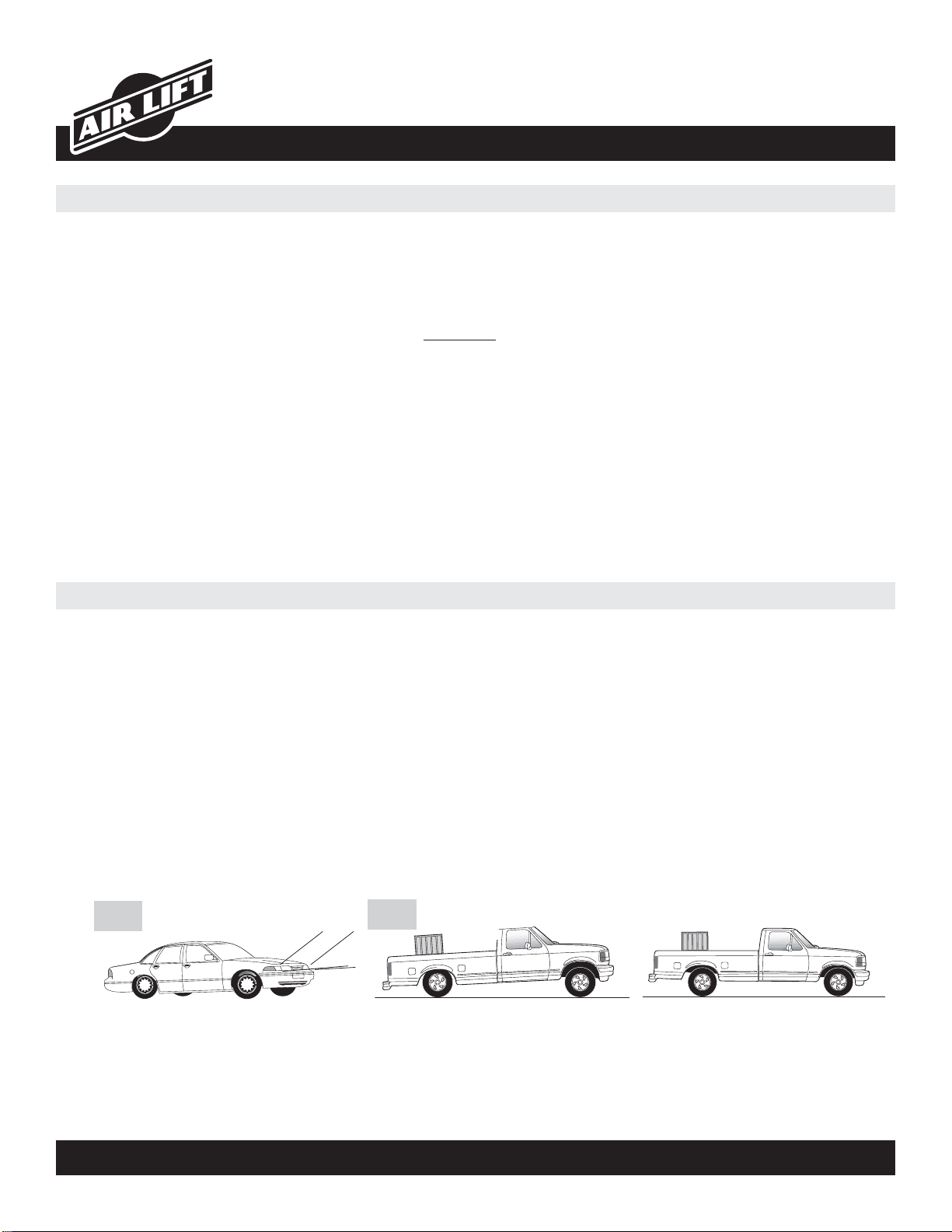
Figure 2