BilJax ESP 19 User manual


2
This equipment is designed and manufactured in
compliance with the duties, responsibilities and
standards set forth in the ANSI, CE, CSA and/or AS
standards in effect at the time of manufacture.
This equipment will meet or exceed applicable ANSI,
CE, CSA and/or AS codes and standards when
operated in accordance with manufacturer’s
recommendations.
It is the responsibility of the user to follow all
regional codes and regulations that govern the safe
operation of this equipment.
Obtain, read and obey all safety precautions before
performing maintenance or repairs or attempting to
operate this equipment. This includes all manufacturer
recommendations as well as those directives set forth by
government and local authorities.
To ensure proper and safe use of this equipment, it is
strongly recommended that only trained and authorized
personnel attempt to operate and maintain the boom lift.
This manual shall be considered a permanent and
necessary component of the machine and shall be
kept with the boom lift at all times.
Owners and Lessors should complete a full inspection of
all components and perform a test of all functions,
including brake functions, before commissioning or
reselling the machine. Repair or replace all damaged or
malfunctioning components.
Bil-Jax, Inc. is dedicated to the continuous improvement
of this and all Bil-Jax products. Therefore, equipment
information is subject to change without notice. Direct
any questions or concerns regarding errors or
discrepancies in this manual to the Bil-Jax Service
Department.
Copyright © Bil-Jax, Inc. 2008. All Rights Reserved.
“Bil-Jax” is a registered trademark and “A Step
Above” and “X-Boom” are trademarks of Bil-Jax,
Inc. Contact Bil-Jax for replacement manuals.
125 Taylor Parkway
Archbold, Ohio 43502
Phone (800) 537-0540
(419) 445-8915
Fax (419) 445-0367
B33-01-0110

3
TABLE OF CONTENTS
TABLE OF CONTENTS 3
ILLUSTRATIONS AND TABLES 4
1 SAFETY 5
LEGEND: SAFETY ADVISORIES 6
BEFORE OPERATION 7
DURING OPERATION 7
MAINTENANCE SAFETY 9
BATTERY MAINTENANCE 9
DAMAGED EQUIPMENT POLICY 10
2 INTRODUCTION 11
SPECIFICATIONS 12
WARRANTY 12
3 OPERATION 13
OPERATOR CONTROLS 13
NORMAL OPERATING PROCEDURE 15
EMERGENCY LOWERING PROCEDURE 16
LIFT VEHICLE TRANSPORT 17
4 MAINTENANCE 19
SCHEDULED SERVICE CHECKS 19
UNDERGUARD SERVICE CHECK 21
HYDRAULIC SYSTEM 23
PRESSURE RELIEF VALVE ADJUSTMENT 24
FLOW RESTRICTOR VALVE REPLACEMENT 24
VALVE OPERATION 25
HYDRAULIC CYLINDER REPAIR 26
ELECTRICAL SYSTEM 27
LIFT CHAINS AND SLIDE BLOCKS 28
TROUBLESHOOTING 30
TROUBLESHOOTING AIDS 33
DECAL REPLACEMENT 47
APPENDIX A: PART LISTS 51
APPENDIX B: REFURBISHMENT 81

4
TABLES AND ILLUSTRATIONS
Table 1-1 Minimum Safe Approach Distances 7
Table 2-1 Specifications 12
Figure 3-1 Lower Control Box 13
Figure 3-2 Upper Control Box 14
Figure 3-3 Battery On/Off Switch 15
Figure 3-4 Emergency Lowering Valve 16
Figure 3-5 Lifting and Tow Procedures 17
Figure 3-6 Travel Brake and Steering Linkage 17
Table 4-1 Daily/Weekly Service Checks 19
Table 4-2 6 Month/Yearly Service Checks 20
Figure 4-1 Underguard 21
Figure 4-2 Lift Chains Lubrication 22
Figure 4-3 Mast Slide Ways Lubrication 22
Figure 4-4 Rear Casters Lubrication 22
Figure 4-5 Front Caster Pillow Block Lubrication 22
Figure 4-6 Pressure Relief Valve Adjustment 24
Figure 4-7 Flow Restrictor Valve 24
Figure 4-8 Valve Operation 25
Figure 4-9 Hydraulic Cylinder Disassembly 26
Figure 4-10 Battery Charger Cord 27
Figure 4-11 Chain Elongation Inspection 28
Figure 4-12 Lift Chains Adjustment 28
Figure 4-13 Slide Blocks Adjustment 29
Table 4-3 Troubleshooting 30
Figure 4-14 Main Controller Board 33
Table 4-4 Main Controller LED Indicators 34
Figure 4-15 Hydraulic Diagram 40
Figure 4-16 PC Logic Diagram 41
Figure 4-17 Electrical Layout 42
Figure 4-18 Drive Wiring Diagrams 43
Figure 4-19 Upper Control Wiring Diagram 45
Table 5-1 Replacement Decals 48
Figure 5-1 Decal Locations, Side View 49
Figure 5-2 Decal Locations, Rear View 50

5
1SAFETY
Proper training is required for the safe operation of any mechanical device.
Failure to follow all instructions and safety precautions in this manual and
attached to the lift will result in death or personal injury.
Prior to Operation:
Read, understand and obey all instructions and safety precautions in this
manual and attached to the lift.
Read, understand and obey all applicable government regulations.
Become familiar with the proper use of all controls.
Inexperienced users should receive instruction before attempting to
operate or maintain the machine.
The use of intelligence and common sense is the best practice when following
any safety policy.

6
LEGEND: SAFETY ADVISORIES
The following safety advisories are used throughout
this manual to indicate specific hazards when
operating or maintaining the machine. Read,
understand and obey all safety advisories to prevent
improper service, damage to equipment, personal
injury or death.
DANGER
Warns of operation near electrical power
sources that could lead to personal injury or
death.
WARNING
Describes conditions or practices that could lead
to personal injury or death.
CAUTION
Contains information important in the prevention
of errors that could damage machine or
components.
NOTE: Contains additional information
important for performing a procedure.

7
BEFORE OPERATION DURING OPERATION
Read and observe the following general safety
precautions before operating the ESP 19.
ALWAYS survey the usage area for potential
hazards such as untampered earth fills, unlevel
surfaces, overhead obstructions, and electrically
charged conductors or wires. Be aware of any
potential hazards and always consider what could
happen. Watch for moving vehicles in the operating
area.
ALWAYS read, understand, and follow the
procedures in this manual before attempting to
operate equipment.
ALWAYS inspect the equipment for damaged or
worn parts. Check for cracked welds, hydraulic
leaks, damaged wiring, loose wire connectors,
damaged casters, and damaged pothole guards.
Also check for any improper operation. NEVER
operate equipment if damaged in any way.
Improperly operating equipment must be repaired
before using.
ALWAYS wear proper clothing for the job. Wear
protective equipment as required by federal, state,
or local regulations.
ALWAYS locate, read, and follow all directions and
warnings displayed on the equipment.
ALWAYS inspect the equipment for “DO NOT USE”
tags installed by maintenance personnel. NEVER
use tagged equipment until repairs are made and all
tags are removed by authorized maintenance
personnel.
ALWAYS make sure the platform is free of mud,
grease, or other foreign material. This will reduce the
possibility of slipping.
NEVER allow improperly trained personnel to
operate this equipment. Only trained and authorized
personnel shall be allowed to operate this
equipment.
NEVER operate this equipment if you are under the
influence of alcohol or drugs or if you feel ill, dizzy,
or unsteady in any way. Operators must be
physically fit, thoroughly trained, and not easily
excitable.
NEVER modify, alter, or change the equipment in
any way that would affect its original design or
operation in any way.
NEVER operate this equipment in ways for which it
is not intended.
Ensure the following general safety precautions are
followed while operating the ESP 19:
DANGER
This machine is NOT insulated for use near
electrical power lines and DOES NOT provide
protection from contact with or close proximity
to any electrically charged conductor. Operator
must maintain safe clearances at all times (3.05
meters minimum) and must always allow for
platform movement due to gusty winds. Always
contact power company before working near
power lines. Assume every power line is live.
Power lines can be blown by the wind. Refer to
Table 1-1 for minimum safe approach distances
between the machine and electrical power lines.
Table 1-1. Minimum Safe Approach Distances
ALWAYS position lift far enough away from power
sources to ensure that no part of the lift can
accidentally reach into an unsafe area.
ALWAYS operate only on a firm and level surface.
NEVER use on surfaces that do not support the
weight of the equipment and its rated load capacity.
ALWAYS keep yourself and all personnel away from
potential pinch or shear points.
ALWAYS report any misuse of equipment to the
proper authorities. Horseplay is prohibited.
ALWAYS maintain good footing on the platform.
NEVER wear slippery soled shoes.
ALWAYS make certain all personnel are clear and
there are no obstructions before repositioning
platform.
Minimum Safe Approach Distance
Voltage Range
(Phase to Phase) (Feet) (Meters)
0 to 300V Avoid Contact
Over 300V to 50KV 10 3.05
Over 50KV to 200KV 15 4.60
Over 200KV to 350KV 20 6.10
Over 350KV to 500KV 25 7.62
Over 500KV to 750KV 35 10.67
Over 750KV to 1000KV 45 13.72

8
ALWAYS cordon off area around the base to keep
personnel and other equipment away from it while in
use.
ALWAYS stay clear of wires, cables, and other
overhead obstructions.
ALWAYS disconnect power at the batteries when
not in use to guard against unauthorized use.
NEVER allow electrode contact with any part of the
platform if welding is being performed from the
platform.
NEVER override or by-pass manufacturer's safety
devices.
NEVER release the travel brake or tow the lift
vehicle while a person or materials are on board.
NEVER stand or sit on guard rails. Work only within
the platform guard rail area and do not lean out over
guard rails to perform work.
NEVER attempt to increase working height with
boxes, ladders, or other means.
NEVER operate this equipment when exposed to
high winds, thunderstorms, ice, or any other weather
conditions that would compromise the safety of the
operator.
NEVER climb up or down masts.
NEVER allow ropes, electric cords, hoses, etc. to
become entangled in the equipment when the
platform is being raised or lowered.
NEVER exceed manufacturer's platform load limits
and make sure all materials are evenly distributed
over the entire platform.
NEVER exceed platform load ratings by transferring
loads to platform at elevated heights.
NEVER use guard rails to carry materials and never
allow overhang of materials when raising or lowering
platform.

9
MAINTENANCE SAFETY
Read and observe the following general safety
precautions when performing maintenance on the
ESP 19.
ALWAYS perform maintenance procedures
according to manufacturer's requirements. NEVER
short change maintenance procedures.
ALWAYS check hydraulic system. Make sure all
lines, connectors, and fittings are tight and in good
condition.
ALWAYS keep all mechanisms properly adjusted
and lubricated according to maintenance schedule
and manufacturers specifications.
ALWAYS perform a function check of operating
controls before each use and after repairs have
been made.
ALWAYS locate and protect against possible pinch
points prior to performing maintenance and repairs.
ALWAYS use only factory-approved parts to repair
or maintain this equipment. If this equipment is
rebuilt, retesting is required in accordance with
factory instructions.
NEVER add unauthorized fluids to the hydraulic
system or battery. Check manufacturers
specifications.
NEVER exceed the manufacturer's recommended
relief valve settings.
NEVER attempt repairs you do not understand.
Consult manufacturer if you have any questions
regarding proper maintenance, specifications, or
repair.
Battery Maintenance
Read and observe the following general safety
precautions when performing battery maintenance
on the ESP 19.
Check battery charge indicator for proper state of
charge on maintenance free batteries before using
lift.
ALWAYS wear safety glasses when working near
battery.
ALWAYS avoid contact with battery acid. Battery
acid causes serious burns. Avoid contact with skin or
eyes. If accidental contact occurs, flush with water
and consult a physician immediately.
ALWAYS disconnect ground cable first when
removing battery.
ALWAYS connect ground cable last when installing
battery.
ALWAYS charge batteries in open, well-ventilated
areas.
NEVER smoke when servicing battery.
NEVER allow batteries to overcharge and boil.
NEVER short across battery posts to check for
current. NEVER break a live circuit at battery.
NEVER jump start other vehicles using lift battery.

10
DAMAGED EQUIPMENT POLICY
Safety Statement
At Bil-Jax, we are dedicated to the safety of all users of our products. Therefore,
all Bil-Jax lifts are designed, manufactured, and tested to comply with current
applicable Federal OSHA and ANSI codes and regulations.
Damage Policy
There may be occasions when a Bil-Jax lift is involved in an incident that results
in structural damage to the lift. This can seriously compromise the ability of the lift
to perform in a safe manner. Therefore, whenever a Bil-Jax lift is damaged
structurally or when there is the possibility of structural damage (this damage
may be internal and is not always visible to the naked eye), Bil-Jax requires that
the lift be returned to our facility at 125 Taylor Parkway, Archbold, Ohio, for
reconditioning. If you have any questions concerning what constitutes structural
damage, please call the Bil-Jax Service Department at 800-537-0540.
Damage Repair Notice
There may be occasions when a Bil-Jax lift is involved in an incident resulting in non-
structural damage. When this occurs and repairs are made by the owner or area
distributor, please notify Bil-Jax of these non-maintenance repairs and request a repair
form to be filled out and returned to Bil-Jax.

11
2INTRODUCTION
The ESP 19 hydraulic lift is designed and manufactured for use as a warehouse
stocking and order picking vehicle. Its guard rail design permits the operator to
ride on the platform with the load, while transferring parts to and from multiple
overhead storage locations. The maximum platform load is limited to 450 lbs.
All ESP 19 operations are powered by a 24-Volt DC battery package. A 40-amp
battery charger and plug-in receptacle are included in the system for recharging
the batteries at the end of each work period. A charge level indicator displays the
battery charge status.
The platform lift function is hydraulic, including a hydraulic cylinder, reservoir, and
pump. The hydraulic pump motor is driven by a 24-Volt DC electric motor.
Elevation is by a 1-3/4 inch linear-displacement hydraulic cylinder and four
telescoping mast sections. The lower mast section is raised by hydraulic cylinder.
The upper mast sections are raised mechanically by connecting sets of chains
and sheaves (pulleys). The lift platform rises four inches for each inch of
hydraulic cylinder extension.
Other electrically powered functions include a two-wheel drive transaxle for floor
travel and pushbutton steering. The maximum travel speed is enabled only when
the lift platform is down. When the platform is raised, the travel speed is limited.
The transaxle includes an electric brake that locks the drive wheels whenever
forward or reverse travel is halted. The electric brake is normally applied; the
brake disengages when forward or reverse travel is enabled with the joystick. In
case of a loss of battery power, a manual free wheel lever can be used to
disengage the electric brake, allowing the lift vehicle to be towed.
Floor travel and platform lift functions are controlled from an upper control box
located on the lift platform. Floor travel is by joystick control with pushbutton
steering. Lift functions are by pushbutton control. Platform lift can also be
controlled from a lower control box mounted on the vehicle base. An electronic
level sensor disables all lift and travel functions except platform lowering if the lift
vehicle base is more than one degree out of level. While out of level, travel can
be resumed after the lift platform is fully lowered.
With equipment power on or off, turning an emergency lowering valve knob
lowers the lift platform at a controlled, safe speed. The lowering valve knob is
visible and readily accessible from floor level.
Proper lift vehicle operation and safety are assured by performing the scheduled
inspection and maintenance procedures set forth in this manual. The risk of
platform free-fall is eliminated by proper maintenance of the chains, sheaves and
sheave pins, a properly installed flow restrictor valve, and a clean mast. The
restrictor valve (non-adjustable) fixes the maximum rate of platform descent to
approximately 0.6 feet per second, whether the platform is empty or fully loaded.
With the restrictor valve properly installed, a hydraulic hose failure will result in
the same maximum rate of descent.
Carefully read and understand all of the safety instructions in Section 1 and
all operating instructions in Section 3 of this manual before operating the lift
vehicle

12
SPECIFICATIONS
ESP 19 Electric Hydraulic Lift Platform
Model Number ESP 19 Serial Number ________________
Manufactured by: Bil-Jax, Inc.
125 Taylor Parkway
Archbold, Ohio 43502
800-537-0540
Table 2-1. Specifications
Rated Platform Load 450 lbs (204 kg) total including operator
[1 person + materials not to exceed 450 lbs (204 kg)]
Extended Platform Height 19 ft 3 in (5.9 m)
Retracted Platform Height 20 in. (50.8 cm)
Platform Dimensions 30 in. W x 30 in. L x 42 in. H
(0.76 m x 0.76 m x 1.07 m)
Base Dimensions 30-1/2 in. W x 63 in. L x 80 in. H
(0.77 m x 1.60 m x 2.03 m)
Gross Shipping Weight 2150 lbs (975 kg)
Platform Lift Time 20 seconds empty, 32 seconds loaded
Platform Retraction Time 22 seconds empty, 22 seconds loaded
Platform Lift Rate Lift platform empty: 0.66 ft (0.3 m)/sec.
Lift platform loaded: 0.42 ft (0.19 m)/sec.
Hydraulic System Pressure 1200 psi empty, 2100 psi loaded
Travel Speeds (Maximum) Lift platform lowered: 2.5 mph
Lift platform raised: 0.5 mph
Power Source DC – two in-series 12 volt maintenance-free batteries
WARRANTY
Bil-Jax warrants its telescopic lifts for one year from the date of delivery against
all defects of material and workmanship, provided the unit is operated and
maintained in compliance with Bil-Jax’s operating and maintenance instructions;
structural components are warranted for three years. Bil-Jax will, at its option,
repair or replace any unit or component part which fails to function properly in
normal use.
This warranty does not apply if the lift and/or its component parts have
been altered, changed, or repaired without the consent of Bil-Jax or by anyone
other than Bil-Jax or its factory trained personnel, nor if the lift and/or its
components have been subjected to misuse, negligence, accident or any
conditions deemed other than those considered as occurring during normal use.
Components not manufactured by Bil-Jax are covered by their respective
manufacturer’s warranties. A list of those components and their warranties is
available upon written request to Bil-Jax.
Bil-Jax shall not in any event be liable for the cost of any special, indirect,
or consequential damages to anyone, product, or thing. This warranty is in lieu of
all other warranties expressed or implied. We neither assume nor authorize any
representative, or other person, to assume for us any other liability in connection
with the sale, rental, or use of this product.

13
3OPERATION
OPERATOR CONTROLS
Most of the operator controls for the ESP 19 are located on the upper and lower
control boxes. Other operator controls include the BATTERY ON/OFF switch and
the emergency lowering valve. The BATTERY ON/OFF switch, located on the left
side of the lift base, is the main power disconnect switch for the lift vehicle. The
location and operation of the emergency lowering valve is described in paragraph
3-3.
Lower Control Box
The lower control box, Figure 3-1, is located on the lift base and contains three
controls: UP/DOWN, EMERGENCY STOP, and UPPER CONTROL/OFF/LOWER
CONTROL. The lower control box enables lift operations from floor level.
The UPPER CONTROL/OFF/LOWER CONTROL key switch selects the active
(upper or lower) control location. To enable an UP or DOWN lift motion from the
floor, turn and hold the key switch in the LOWER CONTROL position. To enable
lift vehicle travel or platform elevation from the upper control box, turn the key
switch to the UPPER CONTROL position. To disable lift vehicle operations, turn
the key switch to the OFF position and remove the key.
Turn the UP/DOWN selector switch to the UP position to raise the lift platform or
to the DOWN position to lower the platform. (The key switch must be held in the
LOWER CONTROL position to enable the UP/DOWN selector switch).
Press the EMERGENCY STOP button to stop all equipment motion. If the lift
vehicle is moving forward or back, pressing the EMERGENCY STOP button
engages the travel brake causing travel to stop quickly. To resume lift vehicle
operation, turn the EMERGENCY STOP button clockwise.
Figure 3-1. Lower Control Box
14
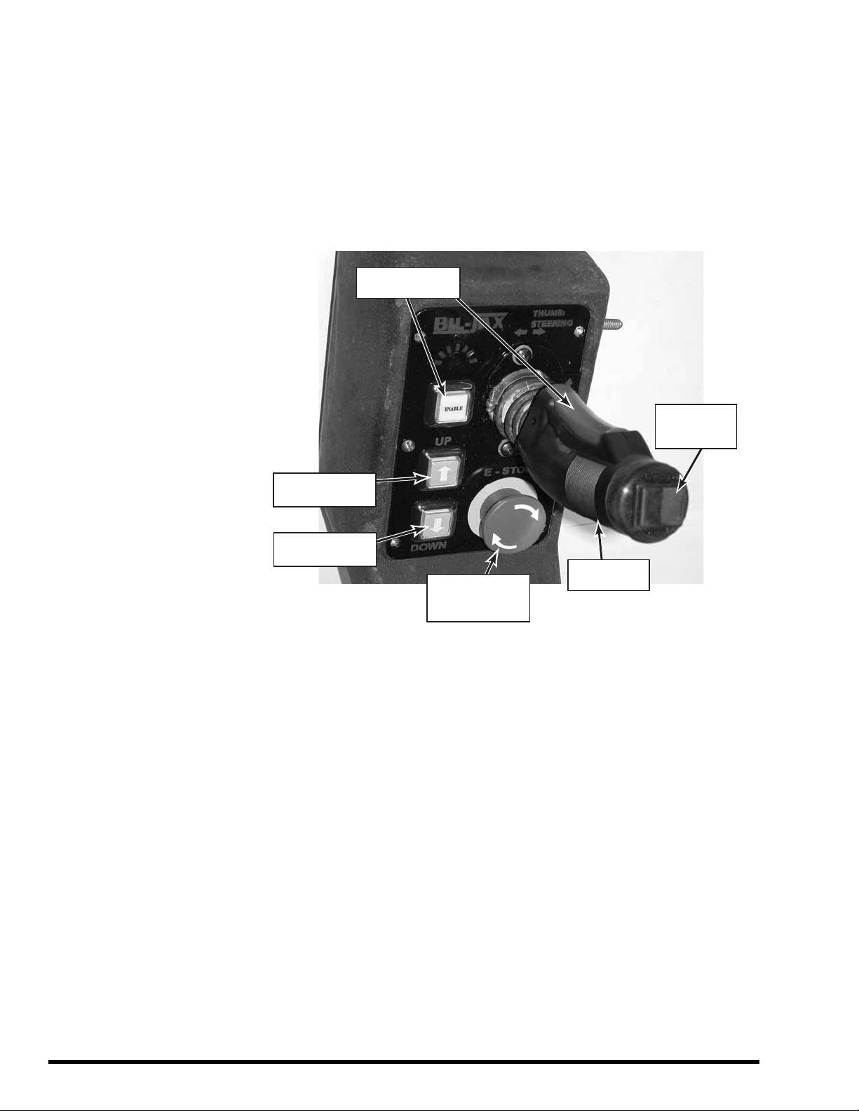
Upper Control Box
The upper control box, Figure 3-2, is in the lift cage. The upper control box
enables lift and travel operations whenever the BATTERY ON/OFF switch is in
the ON position and the lower control box key switch is in the UPPER CONTROL
position.
Upper control box controls include four pushbuttons and a forward/reverse floor-
travel joystick with thumb-switch steering.
TRAVEL
JOYSTICK
STEERING
THUMB
SWITCH
ENABLE
PUSHBUTTONS
EMERGENCY
STOP
PUSHBUTTON
UP
PUSHBUTTON
DOWN
PUSHBUTTON
Figure 3-2. Upper Control Box
Press and hold either one of the ENABLE pushbuttons to enable a control
function. An ENABLE pushbutton must be pressed to enable the lift, steering,
and travel functions. The ENABLE pushbutton must be held down to continue the
equipment function.
With one of the ENABLE pushbuttons depressed, press the UP [] pushbutton
to raise the platform or press the DOWN [] pushbutton to lower the platform.
With one of the ENABLE pushbuttons depressed, move the travel joystick
forward or back to move the lift vehicle in the forward or reverse direction. For
slow speeds, move the joystick forward or back just a little. For faster speeds,
move the joystick more.
With one of the ENABLE pushbuttons depressed, press the left or right side of
the thumb switch to steer the rear wheels to the left or right. The steering can be
adjusted before or during floor travel.
Press the EMERGENCY STOP button to stop all equipment motion. If the lift
vehicle is moving forward or back, a travel brake is applied causing travel to stop.
To resume lift vehicle operations, turn EMERGENCY STOP button clockwise.

15
NORMAL OPERATING PROCEDURE
Perform the following procedures to operate the
ESP 19 platform lift vehicle.
Read and follow all safety precautions contained in
Section 1 and all responsibilities outlined in the ANSI
A92.3 reprint in Section 7 of this manual.
Check the lift vehicle for damage or worn parts. If
damage or part wear is found, do not operate the
vehicle until the problem is corrected.
Make sure battery charger cord is disconnected from
wall outlet. Place cord back into its box and close
and latch lid. LIFT WILL NOT OPERATE IF LID IS
NOT CLOSED SECURELY.
Turn the BATTERY ON/OFF switch, Figure 3-3, to
the ON position.
Observe the battery charge level indicator. Verify
that the battery charge level is 3/4 or more.
Figure 3-3. Battery On/Off Switch
Turn the UPPER CONTROL/OFF/LOWER
CONTROL key switch, Figure 3-1, to the UPPER
CONTROL position.
Enter the platform cage and close the entry gate.
LIFT WILL NOT OPERATE IF THE GATE IS NOT
CLOSED COMPLETELY.
Use the upper control box controls to operate the lift
vehicle.
Position the lift vehicle at the work area. Make sure
the vehicle is on a firm and level surface and that
there are no potential hazards such as speed
bumps, open floor drains, potholes, overhead
obstructions or electrically charged conductors. Do
not operate the lift vehicle if such hazards exist in
the immediate area.
NOTE: The lift vehicle is equipped with a level
sensor. When the vehicle is on a slope greater
than 1 degree, the level sensor disables all
functions other than platform lowering and
sounds an alarm beeper. Once the platform is
lowered, floor travel is again enabled to allow
travel to a level area.
During floor travel and lift operations, the alarm
beeper should sound. If the alarm beeper does not
work properly, do not operate the lift vehicle.
During lift platform descent, the amber caution light
should blink on and off. If the caution light does not
blink on and off, do not use the lift vehicle.
If any equipment motion continues after the
pushbutton, joystick, or selector switch is released,
press the EMERGENCY STOP pushbutton, Figure 3-2.
All equipment motion should stop immediately.
At the end of each workday and whenever a low
battery alarm sounds, transport the lift vehicle to the
recharge site and plug in the charge cord. Verify that
the ON-CHARGING indicator lights up on the battery
charger.
NOTE: For more information on battery charging
operations, refer to the battery charging
procedure in paragraph 4-4.
To shut down the equipment, turn the UPPER
CONTROL/OFF/LOWER CONTROL key switch and
the BATTERY ON/OFF switch to OFF. Remove the
key to prevent unauthorized equipment operation.

16
EMERGENCY LOWERING PROCEDURE
In an emergency, a person at floor level can lower
the platform by holding the UPPER
CONTROL/OFF/LOWER CONTROL key switch in
the LOWER CONTROL position and turning the
UP/DOWN selector switch to the DOWN position. (If
the upper control box emergency stop pushbutton is
depressed, the platform will not lower.)
An emergency lowering valve is shown in Figure 3-4.
In case of a total loss of battery power, a person at
floor level can safely lower the platform by opening
the emergency lowering valve.
WARNING
Do not climb out of the lift cage while the lift
platform is elevated. The lift mast cannot be
climbed safely. An elevated lift platform has a
high center of gravity and can be tipped easily.
Standing on or leaning out from the outside of
a cage rail may cause the lift vehicle to tip over.
Tipping the lift vehicle over can cause severe
injury or death and equipment damage.
If you lose power while elevated in the cage, instruct
someone on ground level to open the emergency
lowering valve. Do not leave the cage to climb down
the lift mast or storage shelves.
To lower the platform, pull and hold the red valve
knob until the platform starts to descend. When the
platform is fully lowered, release the knob to close
the valve.
Figure 3-4. Emergency Lowering Valve

17
LIFT VEHICLE TRANSPORT
The platform vehicle is equipped with lifting and tow
features, Figure 3-5. Read the following instructions before
using these features to lift or tow the vehicle.
Figure 3-5. Lifting and Tow Features.
CAUTION
Do not attempt to push the lift vehicle or use
the lift vehicle to pull another vehicle or object.
Pushing the lift vehicle or using the vehicle for
towing may cause serious equipment damage.
The forks of a lift truck (2-ton minimum capacity) can
be used to raise the ESP 19 for loading onto a trailer
or for blocking up the lift vehicle for maintenance.
Forks must be inserted a minimum of 32 inches
before raising the ESP 19.
Before towing the ESP 19 lift vehicle, you must
manually disengage the travel brake and disconnect
the steering cylinder from the steering linkage. Refer
to the illustrations in Figure 3-6.
Figure 3-6. Travel Brake and Steering Linkage

18

19
4MAINTENANCE
SCHEDULED SERVICE CHECKS
Daily/Weekly Service Checks
Perform the daily and weekly service checks listed in Table 4-1.
Table 4-1. Daily/Weekly Service Checks
Service Check Daily
before use Weekly
Check that all upper and lower control box controls
work properly.
Check for hydraulic oil leaks.
Check for loose or missing parts.
Check for and retighten loose nuts and bolts.
Check that cage gate is secure.
Ensure Operation Manual is in manual tube.
Verify that underguard shuts down operation when
weight is applied.

20
6 Month/Yearly Service Checks
Perform the service checks in Table 4-2 every 6 months or every 12 months, as
indicated.
Table 4-2. 6 Month/Yearly Service Checks
Service Check Every
6 months Every
12 months
Check chain assemblies for split
leaves, loose pins, excessive
wear, or elongation.
Verify that cage is securely bolted
to lift mast.
Check that slide blocks and their
paths are clean and lightly
lubricated with a dry silicone
lubricant.
Verify that all safety decals are
present and legible.
Check for wear on chain
sheaves, sheave axles, and
bearings.
Check caster axle and swivel
bolts for wear.
Check casters for cracks or
excessive wear.
Lubricate lift chains with 40-
weight oil.
Check hydraulic UP and DOWN
valves operation.
Clean battery terminals.
Check operation of emergency
lowering valve.
Grease rear caster swivel bolts,
axles and wheels.
Grease steering linkage pivot
bolts.
Grease front caster pillow blocks.
Check battery cables and wiring
for loose connections and
damaged wires.
Replace hydraulic oil.
Check slide blocks for wear.
Check for mast sway.
Load test with 450 pounds.
Table of contents
Other BilJax Lifting System manuals


Popular Lifting System manuals by other brands


Mortuary Lift
Mortuary Lift ULTIMATE 1000 instructions

Reechcraft
Reechcraft PowerLift PL50 Operators safety manual

Oshkosh Corporation
Oshkosh Corporation JLG AE1932 Service maintenance manual

Genie
Genie S-60 HC Service manual

Powermate
Powermate LiftGate LV-TL Series Installation & operation manual

stertil-KONI
stertil-KONI ST 1065-FWF Service and parts manual