PNI PNI-ZM101-EV User manual

1
User Manual
PNI-ZM101-EV
ZigBee
TM
-ready
Wireless Network Evaluation Board
Using the UZ2400 RF chip
And the 78K0R/KE3 Microcontroller

2
1 SAMPLE APPLICATION
Two sample applications are included in this evaluation kit.
•RF test program
•MAC library sample program: send and receive message.
A IEEE 802.15.4 compliant MAC library is included in this evaluation kit. It
is a linkable object-code library. “C” source code is provided for both RF
test program and MAC library application program.
The ZM101-RS boards are pre-programmed with RF test program. All
sample programs provide console program through the RS232 interface. A
terminal program such as Hyperterminal is required to interact with the
sample program and a NULL MODEM cable is needed to connect PC’s
COM port to evaluation kit’s RS232 DB9 connector.
In case no COM port is available from your PC, you can set the USB
interface to COM port mode. Please refer to Section 3.2.4 how to setup
jumper J1, J2, J3 for the USB COM port mode. When USB interface to set
to USB COM port mode, the On-Chip Debug function is disable, because it
is the same UART interface for the debug and COM port. To indentify USB
COM port number, you can find it from [Control Panel] -> [System] ->
[Hardware] -> [Device Manager] -> [Ports (COM *LTP]. Following is the
table to setup Hyperterminal to connect to sample program’s console.

3
Table 1 Hyperterminal port configuration.
Baud rate
19200
Data bits
8
Parity
None
Stop bits
1
Flow control
None
Local echo
Off
Line feed
No
1.1 RF test sample application
Two PNI-ZM101-EV boards are required to conduct this test. J5 to J8 is
used to setup the board 4 LSB address. Set one unit’s address to 0x0001 and
the other unit’s address to 0x0002. Connect PNI-ZM101-EV to PC’s USB

4
port or COM port, you shall be the following screen. If not, please push the
reset button.
1.1.1 Packet Error Rate (PER) Test
To start the PER test, first start the receiver board, the board with short
address “0002”, press 2 to initiate the receiver loop back function and in the
menu of the transmitter board, the board with short address “0001”, press 1
to setup PER test. The first prompt ask you to input the destination short
address, you may input “0002”, then you will be asked number of packets to
send during this PER test. Next, you will be prompted to input the interval
between two packets in ms and you may input 1 or larger value. When the
PER test finish. You will see:
-The number of packets sent.

5
-The number of packets received.
-The calculated PER in %.
-The maximum and minimum RSSI values in this PER test
RSSI is received signal strength indication. For the detail of the RSSI value,
please refer UZ2400 RF chip’s datasheet.
1.1.2 Continuous TX / Pseudo Noise
The menu item “3” initiates the modulates RF transmission. The data carried
are pseudo random numbers.
1.1.3 Continuous RX / Pseudo Noise
The menu item “4” initiates the carrier RF transmission.
1.1.4 RX mode
The menu item “5” initiates the receiver mode.
1.1.5 IDLE mode
The menu item “6” sets the UZ2400 into the IDLE mode.
1.1.6 Sleep mode
The menu item “7” sets the UZ2400 into the Deep Sleep mode.
1.1.7 Standby mode
The menu item “8” sets the UZ2400 into the Standby mode.
1.1.8 RF Channel Setting

6
The menu item “9” set the RF channel. The default RF channel is set
channel 11. It is assigned to RF frequency at 2405MHz, You can change the
channel in 5MHz step to the maximum channel at 2480MHz (channel 26).
To do it, please press “9” in the command prompt. Then, choose the channel
by [+], [-], [A], [B], or [C].
1.1.9 Manually set UZ2400 Chip Register
The menu item “0” is to set the UZ2400 registers. The register number for
adjusting the output power is 203. After input the register number, the
prompt will ask you to input the register value to assign. The value 0x00 is
the default value that means 0dBm. For detail of output power register,
please refer to UZ2400’s datasheet.
1.1.10 Resetting RF
The menu item “A” allows you to reset the UZ2400 chip registers.
1.2 MAC Sample program – Text Messaging
The MAC sample program provides a simple application to build a star
network utilizing the IEEE 802.15.4 PHY/MAC standard. It offers
•Designation of a network coordinator in a star configuration.
•Txext messaging between a coordinator and an end device.
The sample application supports one coordinator and up to 4 end devices for
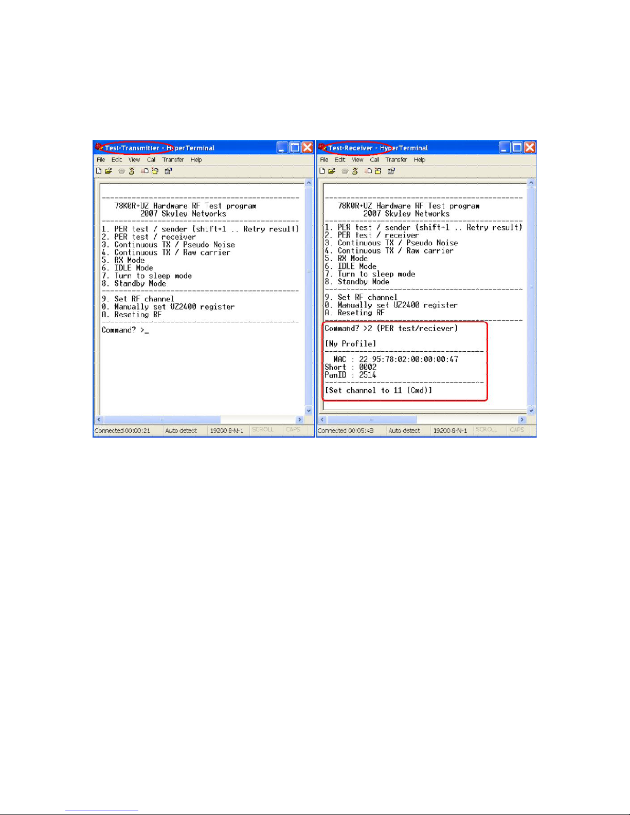
text messaging. Connect each PNI-ZM101-EV board to USB or COM port
of a PC and open HyperTerminal session for each PNI-ZM101-EV board.
To find the relevant USB COM port, check [Control Panel] -> [System] -> [Hardware]
-> [Device Manager] -> [Ports (COM & LPT)].

7
Now you shall find the following message in the hyperterminal, if not, reset
the evaluation board.

8
1.2.1 Designation of a coordinator
Now you choose a board to be a coordinator and in the hyperterminal which
is connect this board type “C” to enter coordinator mode. When successfully
started as a coordinator, the return status shall be 00. The coordinator is
ready to accept end device’s association.
1.2.2 Network Association
For all the other boards, they shall be the end device, please type “M” on the
hyperterminal that associated with each board to start the end device. When
successfully associated with the coordinator, the end device will be assigned
a short address by the coordinator and the return statur shall also be 00.
Do the same step for each board. The short address for each successive end
device shall increment by one when the association is successful. It then
ready to send the text message.
1.2.3 Text Messaging
To start sending the text message, press “S” in the HyperTerminal windows
and then a “Send to (short address)” will prompt you to enter an address. For
coordinator, type an end device address. For end device, type the
coordinator’s address. A “Message ?” will prompt you to type the text
message.
Table of contents
Other PNI Motherboard manuals