POK SA - ZI Les Guignons - 10400 Nogent-sur-Seine - FRANCE
Tel
:
03
25
39
84
78
-
Fax
:
03
25
39
84
90
-
Email
:
[email protected] -
Site
Web
:
www.pok.fr
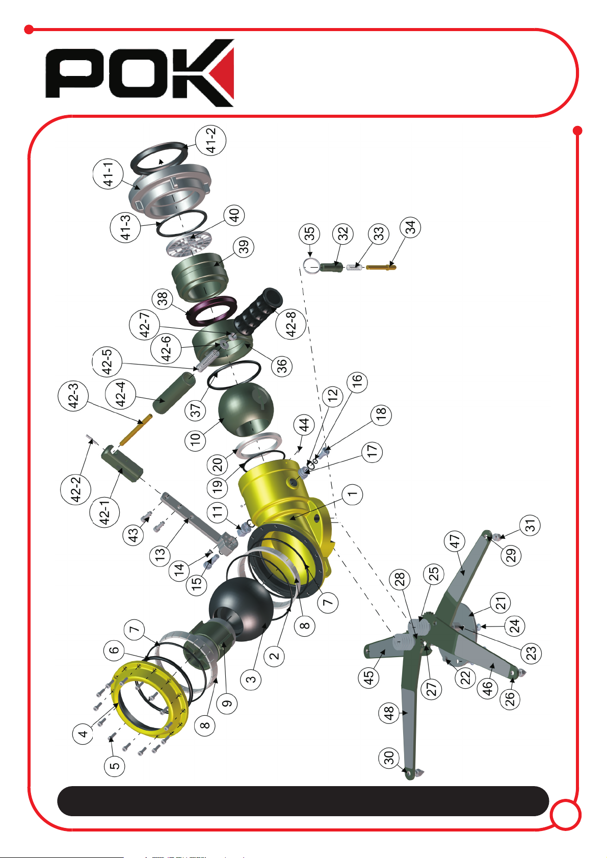
6Bill of materials
Doc 1741 EN
REP QTE DESIGNATION REF REP QTE DESIGNATION REF
1 1 Body 29605 31 4 Spike of stabilizating leg 17988
2 1 Gasket Ø158,34 x Ø3,53 32 1 Sheath of legs locking device 10901
3 1 Ball 29638 33 1 Spring of legs locking device 10900
4 1
Screwtop
29607 34 1 Piston of legs locking device 10899
5 14 Screw CHC M6-20 35 1 Double turn ring
6 1 Gasket R58 36 1 Gasket carrying ring 29613
7 2 Gasket Ø142,47 x Ø3,53 37 1 Gasket R51
8 2 Sphere support 29609 38 1 Gasket for inlet Ø75Ball valve shutoff 29611
9 1 Stream shaper 25881 39 1 Inlet coupling male thread 4’’ BSP 29614
10 1 Ball valve shutoff Ø75 29610 40 1 Filter DN100 13645
11 1 Shutoff axis 16188 41 1 Fixed Storz A/110 coupling female thread G 4 H 5037
12 2 Gasket R12 41-1 1
---------- Storz A/110 coupling G 4 H (without gasket)female thread
13 1 Flat handle 14465 41-2 1 ---------- Flat gasket female thread BSP 4’’
14 1 Screw STHC TL M8-20 41-3 1 ---------- Gasket for Storz A/110 coupling
15 1 Screw for shutoff axis 16189 42 1 Ergonomic handle 29615
16 2 Gasket R7 42-1 1 ---------- Handle body 29616
17 1 Secondary axis 10157 42-2 1 ---------- Pin G6 5x30
18 1 Screw for secondary axis 10518 42-3 1 ---------- Swivel axe 29617
19 1 Gasket Ø89 x Ø4 42-4 1 ---------- Carrying handle 29618
20 1 Gasket for b Ø75all valve shutoff 29612 42-5 1 ---------- Spring 27329
21 1 Ground plate 18009 42-6 1 ---------- Nut M10
22 2 Stop for stabilizating legs 10989 42-7 1 ---------- Screw H M10
23 2 Stabilizating legs axis 10876 42-8 1 ---------- Handle cover 12021
24 5 Screw FHC M8-16 43 2
Screw CBHC M8-25
25 12 Springs 44 2 Screw STHC TR M5-5
26 1 Left long stabilizating leg 17972 45 1 Identification tag for right back stabilizating leg 21250
27 2 Wedging washer 10916 46 1 Identification tag for left front stabilizating leg 21251
28 2 Driving wheel 10968 47 1 Identification tag for left back stabilizating leg 21252
29 2 Short stabilizating leg 17973 48 1 Identification tag for right front stabilizating leg 11078
30 1 Right long stabilizating leg 17971
Rev-A : 27/12/11