poly-planar ME-400 User manual

1
POLY-PLANAR • PO Box 409 • Hanover, MD 21076
Tel: (410) 761-4000 • Fax: (410) 761-6274 • www.polyplanar.com
ME-400 Marine Amplifier
The ME-400 four channel, marine-grade amplifier provides 400 watts of crisp,
clean audio power. The amplifier can be easily configured to enhance your
listening pleasure. Both crossover circuits and high pass and low pass filters
are fully adjustable so you can power your subwoofer as well as your standard
speakers. Gold plated connections resist corrosion. Rubber mounting feet isolate
vibration. Efficient heat sink design ensures uninterrupted operation. Built from
the ground up to withstand the rigors of the marine environment, the ME-400 will
be an outstanding addition to your vessel’s audio system.
Introduction
• Circuit board and connectors optimized for marine use
• Mosfet PWM power supply
• 2 ohm stable stereo outputs
• Bridgeable outputs
• Variable input level controls for each pair of channels
• Variable High-pass, Low-pass and All-pass crossover.
• Variable Bass Boost circuit
• Thermal and overload protection circuitry
• Gold-plated RCA jacks and terminals
• Rubber isolation mounting feet
Features
PLEASE READ THIS MANUAL BEFORE
INSTALLATION AND USING AMPLIFIER

2
POLY-PLANAR • PO Box 409 • Hanover, MD 21076
Tel: (410) 761-4000 • Fax: (410) 761-6274 • www.polyplanar.com
3
POLY-PLANAR • PO Box 409 • Hanover, MD 21076
Tel: (410) 761-4000 • Fax: (410) 761-6274 • www.polyplanar.com
ME-400 Installation Instructions
• The negative battery terminal must be disconnected before any electrical
connections are made.
• If after reading the directions you feel uncomfortable about installing the
amplifier in your vessel, or not equipped or competent to do so, you should
have the amplifier installed by an authorized installer
• Be sure to choose a location that provides substantial ventilation for the
amplifier. The location chosen should provide at least 2 inch of clearance
above the amplifier for adequate ventilation.
• If the amplifier is to be mounted vertically be sure that it is in a place where
adequate air will flow along the length of its heatsink fins for cooling.
• NEVER mount the amplifier up side down, this will cause the heat to rise back
into the amplifier causing thermal shutdown or possible permanent damage.
• Be sure to mount the amplifier to a strong, solid surface which will not give
way under the stress of a waves pounding the hull.
• Make sure that the mounting screws will not penetrate through the hull or
into wiring or control cables.
• NEVER ground the speaker leads and NEVER allow the speaker leads to come
in contact with each other. The speaker wire should be at least 16 gauge or
lower.
• NEVER operate the amplifier without the proper power and ground wire 10
gauge minimum.
• NEVER operate the amplifier without proper fusing. Fuse holder must be
located with in 0.5 meters from the battery. This fuse is to protect the vessel,
not the electronics. In case of a short, the fuse will blow instead of the wire
burning up. Using other than the recommended fuse ratings at the battery
and at the amplifier may cause damage to the amplifier and will void your
warranty.
• To help minimize interference, it is best to run the power cables along the
side opposite of the audio (RCA) cables.
• Whenever wires pass through metal, rubber or plastic grommets must be
used to prevent the metal from wearing through the installation and causing
a short.
• Whenever possible, use cable ties, mounting clamps and similar wiring aids.
Adding stress relief loop to wiring is also advisable to prevent straining or
breakage.
• The amplifier operates with any vehicle using a 12 volt negative ground
system
• Remote turn on wire must be switched by the radio. If the radio does not
have a remote turn on or antenna output, connect to wire that has a positive
12 volt output when the key is turned to the accessory position. If the
amplifier does not turn off the battery will die.
• Do not listen to high volumes for extended periods of time or hearing
damage may occur.
ME-400 Installation Instructions
Precautions - PLEASE READ FIRST
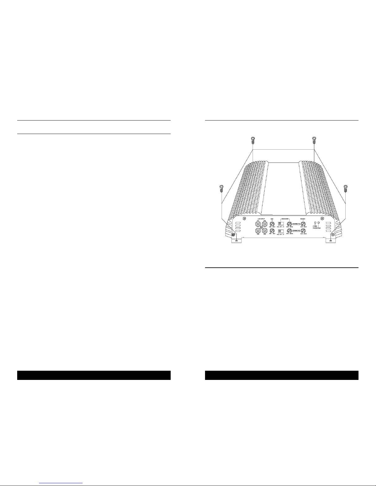
1. After reading precaution, decide where you are going to install the unit. Also,
see installation diagram.
2. Once the location has been determined, place the amplifier into position.
Using a felt tip pen or pencil mark the four holes to be drilled for mounting.
NEVER use the amplifier as a template for drilling. It is very easy to damage
the amplifier surface in this manner.
3. Remove amplifier. Drill four 3.5mm holes into mounting surface. If you want
to mount the amplifier to MDF or wood panel, drill four 3mm diameter holes
into mounting surface.
4. If possible, test the system to ensure it is operating correctly before final
mounting of the amplifier.
5. Mount the amplifier using the supplied 4 self threading screws.
Mounting

4
POLY-PLANAR • PO Box 409 • Hanover, MD 21076
Tel: (410) 761-4000 • Fax: (410) 761-6274 • www.polyplanar.com
5
POLY-PLANAR • PO Box 409 • Hanover, MD 21076
Tel: (410) 761-4000 • Fax: (410) 761-6274 • www.polyplanar.com
ME-400 Installation Instructions ME-400 Installation Instructions
• It is important to have good quality power and ground connections. Remember,
to complete an electrical circuit, the ground connection is just as important as
the positive power connection.
• Before any power connections are made, disconnect the ground cable at the
battery.
When the power supply lead, memory backup lead or ground lead are extended
use a 5mm 2(AWG5) or larger automotive grade cable which will withstand friction
and heat to safe grade against fires occurring as a result of short-circuiting.
GND: Connect the proper gauge ground wire to the amplifier “GND” terminal
and run the cable to the battery’s negative (-) terminal.
REM: Connect the remote wire ( power antenna output ) from the head unit to
the remote turn-on wire of the amplifier. If the head unit is not equipped
with a remote/antenna output, locate a wire that is controlled by the
accessory position of the key. It is important to have the amplifier turn
off with the radio or key. If the amplifier remains on, the result will most
likely be a dead battery.
BATT+: Connect the proper gauge power wire to the amplifier “B+” terminal.
Run wire to words the fuse holder that is no greater then 0.5 meter
from the battery. Remember, the fuse is to protect the safety of the car
in the case of a short. Connect fuse holder to battery, but do not install
fuse at this time.
Power Connections
This amplifier will accept low level inputs. Low level is the same as line level. The
low level signal is carried through RCA cables. It is preferred to use low level
inputs to the amplifier if the head unit is equipped with the low level outputs. If
not, you can use a “high to low converter” available through your local car audio
shop.
Connect the low level/line level RCA cables from the head unit, or signal
processor, to the line level input on the amplifier.
Input Connections

6
POLY-PLANAR • PO Box 409 • Hanover, MD 21076
Tel: (410) 761-4000 • Fax: (410) 761-6274 • www.polyplanar.com
7
POLY-PLANAR • PO Box 409 • Hanover, MD 21076
Tel: (410) 761-4000 • Fax: (410) 761-6274 • www.polyplanar.com
ME-400 Installation Instructions ME-400 Installation Instructions
This amplifier can operate in one, two or three channel mode. The minimum
impedance for stereo operation is 2 ohms per channel. The minimum impedance
for bridged operation is 4 ohms.
Connect right and left speaker wire to corresponding speaker output terminals
of the amplifier.
Be sure to have the positive wire from the speaker connected to the positive
speaker terminal of the amplifier.
Reversing any of these connections will result in the speaker cones moving out of
phase which causes bass cancellation.
See 2 channel & 4 channel Speaker wiring diagram.
Speaker Wiring 4 Speaker Stereo Mode
2 Speaker Bridge Mode
2 Speaker + 1 Subwoofer
See page 7 for Speaker Wiring Diagrams

8
POLY-PLANAR • PO Box 409 • Hanover, MD 21076
Tel: (410) 761-4000 • Fax: (410) 761-6274 • www.polyplanar.com
Poly-Planar products are warranted to be free of defects in materials and workmanship for a
period of two years. No finished goods or parts may be returned for repair or replacement
without Poly-Planar authorization. Goods received for any reason other than out-of-box
defect will be returned freight collect. To qualify as an out-of-box defect, the product must
be found defective within 30 days of retail sale. Please call Poly-Planar Customer Service
for authorization, which will take the form of an RMA (Return Merchandise Authorization)
number. Warranty is subject to proper installation and operation within published
specifications. Poly-Planar will repair or replace, at its discretion, any unit returned to
its factory and determined to be defective. Poly-Planar is not liable for consequential
damages.
Warranty
Each channel pair has a set of controls. Channels 1 and 2 adjust together; channels 3 and
4 adjust together.
1. Set to the “HP” (High Pass) position when the amplifier is used to drive a tweeter/mid-
range system. The frequencies below the crossover point will be attenuated at 12dB/
octave. Permits adjustment of the crossover frequency, by rotating the knob to select
any frequency between 40Hz to 250Hz as the crossover point.
2. Set to the “LP” (Low Pass) position when the amplifier is used to drive a subwoofer.
The frequencies above the crossover point will be attenuated at 12dB.octave. Permits
adjustment of the crossover frequency, by rotating the knob to select any frequency
between 40Hz to 250Hz as the crossover point.
3. Set to the “FULL” position when the amplifier will be used for driving full-range
speaker. The full frequency bandwidth ( 10Hz ~ 35KHz ) will be output to the speakers
without high or low frequency attenuation.
4. Level adjustment – The sensitivity adjustment is to allow the amplifier to work with
many different sources. It allows the input signal to vary between 200 millivolts to 6
volts from the head unit or other signal processor.
5. The “Bass Boost” function can be selected to increase low frequency output. This is
adjustable up to +18dB boost at 45Hz.
Adjustments
Specifications
RATED POWER @4ohm , THD 1% . . . . . . . . . . . . . . . . . . . . . . . . . . . . . . . . . . 100W x 4CH
RATED POWER @2ohm , THD 1% . . . . . . . . . . . . . . . . . . . . . . . . . . . . . . . . . . 150W x 4CH
RATED POWER @4ohm Bridged, THD 1% . . . . . . . . . . . . . . . . . . . . . . . . . . . . 300W x 2CH
MAXIMUM OUTPUT POWER . . . . . . . . . . . . . . . . . . . . . . . . . . . . . . . . . . . . . . . . . . . .800W
T.H.D @4ohm . . . . . . . . . . . . . . . . . . . . . . . . . . . . . . . . . . . . . . . . . . . . . . . . . . . . . . . 0.05%
T.H.D @2ohm . . . . . . . . . . . . . . . . . . . . . . . . . . . . . . . . . . . . . . . . . . . . . . . . . . . . . . . 0.08%
T.H.D @4ohm Bridged . . . . . . . . . . . . . . . . . . . . . . . . . . . . . . . . . . . . . . . . . . . . . . . . . . 0.1%
FREQUENCY RESPONSE @-1dB . . . . . . . . . . . . . . . . . . . . . . . . . . . . . . . . . . 10Hz ~ 35KHz
SIGNAL TO NOISE RATIO @ A weighted . . . . . . . . . . . . . . . . . . . . . . . . . . . . . . . . . . >90dB
INPUT SENSITIVITY . . . . . . . . . . . . . . . . . . . . . . . . . . . . . . . . . . . . . . . . . . . . . 200mV ~ 6.0V
INPUT IMPEDANCE . . . . . . . . . . . . . . . . . . . . . . . . . . . . . . . . . . . . . . . . . . . . . . . . .20Kohm
LOW PASS FILTER . . . . . . . . . . . . . . . . . . . . . . . . . . . . . . . . . . . . . . . Variable 40Hz ~ 250Hz
HIGH PASS FILTER . . . . . . . . . . . . . . . . . . . . . . . . . . . . . . . . . . . . . . Variable 40Hz ~ 250Hz
BASS BOOST @45Hz . . . . . . . . . . . . . . . . . . . . . . . . . . . . . . . . . . . . . . . . . . . . . . 0 ~ 18 dB
FUSE RATING . . . . . . . . . . . . . . . . . . . . . . . . . . . . . . . . . . . . . . . . . . . . . . . . . . . . . . 20A x 2
DIMENSION ( W x H x D )mm . . . . . . . . . . . . . . . . . . . . . . . . . . . . . . . . . . . . .415 x 55 x 240
NOTE : Specification & design subject to change without notice for improvements.
Other manuals for ME-400
2
Table of contents
Other poly-planar Amplifier manuals

poly-planar
poly-planar ME-51 User manual

poly-planar
poly-planar ME60BT User manual

poly-planar
poly-planar ME70BT User manual

poly-planar
poly-planar ME-50 User manual

poly-planar
poly-planar ME-400 User manual

poly-planar
poly-planar MZ-100 User manual

poly-planar
poly-planar ME-400 User manual

poly-planar
poly-planar ME-52 User manual

poly-planar
poly-planar ME-60 User manual

poly-planar
poly-planar ME-400D User manual