Poly Pong ALL WEATHER TABLE User manual

ASSEMBLY MANUAL
ASSEMBLY MANUALASSEMBLY MANUAL
ASSEMBLY MANUAL
Rev.3/12/2011
©
®
www.polypong.com
ALL WEATHER TABLE TABLE

1. Attach A-Frames tothe Dolly Floor as shown. Use a long bolt, two washers,
and a lock nut at each of the four positions as shown in Fig. 2. Make sure that the
anglebrackets at the top are positioned as shown in Fig.3.
2. Select four Socket head cap screws from the box and screw them into the top bar nuts locat-
ed on each end of the top bars. This will clean out any paint. Remove the screws once the
threads are clean.
Fig. 2
1. Locate each of the parts shown in Fig. 1.
1
DOLLY ASSEMBLY
Item# Description qty.
1. Table support arm 2
2. Castor Wheels 4
3. A-Frame 2
4. Hinge Brackets 2
5. Dolly Floor 1
6. Top Bar 2
7. Legs 4
8. U-clamp 12
9. Bar Block 4
10. Left bumper block 4
11. Right bumper block 4
12. Spacer table
support 4
13. Parts & tool Box
Fig. 3

4. The four casters need to be mounted to the A-
Frame. A washer is shown being placed above
the bar to protect the paint. Repeat with each
castor wheel. Fig. 5, 6.
2
Fig. 6
Fig. 8
Fig .7 5. Bolt each table support arm
to the dolly using the hardware
shown. Place a washer onto a
long bolt, then insert it through
the A-Frame, then another
washer, then go through the
table support arm. Put another
washer on the protruding end
of the bolt, and secure with one
5 cont. of the lock nuts. To do this,
you may have to temporarily loosen
the bolts between the A-frames and
the dolly floor. Repeat for the other
side of the table support arm. Do the
same for he other side of the dolly as
shown. e-tighten all bolts. Fig. 7, 8.
This completes the dolly assembly.
Fig. 5
3. Mount the two top bars to the angle
brackets on the A-frames using the longer,
14mm hex head nuts you just used to clean
the threads and two washers as shown.
Fig.4

3
Table Tops Assembly
6. Place the YELLOW quarter table piece face down on a smooth clean surface so
the top surface won’t be scratched. Locate a leg assembly, two hinge assemblies,
four U-clamps, two bar blocks, a left bumper block and a right bumper block and
place them onto the bottom surface of the table as shown (Fig. 9). Use 8Mx10mm
bolts unless otherwise noted.
7. Mount the leg (7) center support with four bolts. Secure the leg pivot bar to the
table top using two U-clamps ( round mounting holes), and four bolts as shown (8a).
8. Mount the two hinge assemblies (4) using five bolts each.
9. Mount the two table support bar U-clamps (8b) ( oblong mounting holes), one on
each side of the table. Place spacer (12) between U-clamp and the table (Fig. 9
insert). Use longer, 14mm bolts. They should not be tightened at this point.
10. Mount the two bar blocks (9) and the left and right bumper blocks (10, 11) on
the bottom edge as shown. You will need eight flat head socket drive bolts for
these. This completes the YELLOW table top assembly.
11. Place the GREEN quarter table piece down on a clean surface face down and
adjust it to the left side of the YELLOW table piece. Place a leg assembly (7) and
two U-clamps (8a) on the table as shown in Fig. 10. Use 12 bolts. Secure tightly.
Fig.9

Fig.20
Fig. 1012. Add the left and right
bumper blocks (10, 11) as
shown. Use the flat head
socket drive screws for
these.
Repeat the same procedure
for the BLUE table top as
you did for the YELLOW
table top, and on the RED
table top as you did on the
GREEN table top. The
four tops should now look
like Fig. 11.
Fig. 11
4
Check the
following:
LEGS
are they posi-
tioned correct-
ly?
HINGES
are they orient-
ed correctly?
U-CLAMPS
There should
be 8 for legs
and 4 for the
table support
arms.
Bumper
blocks
Have you
placed 4 left
and 4 right
ones?
Bar Blocks
There should
be four.

13. Carefully lift the YELLOW-GREEN
table tops by the two joining short sides to
the vertical position. This will allow you
to fold the two quarter tables with their top
sides together. Leave them spread at a
slight angle so that they won’t fall. Repeat
for the BLUE-RED table tops. Fig. 12.
Fig. 12
14. Lower one table support arm and
using two people, carefully lift the
YELLOW-GREEN table top assembly
onto the dolly. FIG 13. Now lift the
table support arm and while two people
1. are lifting the table tops, a third
person
should carefully loosen the U-clamps
Fig. 13
secure them around the bearings of the
support arms on each side. Fig. 14. Re-
peat the procedure for the BLUE-RED
table assembly on the other side. This
completes the assembly of your table.
Fig. 15. Add a stretch strap from the YEL-
LOW leg to the BLUE leg across the top
of the tables and one across the front near
the bearing blocks for transporting the table.
Fig. 14
5
Fig. 15

1. Remove the two stretch straps from
across the table by undoing the
Velcro. Remove the top bumper.
Lock the wheels. When setting up out-
of-doors on soft ground, put a solid
surface under the legs and dolly
wheels to prevent the table from
pushing into the ground. Lock wheels
in place.
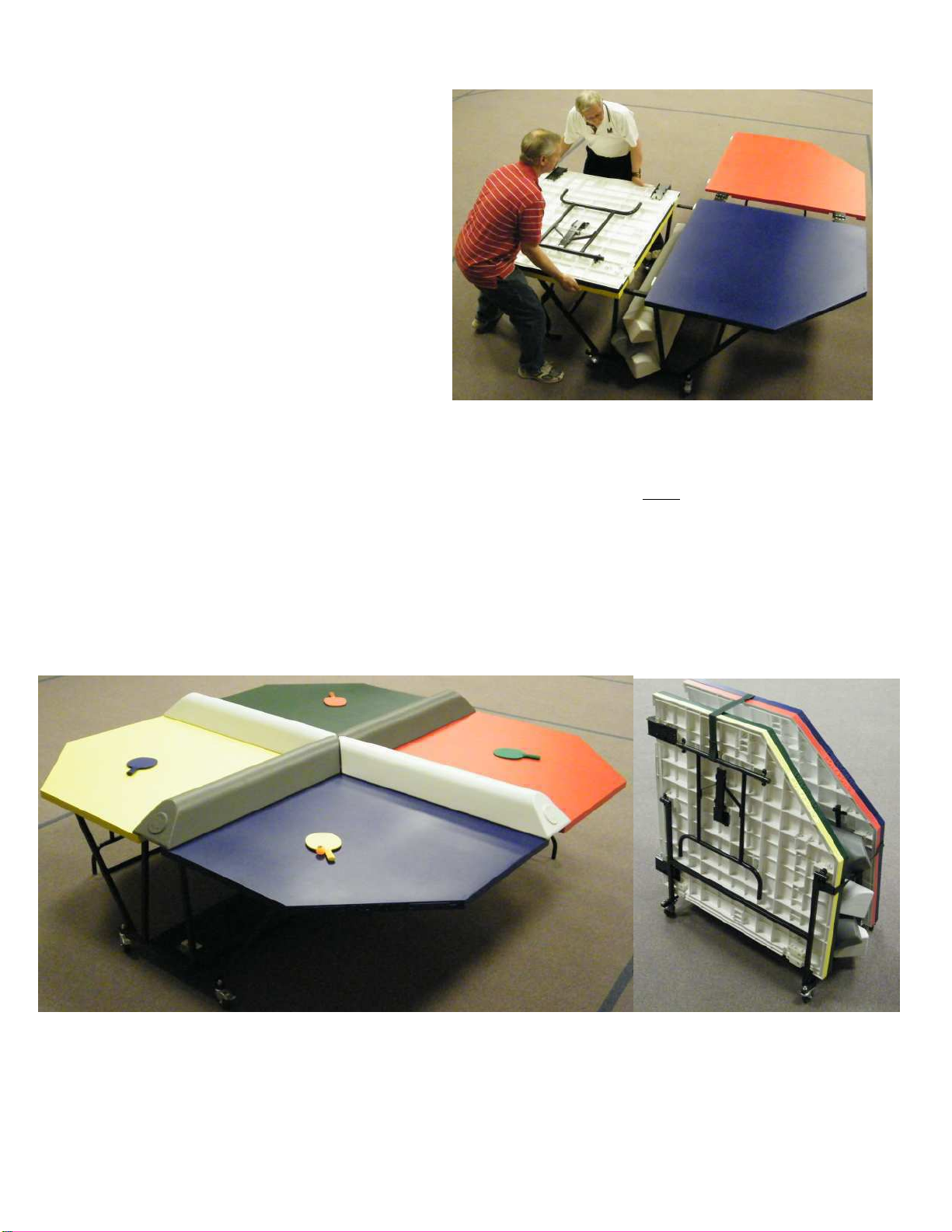
2. With one person on each side of
the table, extend the leg out about 45
degrees, then swing the tabletop out
and rotate its inner edge upward
pivoting around the table support arm
so that its edge goes over the the top
of the dolly top bar and fits down
securely in the second groove on the
underside of table . Rotate the
supporting leg down extending the leg
so that the leg locks in place. The
table should be level and solid when
positioned correctly. If the leg is
trapped by the table support arm,
raise the table again to the vertical
position, extend the leg out so it is
free from the cross bar of the table
support arm, and repeat the
procedure.
3. Lift the leg on the upper tabletop to
vertical position and rotate the table
(red or green) by the legs, pivoting
the table on its hinges until the table
top has rotated 180 degrees. The table
is now fully extended and the leg
extended, with its leg lock in place,
and the feet resting on the floor.
4. Repeat steps 2 and 3 for the other
side of the table. The table should
now be fully opened and all legs
firmly on the floor.
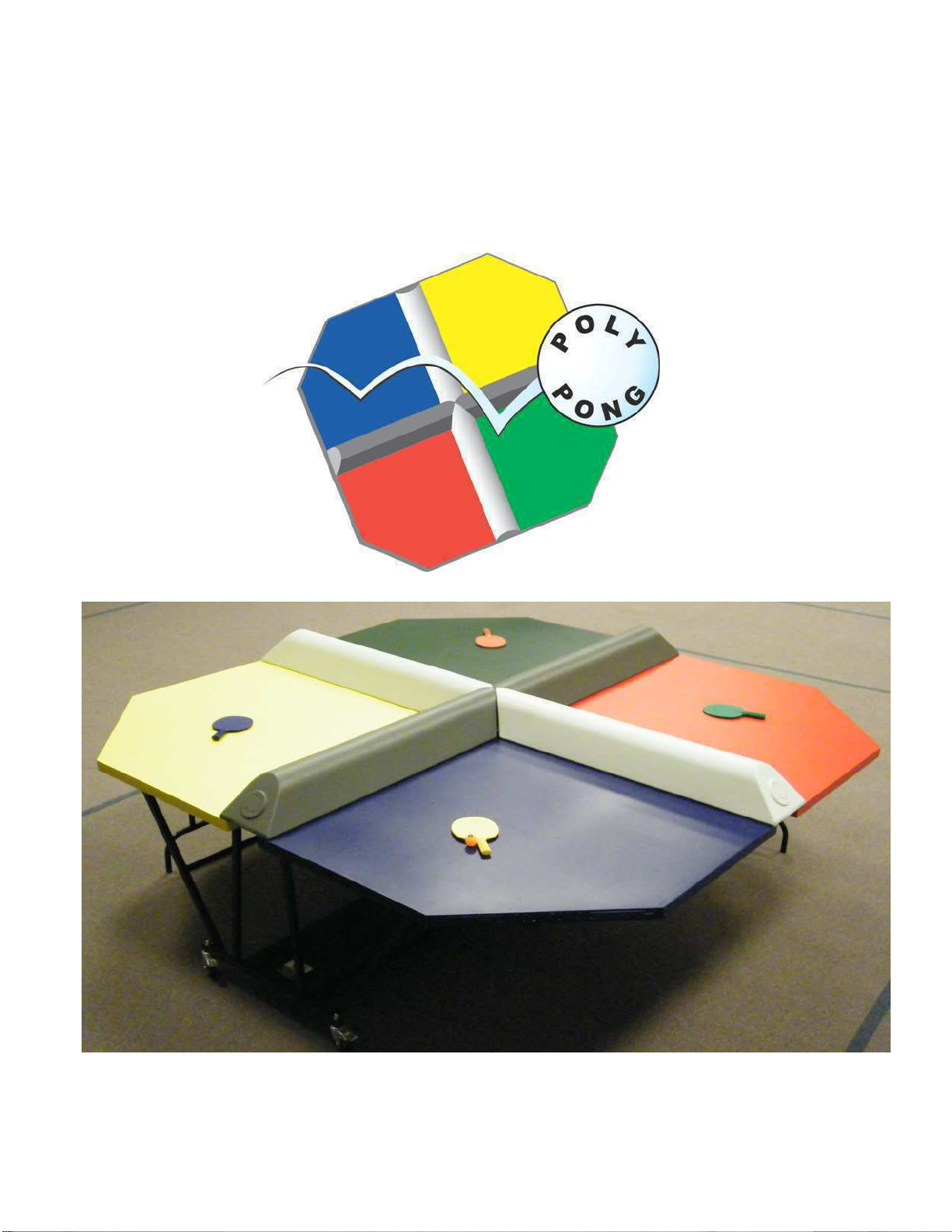
POLY PONG SETUP INSTRUCTIONS
6

7
6. The table is taken down by following these instructions in reverse order. Re-
move the bumpers. Fold the two table tops (GREEN and RED) onto the YELLOW
and BLUE table pieces. You must first unlock the legs and fold them up before you
attempt to lift the stacked table pieces onto the dolly. Otherwise you cannot lift
them. Remember to use two individuals, one on each side. Replace the stretch
rubber straps across the tops and front end of the table so the table halves cannot
accidentally open up and fall down during transport. Store the bumpers on the rack
with three on the bottom and one on the top.
IMPORTANT SAFETY NOTE:
Lift and pivot table top by leg only! Avoid pinching your fingers between the
two table pieces!!
5. Take the remaining three bumpers
from their stowed location and place
the bumpers onto the table in the
gaps between the tables with the
points meeting in the center. The
two white bumpers should be across
from each other separated by the
two gray bumpers.
Table of contents
Popular Indoor Furnishing manuals by other brands

Accentrics Home
Accentrics Home DS-D470-180 Assembly manual

BorMann
BorMann BSR3001 Assembly instructions

Forte
Forte RMRS924E1 Assembling Instruction

Argos
Argos Hygena Charlie 323/2349 Assembly instructions

Furniture of America
Furniture of America CM7867D Assembly instructions

DGL
DGL LUIS Assembly instructions