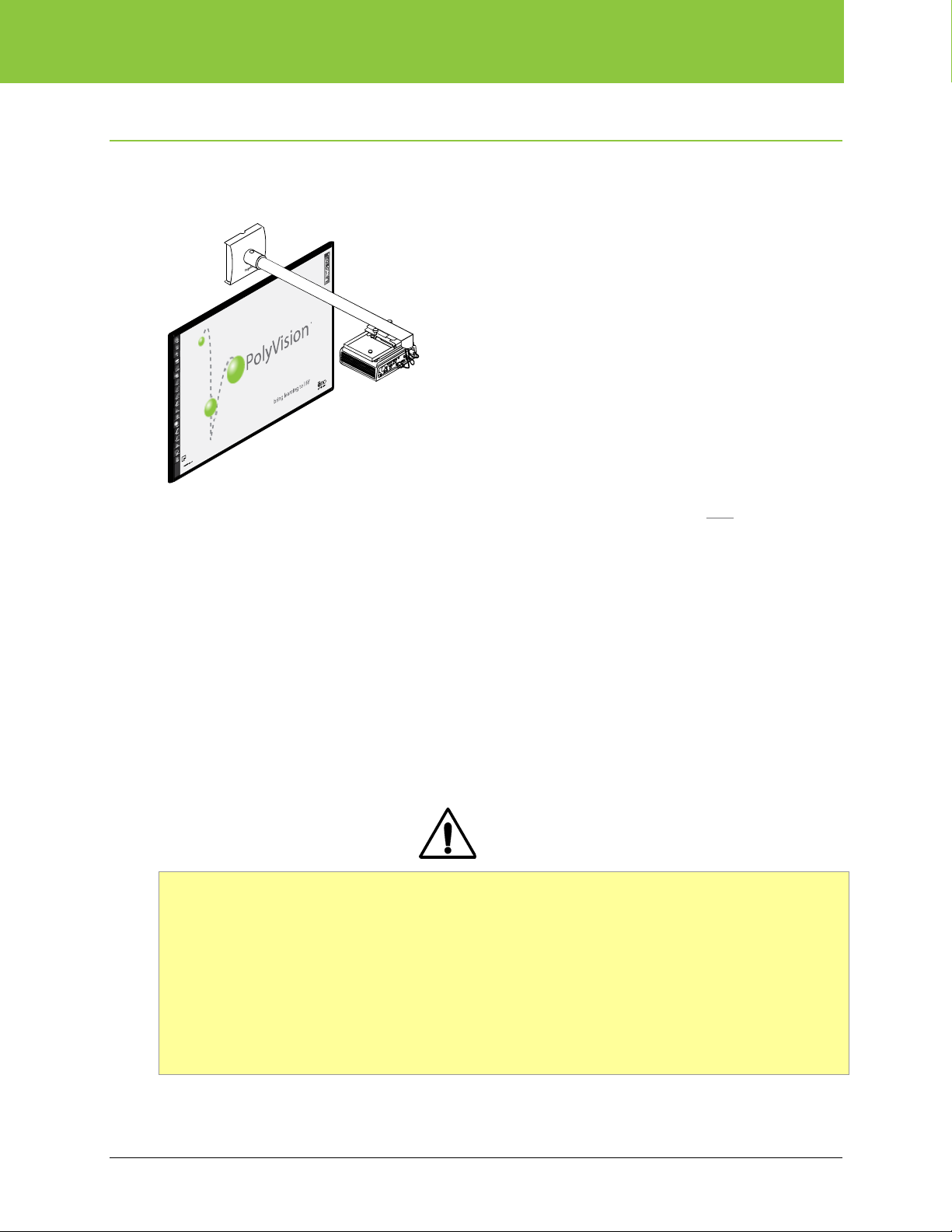
ēno one Fixed Wall Arm
2 Installation and Operation Guide
Table of contents
Overview ........................................................................................................................................................ 3
Important considerations ............................................................................................................................ 3
Tools and supplies ......................................................................................................................................... 5
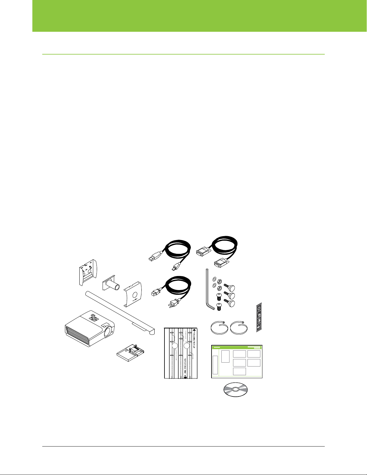
What comes in the box............................................................................................................................... 5
Required items ........................................................................................................................................... 6
Suggested hardware for the wall bracket.................................................................................................... 7
Install the fixed wall arm ................................................................................................................................. 8
Step 0: Install the whiteboard ..................................................................................................................... 8
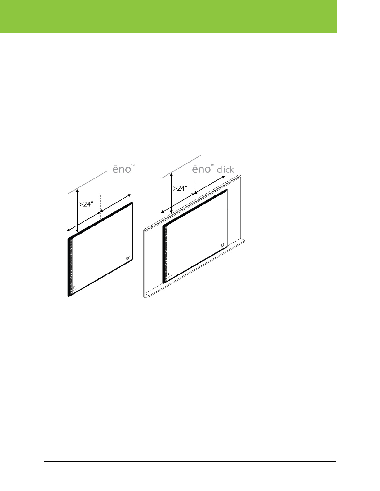
Step 1: Position the fixed wall arm.............................................................................................................. 8
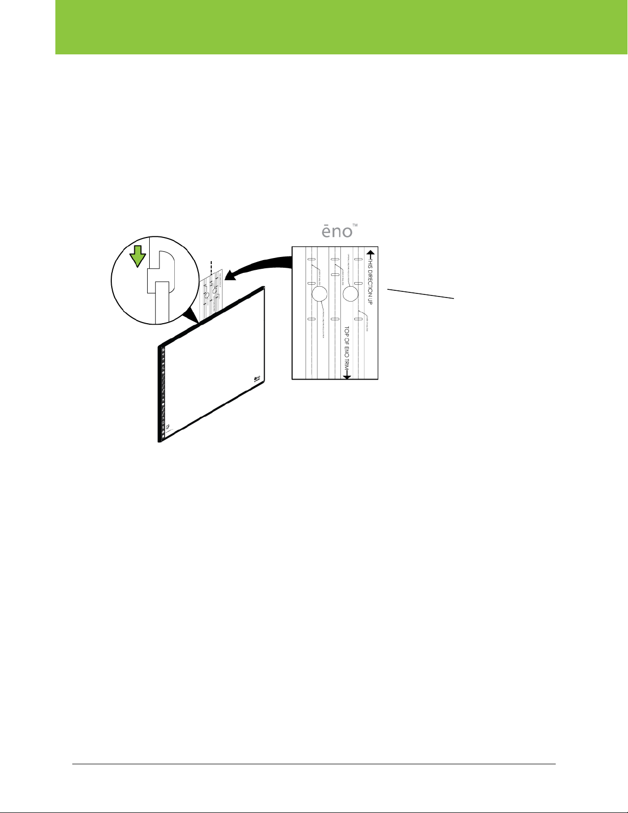
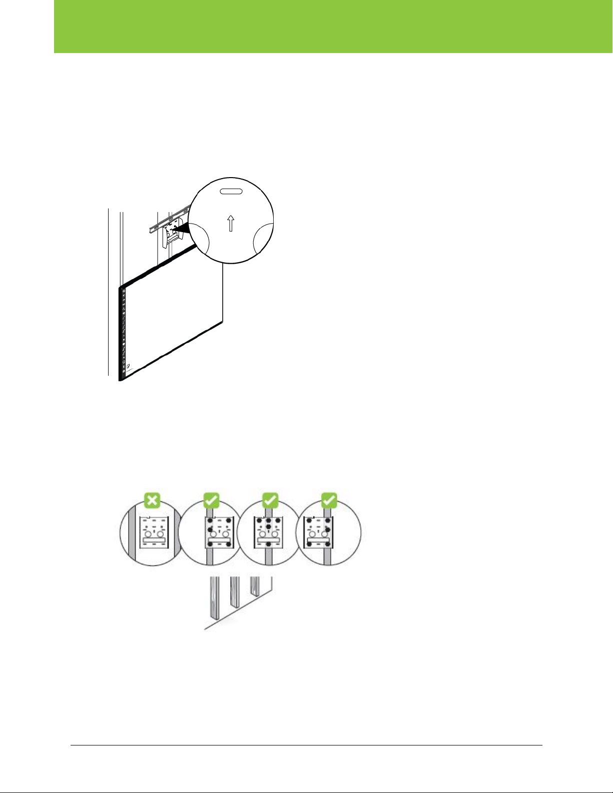
Step 2: Locate and mark fastener locations on the wall.............................................................................. 9
ēno classic interactive whiteboards.......................................................................................................... 9
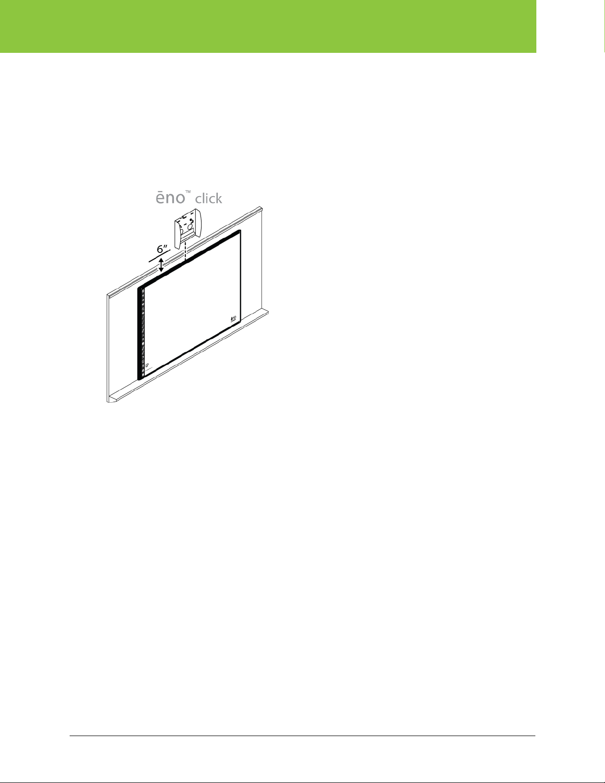
ēno click interactive whiteboards ........................................................................................................... 10
In-wall cable routing............................................................................................................................... 10
Step 3: Fasten the wall bracket to the wall ............................................................................................... 11
Wood stud installation ........................................................................................................................... 11
Metal stud installation ............................................................................................................................ 12
Hollow concrete/brick wall installation.................................................................................................... 13
Solid concrete/brick wall installation....................................................................................................... 13
Step 4: Assemble the boom arm, cover, and breakaway plate ................................................................. 14
Step 5: Fasten the breakaway plate to the boom arm ..............................................................................15
Step 6: Fasten the boom arm/breakaway assembly to the wall bracket ................................................... 16
Step 7: Prepare the projector adapter plate.............................................................................................. 16
Step 8: Fasten the projector mount to the boom arm ............................................................................... 17
Step 9: Fasten the projector adapter plate to the projector....................................................................... 18
Step 10: Fasten the projector to the boom arm ........................................................................................ 19
Step 11: Connect cables to the projector and add the magnetic icon strip to the whiteboard .................. 20
Cable strain relief ................................................................................................................................... 20
Step 12: Power on the projector............................................................................................................... 21
Projector adjustment and driver installation .................................................................................................. 22
Step 13: Troubleshooting projector focus and alignment..........................................................................22
Focus .................................................................................................................................................... 22
Image size ............................................................................................................................................. 22
Image location (left to right).................................................................................................................... 23
Image tilt................................................................................................................................................ 23
Image location (up and down)................................................................................................................ 24
Image location (up and down)................................................................................................................ 24
Final check ............................................................................................................................................ 25
Step 14: Install the PolyVision Driver Projector Add-in .............................................................................. 25
Index ............................................................................................................................................................ 26