POMCube iCAN Mini 3500 User manual

iCAN Mini
User Manual
Model: iCAN Mini 3500

Important Safety Instructions
Please keep this manual for future reference.
This manual contains all safety, installation and operating instructions for iCAN Mini - an integration of solar charge
inverter and controller.
Please carefully read all instructions and precautions in the manual before installation and usage.
T
here is a non-safety voltage inside the iCAN Mini. In order to avoid physical injury, users shall not disassemble
it themselves. If any repair is needed, please contact professional maintenance personnel in our company.
Please do not place the iCAN Mini in the places where the children can touch.
Please do not install the integrated machine in harsh environment where is damp, greasy, inflammable and
explosive, or dust is excessively accumulated.
The utility input and AC output are high voltage, so please do not touch the wire connection points.
When the iCAN Mini is working, the temperature of the machine case will be very high, please do not touch it.
When iCAN Mini is working, please do not open the terminal protection cover.
It is recommended to install appropriate fuses or circuit breaker on the outside of the iCAN Mini.
Please be sure to disconnect the fuses or circuit breaker near the PV array, utility power and battery terminals
before installing and adjusting the connected wire of the iCAN Mini.
After installation, check if all wire connection is tight in order to avoid the risk of heat accumulation due to bad
connection.
The iCAN Mini is off-grid type. It is strictly forbidden to be connected to the grid, or else the machine will be
damaged.
At present, it is allowed that the iCAN Mini only work singly. It is strictly forbidden for multiple machines to
output in parallel or in series, or else the iCAN Mini will be damaged.

2
Table Of Contents
1. General Information...................................................................................................................... 3
1.1 Product overview and features.............................................................................................. 3
1.2 Basic system introduction .................................................................................................... 4
2. Installation Instructions.............................................................................................................. 6
2.1 Installation precautions ........................................................................................................ 6
2.2 Connecting wire specifications and circuit breaker model selection ....................................... 8
2.3 Installation and Connection................................................................................................ 10
3. Working mode........................................................................................................................... 14
3.1 Charge mode ..................................................................................................................... 14
3.2 Output mode...................................................................................................................... 15
4. Instruction for parameter setting.............................................................................................. 17
4.1 Parameter viewing............................................................................................................. 17
4.2 LED status description....................................................................................................... 17
4.3 Parameter setting............................................................................................................... 18
4.4 Parameters of different types of battery............................................................................... 23
5. Other functions ......................................................................................................................... 23
5.1 Function of dry contact ...................................................................................................... 23
5.2 RS485 communication function.......................................................................................... 24
5.3 CAN communication function............................................................................................ 24
5.4 USB communication function ............................................................................................ 25
6. Protection.................................................................................................................................. 25
6.1 Protection functions........................................................................................................... 25
6.2 Fault code meaning............................................................................................................ 26
6.3 Partial troubleshooting measures........................................................................................ 28
7. System maintenance.................................................................................................................. 29
8. Technical parameters................................................................................................................ 30

3
1. General Information
1.1 Product overview and features
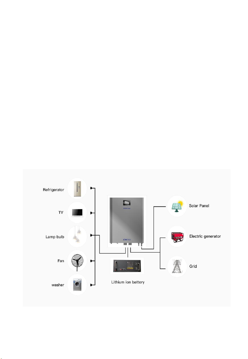
The iCAN Mini series is a new hybrid charge control inverter device, which integrates solar energy,
utility charge and AC output. It features high response speed, high reliability and high industrialization
standard, etc., by adopting DSP design and advanced control algorithm. It provides four charge modes:
Solar Only, Utility Priority, Solar Priority and Mixed charging. Two output modes can be selected: inverter
and utility, which meet different application requirements.
The solar energy charge module adopts the latest optimization MPPT tracking technology to quickly
track the maximum power point of PV array in any environment, obtaining the maximum energy of the
solar panel in real time.
The AC-DC charge module adopts advanced control algorithm to achieve fully digital voltage and
current double closed loop control with high control accuracy and small size. The AC voltage input range
is wide, and the input/output protection functions are complete, which achieve to charge and protect battery
stably and reliably.
Based on the fully digital intelligent design, DC-AC inverse transformation module adopts advanced
SPWM technology to output pure sine wave to convert DC power into AC power, which is applicable for
household appliances, power tools, industrial equipment, electronic audio & video, and other AC loads.
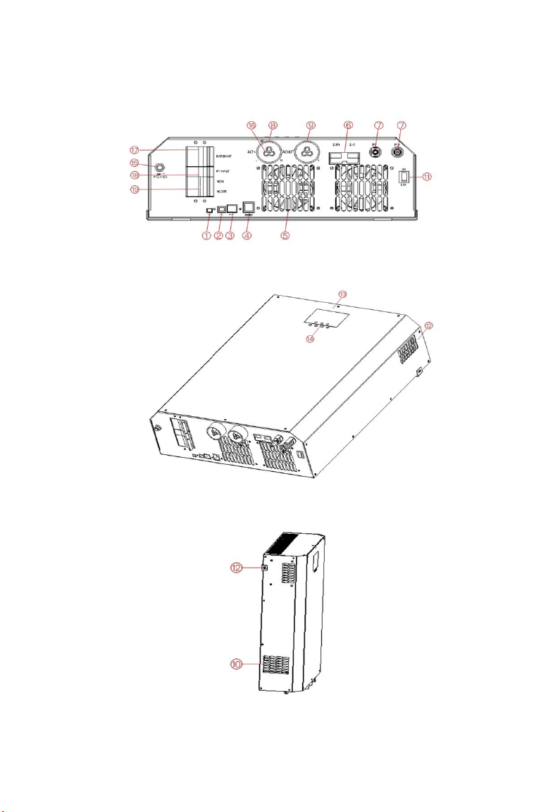
The product adopts segment LCD display design to display the run data and operation state of the system
in real time. Comprehensive electronic protection function ensures that the overall system is safer and more
stable.
Features:
1. When there is no battery, the PV can supply power to the load separately, but can only drive half of the
rated power to the maximum.
2. It adopts full digital voltage and current double closed loop control, advanced SPWM technology, pure
sine wave output.
3. Two output modes: Utility bypass and inverter output, thereby providing uninterrupted power supply.
4. Four charging modes optional: Solar Only, Utility Priority, Solar Priority and Mixed charging.
5. Maximum power point tracking (MPPT) technology ensures a tracking efficiency not less than 99.9%.
6. The LCD screen with an easy-to-understand operationinterface presents a dynamic display of system,
and 3 LED indicators indicate working status of the systemat all time.
7. The ON/OFF rocker switch button allows for an independent control of AC output, reducing
unnecessary losses, without affecting battery charging by PV or utility power.
8. Intelligent speed-adjustable fan for efficient heat dissipation and extended system life.
9. PV can activate a lithium battery. Therefore, it is compatible with lead-acid batteries and lithium
batteries.
10. Multiple protection features ,it offers 360°all-round protection.

4
1.2 Basic systemintroduction
iCAN Mini can be applied to a system typically including:
1. Solar panel: Converting light energy into DC power, charging the battery through the iCAN Mini. It
can also be directly inverted into AC power to supply power to the load.
2. Generator or utility: Connected to the AC input, it can supply power to the load and charge the battery
at the same time. Ifthe generator or utilityis not connected, the system can also operate normally. At this time,
the load power is provided bythe battery and the PV modules.
3. Battery packs: The function of the battery is to ensure the normal supply ofthe load when the solar
energyis insufficient and there is no utilitysupply.
4. Home Appliances: Compatible with a variety of household and office loads, including refrigerators,
lamps, televisions, fans, air conditioners and other AC loads.
5. iCAN Mini: the “central hub” of energy conversion.
The specific system application method depends on your requirements.

5

6
○
1
CAN communication port
○
11
ON / OFF
○
2
USB communication port
○
12
Fan air vent
○
3
RS485 communication port
○
13
LCD screen
○
4
Stem node ports
○
14
Buttons
○
5
Inverter + MPPT charge fan
○
15
Instantaneous utility
overcurrent protection
○
6
Battery input wire terminal
○
16
Ground connection screw
hole
○
7
Solar input wire terminal
○
17
Battery switch
○
8
AC input wire terminal
○
18
Solar switch
○
9
AC load output wire terminal
○
19
Switches of AC input and
output
○
10
Utility charge fan
2. Installation Instructions
2.1 Installation precautions
Please read this manual carefully before installation to be clear about the installation steps.
Please be very careful when installing the battery. When installing lead-acid battery, protective
glasses should be worn. Once contacting the battery acid, please rinse it with clean water in
time.
Avoid placing metallic objects near the battery in order to prevent the battery from short
circuiting.
Acid gas may be generated when the battery is being charged, so good ventilation in
surrounding environment should be ensured.
When installing the cabinet, it is sure to leave enough space in the perimeter of the iCAN Mini
for heat radiation. Do not install the iCAN Mini and lead-acid battery in the same cabinet in
order to avoid acid gas generated by the working battery corroding the iCAN Mini.
Only charge the battery types that are in conformity with this iCAN Mini.
Bad connection points and corroded wires may cause extreme heat to melt the wire insulation
layer, burn the surrounding materials, and even cause fire, so it is sure to tighten the
connection points, and it is best to secure the wires with the cable ties in order to avoid the
loose connection points caused by shaking the wires when moving and applying.
The system connection wire is selected in accordance with a current density of not more than
5A/mm2.
Avoid direct sunlight and rainwater infiltration when the machine is installed outdoor.

7
After turning off the power switch, there is still high voltage inside the iCAN Mini. Please do
not open or touch the internal devices. After the completion of capacitance discharge, related
operations can be carried out.
Please do not install the iCAN Mini in harsh environments where is damp, greasy,
inflammable and explosive, or dust is excessively accumulated.
It is forbidden to connect reversely the polarity of the input terminal of the battery of this
product, or else it is easy to damage the equipment, or any unforeseen danger will be occurred.
The utility input and AC output are high voltage, so please do not touch the wire connection
points.
When the fan is working, please do not touch it in order to avoid injury.
Do not reverse the PV polarity.

8
2.2 Connecting wire specifications and circuit breaker model selection
Methods of connecting wire and installation must abide by national and local electrical specification
requirements.
Recommendation for PV array connecting wire specifications and circuit breaker model selection:
Because the output current of the PV array is influenced by the type, connection method and illumination
angle of the solar cell module, the minimum wire diameter of the PV array is calculated in accordance with
the short circuit current of the PV array. Please refer to the short circuit current value in the solar cell
module specifications (the short circuit current remains the same when the solar cell module is connected in
series; the short circuit current is the total of the short circuit currents of all parallel assemblies when
connected in parallel). The short circuit current of the array cannot exceed the PV maximum input current
Please refer to the following table for the PV input wire diameter and switch:
Model No.
Recommended wire
diameter of PV array
Recommended air switch or circuit
breaker model
iCAN Mini 3500
10mm2/8AWG
2P—63A
Note: The voltage connected in series must not exceed the maximum PV input open circuit voltage of 145V.
Please refer to the following table for the recommended AC input wire diameter and switch:
Model No.
Recommended wire
diameter of utility power
Recommended air switch or circuit
breaker model
iCAN Mini 3500
10 mm2/7AWG
2P—63A
Note: There is corresponding circuit breaker at the wire connection points of the utility power, so there is no
further circuit breaker needs to be added.
Recommended battery input wire diameter and switch model selection
Model No.
Recommended wire
diameter of battery
Recommended air switch or
circuit breaker model
iCAN Mini 3500
25mm2/4AWG
2P—100A
Recommended AC output connecting wire specifications and circuit breaker
model selection
Model No.
Recommended wire diameter
of load
Recommended air switch or circuit
breaker model
iCAN Mini 3500
10mm2/7AWG
2P—40A
Note: The wiring diameter is for reference only. If the distance between the PV array and iCAN Mini or

9
iCAN Mini and the battery is far, the thicker wire rod can reduce the voltage decline to improve the system
performance.
Note: The above wiring diameter and circuit breaker are only recommended. Please select the proper wiring
diameter and circuit breaker according to actual situation.

10
2.3 Installation and Connection
Installation steps:
Step 1: Determine the installation location of iCAN Mini, such as the wall surface, as well as the heat
radiation space. When installing the iCAN Mini, ensure that there is sufficient air flowing through the
radiation fins of the iCAN Mini. The left and right air outlets of the iCAN Mini should leave at least 200mm
space in order to ensure heat radiation by the air natural convection. Refer to the above installation diagram
of the whole machine.
Warning: Danger of explosion! Do not install the iCAN Mini and lead-acid battery in the same
confined space! Do not install in a confined place where battery gas may accumulate.
Step 2: Connect wires.

11
Installation of AC output, AC output wire port and grounding.
①Take out the port and disassemble it as follows:
②Thread as follows:
③Fix cables of different colors to the proper positions in the connector using allen driver: red –L; green
–N; yellow and green –PE.

12
Note:
Image 3: finished proper connection
Image 4: three positions with signs printed on the port.
④Assemble t parts as follows, as per instructions shown.
⑤Installation finished.

13
WARNING
①The utility input and AC output are high voltage, please ensure the disconnector or protector is
switched off before connecting.
②Be cautious of your own safety throughout the connection. DO NOT Switch on the disconnector or
protector, ensure the positive and negative poles of all parts are connected properly.
③A disconnector must be installed for the battery, please refer to Section 2.2 (Connecting wire
specifications and circuit breaker model selection) for the right products.
④If this product is installed in areas with frequent thunderstreak, an external lighting arrester is
suggested for solar input.
Step 3: Ground connection.
If there is grid input to iCAN Mini, grounding must be performed. The dedicated grounding terminal on
iCAN Mini must be grounded reliably with a cable that is thick enough (the cross-sectional area of the wire
should be no less than 4mm2). The grounding point should be as close as possible to iCAN Mini. The shorter
the grounding wire, the better.
Step 4: Terminal connection
Connect the AC IN, LOAD, and PV terminals to the AC IN, LOAD, and PV terminal blocks of iCAN Mini
to ensure that the terminals are securely connected.
Step 5: Double Check.
Double check that the wiring is connected correctly. In particular, check whether the poles of battery input,
PV input are connected correctly, and whether the AC input is incorrectly connected to AC output.
Step 6: Activate iCAN Mini.

14
Switch OFF the circuit breaker at the battery end, then the rocker switch ON the right side of iCAN Mini.
The "AC / INV" flashes to indicate that the inverter is working normally. Again, switch OFF the circuit
breaker of PV array and utility power. After the AC is outputted normally, turn on AC load one by one, to
avoid the protection action caused by a large momentary impact from the simultaneous startup of the load.
Therefore, iCAN Mini will perform normally according to the set mode.
Note: If power is supplied to different AC loads, it is recommended to first power a load with a large inrush
current. After the load is stable, turn on the load with a smaller inrush current.
Note: If iCAN Mini does not work properly or the display of LCD/indicator is abnormal, refer to Section 6
for troubleshooting.
3. Working mode
3.1 Charge mode
Solar energy first: Solar power is primary source for charge of battery, and charge is supplied by
utility power only when solar power is not available. This mode is to fully utilize solar power in the
daytime and utility power in nighttime to maintain the battery capacity, and it is suitable for the place
in which power grid is relatively stable with expensive electricity price.
Utility first: Utility power is primary source for charge of battery, and charge is supplied by solar
power only when utility power is not available.

15
Mixed charging (Solar and utility): Charge is completed with hybrid supplement of solar power
and utility power. Solar MPPT is primary source for charge of battery, and utility power is supplied
when solar energy is not sufficient. When solar energy is sufficient, charge source is switched from
utility power to solar energy. This mode is characterized by short time, and is suitable for the place in
which power grid is not stable to supply sufficient backup power source at any time.
Only Solar: Charge is completed with solar power without utility power. This mode is characterized
by energy-saving that all the battery power is supplied by solar energy, and it is suitable for the place
in which light condition is good.
3.2 Output mode
Solar first: load is supplied by solar energy and battery, and various charge modes and output modes
are available. When solar first is selected, it will maximize the usage of solar energy to fulfill the
energy-saving and emission-reduction.
(1) When the battery is disconnected or disabled, load can be directly supplied with startup of

16
photovoltaic panel if the load power is less than the power supplied by solar energy, but the
maximum inversion load shall be the half of rated power.
(2) When solar power is not available, utility power is switched for supplement. This mode is to
maximize the usage of solar energy and maintain the battery capacity at the same time, and it is
suitable for the place in which power grid is stable relatively.
Utility first:Only when utility power is not available, power is supplied by inverter as backup UPS.
This mode is for the place in which power grid is not stable.
Inverter first:When the battery is under-voltage, power is supplied by utility power. This mode is
characterized by maximum usage of DC energy, and it is suitable for the place in which power grid is
stable.

17
4. Instruction for parameter setting
4.1 Parameter viewing
4.2 LED status description
Press the “UP” and “DOWN” keys on the LCD screen to scroll through the page to view the
machine parameters.
Page
number
Parameters on the left side
of the screen
Parameters in the
middle of the screen
Parameters on the right
side of the screen
1
Ac input voltage
Fault code
Output voltage
2
PV input voltage
3
PV charge current
4
Battery input voltage
Output frequency
5
Battery charge current
Load current
6
Ac charge current
Load active power
7
Temperature
Load apparent power
8
Software version
Software version
LED 1
Yellow
AC/INV
Always on: utility output
Flashing: inverter output
LED 2
Green
CHARGE
Flashing: the battery is charging
Always on: charging is completed
LED 3
Red
FAULT
Always on: Fault status (output uninterrupted)
Flashing: Alarm status (output interrupted)

18
4.3 Parameter setting
Operating instruction for keys: press ‘SET’ to enter or exit setup menu, then Parameter #00 will flash. Press
‘UP’, ‘DOWN’ and ‘ENT’to edit the parameters when parameter is flashing, then press ‘ENT’ to confirm
changes, finally press ‘ENT’ to exit.
Parameter
No.
Parameter
name
Setting
option
Description
Detailed description
00
Exit setting
menu
[00] ESC
Exit setup menu
01
Output
source
priority
[01] SOL
Solar first
Solar first mode, when solar
power is not available or the
battery capacity is lower than the
settings of parameter [04] power
source is switched to utility
power.
[01] UTI
Utility first
Utility first, power source is
switched to inverter only when
utility power is not available.
[01] SBU
(default)
Inverter first, default
Inverter first, power source is
switched to utility power only
when battery is under-voltage or
the battery capacity is lower than
the settings of parameter [04].
02
Output
Frequency
[02] 50Hz
230V
Bypass automatically adapts.
When utility power is available,
bypass automatically adapts the
frequency of utility power. When
utility power is not available, the
output frequency can be set via
menu. Default frequency: 230V –
50.0Hz; 120V ~60.0Hz
[02] 60Hz
120V
03
AC Input
Voltage
Range
[03] APL
(default)
Applicable on 230V
device ONLY
AC Input Voltage Range.
Setting range (230V): 90V~280V
Setting range (120V): 90V~140V
[03] UPS
Applicable on 230V
device ONLY
AC Input Voltage Range.
Setting range (230V):
170V~280V
Setting range (120V): 90V~140V

19
04
Battery
voltage to
line
[04] 46.0V
(default)
Parameter [01] = SOL/ SBU,
voltage of battery is lower than
settings, output is switched from
inverter to utility power.
Setting range: 44V~52V
05
Battery
voltage to
inverter
[05] 56.0V
(default)
Parameter [01] = SOL/ SBU,
voltage of battery is higher than
settings, output is switched from
utility power to inverter.
Setting range: 48V~60V
06
Charger
source
priority
[06] CSO
Solar first
Solar charge first, utility power is
used for charge only when solar
power is not available.
[06] CUB
Utility first
Utility charge first, solar power is
used for charge only when utility
power is not available.
[06] SNU
(default)
Solar and Utility, default
Charge is completed with hybrid
supplement of solar power and
utility power. Solar MPPT is
primary source for charge, and
utility power is supplied when
solar energy is not sufficient.
When solar energy is sufficient,
charge source is switched from
utility power to solar energy.
[06] OSO
Only solar
Solar power is the only power
source for charge.
07
Max charger
current
[07] 60A
(default)
Setting range of utility power
charge:
10A device: 10~60A
20A device: 10~70A
08
Battery
Type
[08] USE
User define
Defined by user
[08] SLD
Effective for sealed lead-
acid battery
Default constant charging
voltage: 57.6V;
Floating charge voltage: 55.2V
[08] FLD
Effective for opened lead-
acid battery
Default constant charging
voltage: 58.4V;
Floating charge voltage: 55.2V
[08] GEL
Effective for gel battery
Default constant charging
This manual suits for next models
1
Table of contents
Popular Inverter manuals by other brands

Inovance
Inovance MD320 Series user manual

NOVA ELECTRIC
NOVA ELECTRIC CGL SERIES user manual

Steca
Steca coolcept StecaGrid 3000 Installation and operating instructions

Znshine Solar
Znshine Solar Mono-Si Series Mounting manual

Sungrow
Sungrow SG5KTL-MT user manual

Sincro
Sincro ARC300 MDC/2 Use and maintenance manual