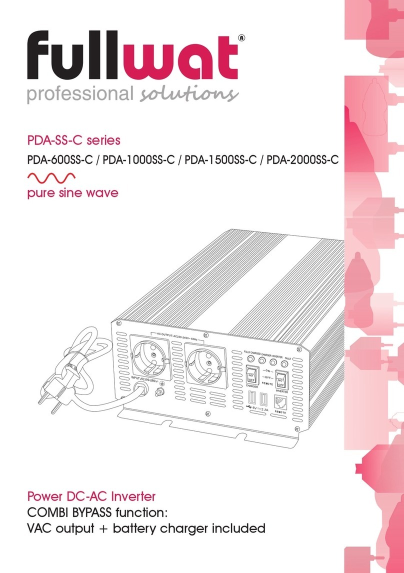
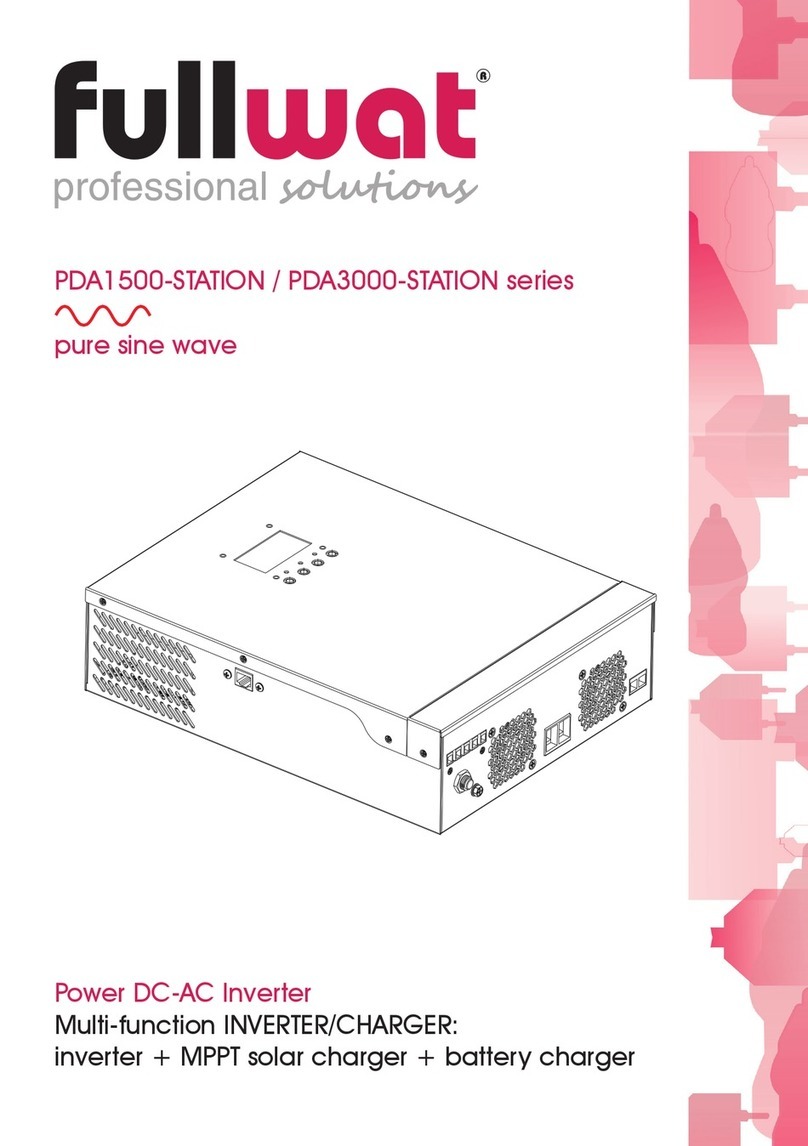
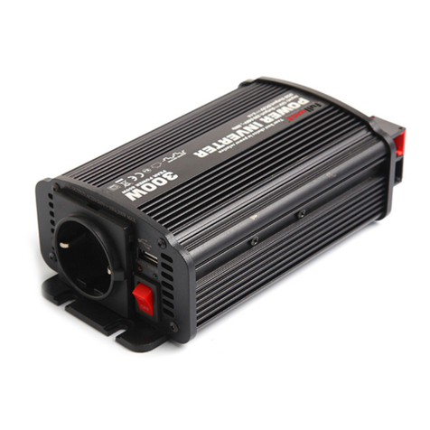
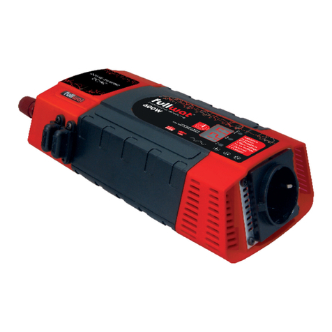
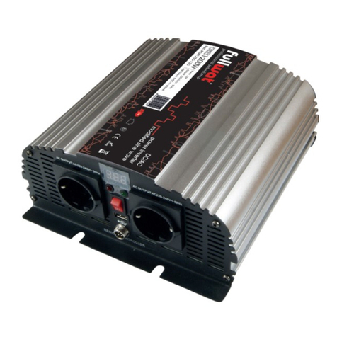
Fullwat PDATROLY-1000 User manual

PDATROLY-1000
Mobile DC to AC power inverters with battery charger
User’s manual
Design Features
•Switch mode design.
•Compact design.
•Complete protection design.
•Inverter re-start function.
•3-stage charger design.
•Wide volt range operation.
•Durable and corrosion resistant construction.
•Transformer isolated for safety.
•By pass function.
•Emergency backup light (LED) function
•One more DC terminal to connect battery or solar panel
•Max. 100Ah battery space.
•With USB power port.
List of contents
1. Important safety instructions .........................................................................1
2. Where to install ..............................................................................................1
3. Batteries..........................................................................................................2
4. Charging time..................................................................................................3
5. Features ..........................................................................................................3
6. Specifications ..................................................................................................4
7. Battery charger ...............................................................................................5
8. Troubleshooting guide....................................................................................7
9. Warranty.........................................................................................................7

1. Important safety instructions
WARNING
Before you install and use your inverter, be sure to read
and save these safety instructions
General safety precautions
Do not expose the inverter to rain, snow, spray, bilge or dust. To reduce risk of hazards, do not
cover or obstruct the ventilation openings. Do not install the inverter in a zero-clearance
compartment. Overheating may result.
To avoid a risk of fire and electric shock make sure that existing wiring is in good electrical
conditions and the wire size isn’t undersized. Do not operate the inverter with damage or
substandard wiring.
This equipment is not ignition protected and employs components that tend to produce arcs
or sparks. To reduce the risk of fire or explosions, do not install in compartments containing
batteries or flammable materials or areas in which ignition protected equipment is required.
Never smoke or allow a spark or flame in vicinity of battery or engine.
Not installing a fuse can result in fire that may cause injuries and/or damages.
You may observe a spark when making the cable connections since current may flow and
charge capacitors in the inverter. This is normal. Do not make cable connections in the
presence of flammable fumes; it may result in explosion and/or fire.
Shock Hazard. Before proceeding further, carefully check the inverter is not connected to any
batteries, and that all wiring is disconnect from any electrical sources. Do not connect the
output terminals of the inverter to an incoming AC source.
Risk of electrical shock. Do not remove cover, no user serviceable parts inside. Refer servicing
to qualified service personnel.
2. Where to install
Your inverter should be installed in a location that meets the following requirements:
Dry: keep the inverter away from any water or moisture.
Cool: Ambient air temperature should be between 0ºC y 40ºC (32ºF and 104ºF)
Ventilated: Ensure that the unit is located in a well ventilated compartment. At least 15cm (6
inches) of clearance are required around the inverter for air flow. Verify that all ventilation
openings on the unit (front and rear panels) are not obstructed.
User’s manual - 1 - PDATROLY-1000

Installation diagram:
Don't reverse the (+) and (-) of the battery, or internal damage will cause.
''Damage caused by reversed polarity is not covered by the warranty.''
3. Batteries
To achieve 50% cycling you should calculate your amp-hour consumption between charging
cycles and use a battery bank with twice that capoacity. To calculate Amp-hour consumption,
fisrt look at the rating plate on your AC appliance or tools.
Each appliance or toll will be rated in either AC amps or AC watt or AC VA(volt-amperes)
apparent power.
Use one of the following to calculate the DC amp-hour draw for a 12V system.
(AC amps x 19.1 if mains is 230VAC) x 1.1 x hours of operation = DC amp-hours.
(AC watts/12) x 1.1 x hours of operation = DC amp-hours.
(AC VA/12) x 1.1 x hours of operation = DC amp-hours.
In all formulas, 1.1 is the factor for inverter/charger efficiency.
Calculate the above for every AC appliance or tool you intend to use on your inverter. This will
give you the total number of amp-hours used between recharges. Size your battery bank using
this number as a guideline. A good rule to follow is to size the battery bank about two times
mlarger than your total amp-hour load requirement. Plan on recharging when 50% discharged.
Many electrical motors have momentary starting requirements weel above their operational
rating. Start up watts are listed where appropiate. Individual styles and brands of appliance
may vary.
NOTICE:
The output of this device is not pure sine wave, but modified sine wave
(1) Small Load Inverter LED Indicator : Green.
(2) Half Load Inverter LED Indicator : Orange.
(3) Full Load Inverter LED Indicator : Red.
User’s manual - 2 - PDATROLY-1000
Battery
+
-
Velcro belt to fix the battery
Connect to battery ( + : red /
-
: black)

4. Charging time
Formula: Charging time will depend on the capacity oy your battery and on how deeply is
discharged. The following equation calculates an approximate charging time:
Charging time =
CAP x DOD
CC x 80%
Where:
Charging time: battery recharge time in hours.
CAP: Battery capacity in ampere-hours
DOD: Battery depth of discharge in per cent. A fully discharged battery has a 100%
DOD.
CC: Charge current, the rated current output of the charger in amperes
80%: Typical charging efficiency fo lead-acid batteries.
Example: A group size battery rated at 100 amp-hours is 40% discarged, that is it has a
DOD = 40. Carging time with the charger of a PDATROLY-1000 is calculated as
follows:
Charging time =
100Ah x 40%
= 5 hours
10A x 80%
5. Features
(1) A Movable power system --- Modified sine wave inverter with 3-stage 10A battery
charger.
(2) Switch mode design.
(3) Compact and dexterous dimension design.
(4) Complete protection design --- overload, overtemp, short circuit, high/low volt ... etc.
(5) Inverter re-start function.
(6) 3-stage charger design --- bulk, absorption, float.
(7) Wide volt range operation (180~265V)
(8) Durable and corrosion resistant construction.
(9) Transformer isolated for safety.
(10) By pass function.
(11) Emergency backup light (LED) function.
(12) One more DC terminal to connect battery or solar panel (Solar charger controller as
intermediary suggested).
(13) Max. 100Ah battery space.
(14) With USB power port.
User’s manual - 3 - PDATROLY-1000

6. Specifications
Model PDATROLY-1000
INVERTER
DC input voltage 12VDC
DC input voltage range
10~16VDC
Surge power 2000W
Continuous power 1000W
Wave form Modified sine wave
AC output voltage 230VAC
User’s manual - 4 - PDATROLY-1000
(Front view)
Inverter ON
Charger
AC IN
USB Port
Battery Volt
&
Charger Step
14V
13V
12V
11V
10V(Fault)
Charger Step
40% graph flashBulk:
Absorption: 60% graph flash
Flat: 100% graph flash
Fault (red):
No battery, low input volt,
charger overtemp..
(Side view)
1
1
2
2
1. DC Terminal
2. Thermal cooling fan
3. ON/OFF Switch
4. Inverter Indicator
5. Breaker
6.
7. Inverter / AC Output
Receptacle
- With AC IN power
- OFF
- With Battery Power
( AC Power is failed )
Light Switch
1. Emergecy Light
2.
6 7
345
. Charge AC Input Port

Frequency 50Hz ± 3%
AC regulation ± 8%
No load current draw 0.6A
Battery low alarm 10.5 ± 0.5VDC
Battery low shutdown 10 ± 0.5VDC
Overvoltage 16 ± 0.5VDC
Battery polarity reverse Fuse burn out
Overload Re-start 2 times, shutdown if failed
By-pass function Yes
CHARGER
Output current 10A
AC input voltage 180~265VAC
Charging type 3 stage
Bulk stage 14.5 ± 0.5VDC, 10A
Absortion stage 14.5 ± 0.5VDC, 10~1A
Float stage 13.6 ± 0.5VDC, minimum 0.5A
Frequency 45~65Hz
Recommended battery type Lead acid
Recommended battery size 40~160Ah
DC power supply (fixed output) mode 12.5VDC
PROTECTION
Overload protection Yes
Overtemperature protection Yes
Inverter output reverse protection Fuse blow
Charger output reverse protection Fuse blow
Inverter short-circuit protection Shut-off
Overtemperature 55 ± 5ºC
Dimension (LxWxH) 455 x 390 x 340
Net weight 9.5Kg (without battery)
Gross weight 10.5Kg (without battery)
Specifications subject to change without notice
7. Battery charger
For lead-acid and lead-calcium, lithium-iron batteries only.
Stage 1: Bulk Charge Max 14.5±0.5V, 10A. Charger LED Indicator: Red.
Stage 2: Absorption Charge 14.5±0.5V, 10~1A. Charger LED Indicator: Red.
Stage 3: Float Charge 13.6±0.5V, min. 0.5A. Charger LED Indicator: Orange.
Complete charging, charger LED Indicator: Green.
User’s manual - 5 - PDATROLY-1000

Status LED:
Inverter Mode
Inverter LED Alarm Question Solution
Orange flash 3 short alarm -Overload
-Short circuit
-Reduce load
-Solve short circuit
Orange flash Long alarm -Low battery shut down
-Hightemp shut down
-Replace or charge the
battery
-Allow inverter/charger to
cool off. Improve
ventilation.
Green flash Quick alarm
-Low battery
-Poor DC wiring
-Poor DC terminal connection.
-Charge or change battery
-Improve DC wiring
-Improve DC terminal
connection
No Inverter LED None High battery shut down Reduce input volt
Charger Mode
Charger LED Alarm Question Solution
Red flash,
(output 2-3A only) None Hightemp Allow device to cool off.
Improve ventilation.
User’s manual - 6 - PDATROLY-1000
3-Stage Battery Charger
DC Voltage
DC Current
Charging started Bulk stage
Constant current
at maximum
charge rate
Absorption stage
Constant voltage
at Absorption
voltage setting
Float stage
Constant voltage
at the Float
voltage setting
Load current on demand
Charger LED
indicator Red Red Orange
Time
:

8. Troubleshooting guide
Problem Things to check
No invertir output
1. Battery voltage under load
2. Battery connections and DC fuse
3. Circuit breaker on front panel
4. Thermal condition, high powered loads or inadequate
ventilation may cause overheating
5. Overloads or chort circuit, check for excessive loads or
bad wiring connections
Low inverter output voltage
Confirm that your volt meter is a true RMS meter.
Standard volt meters will no accurately read the waveform odf
the inverter.
If a true RMS meter is not available, check the brightness of an
incandescen light bulb. If it appears normal, the output voltage
is properly regulated.
Little or no output from
battery charger
1. Wiring connections-check both the AC and DC
connections.
2. AC input voltage-low voltage input will result in low DC
output current.
3. AC input spec. isn't correct to Inverter/Charger spec.
V2 01/2013
9. Warranty
We offer 12 months warranty from the date of purchase, as stated in invoice or purchasing
proof, and will repair or replace any defective power invertir.
This limited warranty is void if the unit is abused, modified, installed improperly, if the housing
has been removed, if the serial number is missing, or if the original identification markings
have been defaced, altered, or removed
The supplier is not liable for any incidental, consequential or other damages arising from the
use, cost of removal, installation, or troubleshooting of the customer's electrical systems.
Repair or replacement are your sole remedies and shall not be liable for damages, whether
direct, incidental, special or consequential, even though cause by negligence or other fault.
This is only warranty and the company makes no other warranties, express or implied,
including warranties of merchantability and fitness for a particular purpose.
User’s manual - 7 - PDATROLY-1000
Table of contents
Other Fullwat Inverter manuals

Fullwat
Fullwat PDA300-LC Series User manual

Fullwat
Fullwat PDA-D Series User manual

Fullwat
Fullwat PDA500SS User manual

Fullwat
Fullwat PDA-SS-C Series User manual

Fullwat
Fullwat PDA1500-STATION Series User manual

Fullwat
Fullwat PDA300S User manual

Fullwat
Fullwat PDA5500-STATION User manual

Fullwat
Fullwat PDA400 User manual
Popular Inverter manuals by other brands

KEHUA TECH
KEHUA TECH SPI-B2S Series user manual

Miller
Miller Invision 352 MPa Auto-Line CE Technical manual

Nidec
Nidec Leroy-Somer POWERDRIVE MD2CS installation guide

Briggs & Stratton
Briggs & Stratton 40204 Operator's manual

SolaX Power
SolaX Power X3-Fit-8.0-E Quick installation guide

GE
GE HOME NERATOR SYSTEM 18000 WATT Installation and start-up manual