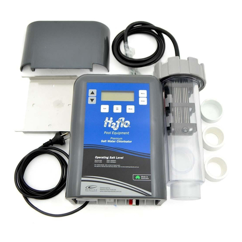
Pool Systems G2flo ZEN User manual


SPECIFICATION
Model No C-H2FZ20 C-H2FZ30 C-H2FZ40
Voltage Input 240V AC 240V AC 240V AC
Amps Input 8.6A 9.0A 9.1A
Frequency 50 50 50
Voltage output 8V DC 8V DC 8V DC
Amps Output 9.5A 14A 18.5A
Chlorine Production 20gr/hr 30gr/hr 40gr/hr
Weight 8.5kg 8.7kg 8.9kg
Dimensions 27cm H 27cm H 27cm H
20cm W 20cm W 20cm W
17cm D 17cm D 17cm D
Pump Outlet Rating for all model sizes 240V @ 8amps MAX
!
"!
!"#"$%$&"'
'
'
#( ")*+',--.*,/01'0,/'21'3+14'25'0)*.461/',714'869:';'51,6+',/4',29<1',/4'-16+9/+'
=*>)'6143014'-)5+*0,.?'+1/+965'96':1/>,.'0,-,2*.*>*1+'96'.,0@'98'1A-16*1/01',/4'
@/9=.1471'*8'>)15'),<1'211/'7*<1/'+3-16<*+*9/'96'*/+>630>*9/'09/016/*/7'3+1'98'
,--.*,/01'*/','+,81'=,5',/4'3/416+>,/4'>)1'),B,64+'*/<9.<14('C)*.461/'+),..'/9>'-.,5'
=*>)'>)1',--.*,/01('C.1,/*/7',/4':,*/>1/,/01'+),..'/9>'21':,41'25'0)*.461/'=*>)93>'
+3-16<*+*9/('
'
'
D( ")1',--.*,/01':3+>'21'-16:,/1/>.5'09//10>14'>9'8*A14'=*6*/7',00964*/7'>9'>)1'
/,>*9/,.'=*6*/7'63.1+('")1',--.*,/01':3+>'21'*/+>,..14?':,*/>,*/14',/4'+16<*014'25','
E3,.*8*14'.*01/+14'1.10>6*0*,/('$E3*-9>1/>*,.'29/4*/7':3+>'21'0,66*14'93>('
'
'
'
C( %1,/+'98'4*+09//10>*9/'869:'>)1'+3--.5':,*/+'),<*/7','09/>,0>'+1-,6,>*9/'*/',..'
-9.1+'>),>'-69<*41'83..'4*+09//10>*9/'3/416'9<16<9.>,71'0,>17965'FFF'09/4*>*9/+':3+>'
21'*/096-96,>14'*/'>)1'8*A14'=*6*/7'*/',00964,/01'=*>)'>)1'=*6*/7'63.1+('
'
'
G( ")1',--.*,/01'+)93.4'21'+3--.*14'>)6937)','61+*43,.'03661/>'41<*01'HCG'),<*/7','
6,>14'61+*43,.'9-16,>*/7'03661/>'/9>'1A0114*/7'IJ:,('
'
'
'
$( K,6>+'09/>,*/*/7'.*<1'-,6>+?'1A01->'-,6>+'+3--.*14'=*>)'+,81>5'1A>6,L.9='<9.>,71'/9>'
1A0114*/7'MNO?':3+>'21'*/,001++*2.1'>9','-16+9/?'*/'>)1'2,>)'96'+-,('
'
'
P( K,6>+'*/096-96,>*/7'1.10>6*0,.'09:-9/1/>+?'1A01->'61:9>1'09/>69.'41<*01+?':3+>'21'
.90,>14'96'8*A14'+9'>),>'>)15'0,//9>'8,..'*/>9'>)1'2,>)'96'+-,('
'
'
Q( F8'>)1'+3--.5'0964'*+'4,:,714?'*>':3+>'21'61-.,014'25'>)1':,/38,0>3616?'*>+'+16<*01'
,71/>'96'+*:*.,6.5'E3,.*8*14'-16+9/'*/'96416'>9',<9*4','),B,64('
!
! !

INDEX
3. INDEX & SPECIFICATION
4. INSTALLATION
5. PLUMBING
6. TIMER
7. OPERATION
8. WATER QUALITY
9. TROUBLESHOOTING
10. PARTS
11. WARRANTY
3.
SPECIFICATION
Model No C-H2FZ20 C-H2FZ30 C-H2FZ40
Voltage Input 240V AC 240V AC 240V AC
Amps Input 8.6A 9.0A 9.1A
Frequency 50 50 50
Voltage output 8V DC 8V DC 8V DC
Amps Output 9.5A 14A 18.5A
Chlorine Production 20gr/hr 30gr/hr 40gr/hr
Weight 8.5kg 8.7kg 8.9kg
Dimensions 27cm H 27cm H 27cm H
20cm W 20cm W 20cm W
17cm D 17cm D 17cm D
Pump Outlet Rating for all model sizes 240V @ 8amps MAX

Position the chlorinator power module at least 1m above ground and at least 2m from the
pool edge.
Mount the stainless steel bracket to a solid structure with the screws provided and fit the
power module over the two raised pins on the bracket, secure with the 2 locking clips
provided.
Protect the chlorinator module and cell housing from direct sunlight and rain where
possible for extended life.
Connect the mains plug from the chlorinator power pack into a RCD Protected 240V
mains 10A outlet.
Remove the WHITE J-Box Cover at the bottom of the Power module and connect the cell
cable, RED to RED, BLACK to BLACK, WHITE to WHITE.
Connect the mains plug from the pump into the pump outlet on the bottom of the
chlorinator power pack.
INSTALLATION
4.

Optional
Return
To Pool
Using
Outlet
1 or 2
PLUMBING
Plumbing should be performed by a qualified Plumber or a pool service technician
where possible.
WARNING: Do Not apply Priming Fluid
to the Clear Cell Housing
All pipe work should be primed with priming fluid before glue is applied, any high pressure
PVC glue will work, make sure both surfaces are well coated before mating the connections
as you will only have a few seconds before the glue bond will take.
Piping from the filter to the Cell should enter the pipe connection closest to the cell head as
per the image below as this is where the water sense probe has been installed during
manufacture. NOTE: When plumbed from the other direction and used with variable speed
pumps having very low flow rates the water probe may not get covered with water causing
the chlorinator to display Priming Cell.
5.

TIMER
Setting the Time
Remove the clear cover from the timer
To adjust the timer to correct time of day, turn the timer in a Clockwise direction,
the Hour & Minute hands will start to move.
The illustration below shows the Time of day set to 4.30pm indicated by the arrow
( 6 = 6am, 12 = Midday, 18 = 6pm, 24 = Midnight etc )
Setting Operating Times
There are 96 levers around the face of the Timer, each lever will operate the chlorinator
for 15 minutes, the illustration below shows operating times set for 6 - 10am and 4 - 8pm
6.

OPERATION
Chlorine Control
The Control Knob on the front of the chlorinator is used for chlorine control, Fully anti-clockwise
is 0% and fully clockwise is 100%. There are 10 LED segments to indicate percentage production,
every LED segment = 10% chlorine production
Manual Operation
To manually operate the Chlorinator & Pump move the RED tab on the timer
to the upper position
Automatic Operation
To Automatically operate the Chlorinator & Pump from the Timer settings
move the RED tab on the timer to the middle position
Turn OFF
To turn the Chlorinator & Pump OFF move the RED tab on the timer
to the lower position
The illustration below shows the chlorinator set for Automatic operation
and chlorine production @ 50%
WATER QUALITY
Your water BALANCE should be kept within the following levels for trouble free operation
SALT - Sodium, Mineral or Magnesium
Measurement Interval - once a month
4000 mg/L
pH
Measurement Interval - once a week
7.2 - 7.8 Controlling your pH is most important so that you have good active levels of
chlorine throughout the water, high pH above 8.0 will reduce the effectiveness of chlorine
When pH is high, Adding Hydrochloric acid will lower the pH
When pH is low, Adding Sodium bicarbonate will raise the pH
Stabiliser
Measurement Interval - Every 4 - 6 weeks
Stabiliser level should be kept between 30-70 mg/L, levels higher than this aren’t required.
Stabiliser should be measured by your pool shop every 4-6 weeks but most importantly in
summer when UV levels are highest
Chlorine
Measurement Interval - once a week
Chlorine ( Free Chlorine ) should be measured once weekly and kept between 2 - 3 mg/L for
effective disinfection, adjust the chlorinator output percentage or the pump run time to
either increase or decrease this level as required
Total Alkalinity
Measurement Interval - 4 -6 weeks
80 - 150mg/L
Calcium Hardness
Measurement Interval - every 3 months
175 - 300mg/L
7.

WATER QUALITY
Your water BALANCE should be kept within the following levels for trouble free operation
SALT - Sodium, Mineral or Magnesium
Measurement Interval - once a month
4000 mg/L
pH
Measurement Interval - once a week
7.2 - 7.8 Controlling your pH is most important so that you have good active levels of
chlorine throughout the water, high pH above 8.0 will reduce the effectiveness of chlorine
When pH is high, Adding Hydrochloric acid will lower the pH
When pH is low, Adding Sodium bicarbonate will raise the pH
Stabiliser
Measurement Interval - Every 4 - 6 weeks
Stabiliser level should be kept between 30-70 mg/L, levels higher than this aren’t required.
Stabiliser should be measured by your pool shop every 4-6 weeks but most importantly in
summer when UV levels are highest
Chlorine
Measurement Interval - once a week
Chlorine ( Free Chlorine ) should be measured once weekly and kept between 2 - 3 mg/L for
effective disinfection, adjust the chlorinator output percentage or the pump run time to
either increase or decrease this level as required
Total Alkalinity
Measurement Interval - 4 -6 weeks
80 - 150mg/L
Calcium Hardness
Measurement Interval - every 3 months
175 - 300mg/L
8.

TROUBLESHOOTING
Before troubleshooting, remove power from the chlorinator by turning off at the wall or
removing the mains plug, wait for 10 seconds then re-apply power, this will reset the
internal processor to its default state.
9.
Lights are scrolling 0 - 100%
PROBLEM CAUSE REMEDY
Chlorine output will not
reach 100%
Salt level not high
enough
Salt level should be
4000mg/L
Water temp is low Winter water temps
will reduce output
Cell has too much calcium
deposit on plates
Clean the cell with
cleaning solution or
high pressure hose
Cell could be at end of life If salt level is correct,
water temp is high and
cell is clean you may
require a new cell
No chlorine measured in the
water
Not enough Stabiliser
in the water
Add Stabiliser until you have
30 - 70mg/L
Chlorinator isn’t operating
long enough or at high
enough output
Dirty cell
Increase operating hours or
percentage output
Clean the cell with
cleaning solution or
high pressure hose
Priming cell
No water is flowing through
the cell
Make sure water is flowing
through the cell, pump
may not be operating
Lights are Flashing Lights will flash when the
chlorinator is turned ON
No action required
Lights are Flashing and
output will only acheive
70%
Auto power reduction due
to High salt condition
5000mg/L or above
Reduce salt level
to 4000mg/L
Lights will flash when you
have a high salt condition
Reduce salt level
to 4000mg/L
Pump is always ON The pump may have been
connected to the mains
before the chlorinator
Make sure the pump is
plugged into the 240V
socket on the chlorinator
Tab on the TIMER has
been set to the wrong
position
See page 7 for instruction

Plastic Cover
Mounting Bracket
Backing Plate
20-30-40gr Transformer
Pump Outlet
Main PCB
Ribbon Cable
J-Box
Timer
Control PCB
Control Label
Control Knob
Mains Cable
Part No Description
1. Mounting Bracket
2. Backing Plate
3. 20 - 30 -40gr Transformer
4. Pump Outlet
5. Timer
6. Clear Window
7. Control Knob
8. Control PCB
9. Plastic Cover
10. J-Box
11. Mains Cable
12. Ribbon Cable
13. Main PCB
14. Control Label
Clear Window
PARTS
10.

11.
WARRANTY
• Ho Clorinators are not available for sale on the internet, therefore any purchase on the internet
automatically voids the stated warranty.
• Ho Chlorinators must be installed by a qualied person (pool retailer, pool service person or pool builder)
otherwise warranty claims will be void.
• Before contacting Ho Chlorinators for warranty issue, please check the troubleshooting guide on page 9.
• The majority of issues can be resolved while the unit remains in position. Please don’t remove the unit unless
you have already rung the Ho Chlorinator help line on 0429 295 746.
• In very limited situations, you may be advised to return the unit or parts of the unit. This should only be done
with the express approval in advance from Ho Chlorinators on 0429 295 746.
• Your Ho Chlorinator carries the following warranty should a fault occur due to faulty materials or
manufacture.
• POOL SYSTEMS warrants the original purchaser of the control panel and cell electrode, whether personal or
commercial use, for a period of (see warranty period below), from the date of purchase should the purchaser
disclose that this particular equipment failed due to faulty materials or manufacture.
• The equipment under warranty claim must be returned to Ho Chlorinators for repair or replacement.
• The warranty does not apply to any material supplied or workmanship performed by others in the process
of installing the equipment. Nor does it apply if the equipment has been repaired or altered by anyone
other than Ho Chlorinators personnel or POOL SYSTEMS Representative. This warranty does not apply
if the equipment has been subject to misuse or misapplication.
• The warranty applies to materials and manufacture only. This warranty does not cover an act of God,
i.e. storm and tempest, lightning strike, oods, tsunami, earthquake etc.
• POOL SYSTEMS or its agent will replace at no charge, all parts, which show faulty materials or manufacture
faults. The foregoing constitutes the entire liability of POOL SYSTEMS to the original owner of the equipment.
• There are no other warranties, expressed or implied, including but not limitied to the implied warranties
of merchantability or tness for a particular purpose other than those contained herein.
• In no event will POOL SYSTEMS PTY LTD be liable to the original or subsequent owners either directly
or as an indemnitor, or any direct, incidental or consequential loss, damage or economic loss, damage
or injury to any person or property arising out of or relating to the equipment or any parts supplied
in the equipment, except as expressly stated herein.
• No other person, or company or organisation is authorised to make any warranties, guarantees or
representations, or allowed to allow any exceptions to the warranty, or assume any other liability
or obligation on behalf of POOL SYSTEMS PTY LTD in connection with the equipment. This warranty
shall not extend to any expenditure incurred.
Warranty Period
Domestic Power Pack 3Years
Cell Electrode
Commercial Power Pack 3Years
Cell Electrode
www.poolsystems.com.au
3Years
1Year
Our goods come with guarantees that cannot be excluded under the Australian Consumer Law. You are
entitled to a replacement or refund for a major failure and compensation for any other reasonably
foreseeable loss or damage. You are also entitled to have the goods repaired or replaced if the goods fail to
be of acceptable quality and the failure does not amount to a major failure.

Table of contents
Other Pool Systems Swimming Pool Filter manuals
Popular Swimming Pool Filter manuals by other brands

afm marine
afm marine PSK-SK5.0 User instructions

BIO-LAB CANADA
BIO-LAB CANADA Mineral Springs Pool Pilot Soft Touch 48 Installation and operation manual

Procopi
Procopi pH 220 Installation and operating instructions

Gemas
Gemas PURITRON GSC 10 instruction manual

Bestway
Bestway FLOWCLEAR 58634 owner's manual

Pentair Pool Products
Pentair Pool Products Tagelus datasheet