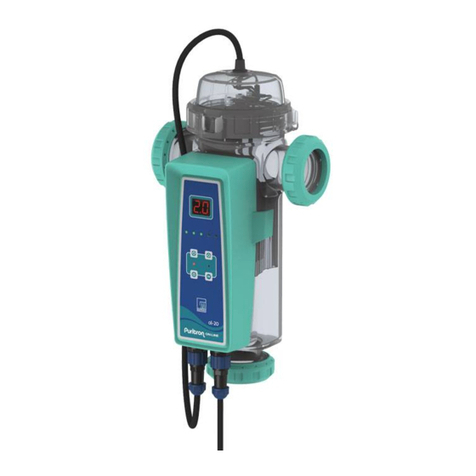
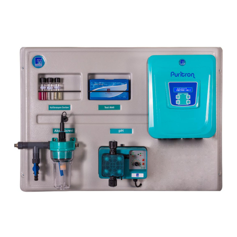
Gemas PURITRON GSC 10 User manual

GEMAS pH CONTROLLED
PURITRON
SALT WATER CHLORINATOR
INSTRUCTION MANUAL
1. Introduction
2. Salt Water Chlorinator Description
3. Installation
4. Water Preparation
5. Salt Addition
6. Operating
7. Recommendations
8. Technical Characteristics
9. Warranty, After-Sales Service and Spare Parts

1- Introduction
We thankfull for your trust in us with your purchase of a GEMAŞ
Puritron Salt-Water Chlorinator. GSC chlorinators are manufactured
following the strictest quality controls and using the most advanced
technology regarding saltwater electrolysis. In addtion the R&D process
was completed in may 2017 and pH measurement and dosing was added
to the product.
With minimum maintenance and following elementary rules for
installation and use, you will enjoy an extremely efficient device for many
years.
Please read this manual carefully before its installation or start-up,
keeping it for further reference.
The sections concerning installation require certain technical knowledge
on the swimming pool. We advise you seek the aid of a professional.
Please pay special attention to the points marked with the symbol: .
Any damage caused to the chlorinator resulting from not complying with
these precautions may lead to cancellation of the guarantee.
Any damage caused to the chlorinator resulting from unapproved
executions except for the warnings may lead to out of warranty cover.
2- Salt Water Chlorinator Description
You will find the following elements in your GSC Device package:
Power supply and control unit
a. LCD screen
b. Control Keys
c. DC cell cable
220 VAC power supply cable
Electrolytic cell (For chlorine production)
Electrolytic cell (For pH measurement)
Chlorine flow cell plug
pH electrode
pH 4,0 and pH 7,0 calibration liquid
Cell Housing
Thread (Compatible with Ø63mm Fitvalf Valve Handle)
2 pieces 8 mm, 20 mm threaded adapter connected to record

4 pieces 8 dowel and 4 pieces 5x40 wood screw
1 piece pH dosage pump electrical output socket
O’ring seal
Wall Bracket
PH Probe
3- Installation
Control Unit
Attach the control unit, using the brackets(7) in the back and the screws supplied, in a position
providing easy access and reading. The control(1) unit will be placed at a maximum of 1.5 metres
away from the electrolytic cell. Choose a place with good ventilation and protected from the rain and
possible water leaks.
Connect the ground wire (yellow and green) of the 220 VAC power supply cable(2) to ground in the
swimming pool switchboard. Connect phase (brown) and neutral (blue) to the output of the pump
contactors in such a way that the chlorinator is powered only when the pump is working. Connect the
chlorinator to free terminals. Do not use terminals occupied by the wires of the pump. This will avoid
the chlorinator to be electrically connected to the pump after switching off the current, which could
cause serious damage.
The chlorinator should be powered with 220 VAC and only when the pump is connected and
the water is circulating through the cell. Please pay special attention if your installation is
threephase (pump at 380 VAC).
Cell housing (4)
The cell housing(4) will be installed in the return flow to the swimming pool and will be always after
the last elements (filter, heater, etc) the water goes through. Use glue for rigid PVC and wait for it to
dry completely before inserting the cell.
A by-pass installation with three valves will always be recommended. This layout allows
the amount of water circulating in the cell to be adjusted and the swimming pool to work
with the housing disassembled. At a pump with certain power, the by-pass is necessary to
reduce the speed of water at its passage through the housing and to avoid damaging
vibrations in the electrodes.
It can be used vertically or horizontally but we recommend vertical position . Vertical
position allows for emptying the cell without water spills and provide enoung space to
unscrew the thread and extract the cell once the housing has been installed. There is no
recommendation of water flow.
If the cell is installed at a height below that of the output filter, the
gases created in the housing, resulting from the electrolysis and could
damage the filtration elements. Please see below diagram for avoid this
circumstance.
220 V electrical
connection
pH electrode
connection
Dosage pump
electrical
socket
connection

Cell
The cell (3) needs to be in the housing making sure that the open outer zone
coincides with the water inlet tube. Make sure the o’ring(6) is in its place and not
to leak. Afterwards, connect the DC cable to the cell terminals.
NOTE: The cell connector is designed to ensure optimum electrical contact with
the cell terminals and pressing slightly may be required for its placement. Before
connecting this, please make sure the smallest orifice is aligned with the
corresponding terminal.
If you use a sand filter, open it and add 2 to 3 cm of sand above the upper
pipe.
The hose of the Ph dosing pump should be installed in the system in such a way
that the water does not contact other equipment.
pH Flow Cell
The Ph reducer injection should be after the electrolysis cell.
Otherwise, cell electrics will interfere with the acid and will be damaged
by corrosion and will be out of warranty. Do not locate acid tanks where
there is insufficient flow. Otherwise, electronic components can be
exposed to corrosion due to acid effect. The location of the flow cell
should be before the chlorine cell, otherwise high-density chlorine can
damage the flow cell and cause the product to go out of warranty.
After measure water pH, measured water is injected
to return line with a clamp settle.
Suction Collector
The sample is taken from the
water and sent to the pH flow
cell for measurement and
returned to the system.
The water from the suction
collector is connected to
the flow cell for
measurement.

4- Water Preparation
Preferably use water from the urban network. If the water is sourced with a
different resource, please analysed it and make sure there is no adverse factors
such as a high concentration of metals or calcium for working of the system . Also
check the water complies with the health standards.
Adjust the water before starting your chlorinator and add 1 Kg of chlorine
stabiliser for each 25 m3 of water (20 to 30 ppm) (or according to the indications
by the manufacturer)
Note: The stabiliser prevents the desintegration of chlorine due to UV. The
absence of the stabiliser will force it to produce more chlorine, thus reducing the
lifetime of the cell. On the other hand, too much stabiliser has an adverse affect
on the desinfecting characteristic of chlorine.
The pool water needs to be presenting the below parameters:
Salt 5-6 kg/m3
TAC 60 –100 ppm
TH 15-200French
Stabiliser 20-30 ppm (or according to the indications by the manufacturer)
Temperature > 100C
5. Salt Addition
During this process, the system needs to be totally closed through the salt dissolves
completely. The operating of the chlorinator with undissolved salt would irreversibly
damage the cell. The damage is occured by this reason cause to cancellation of the
guarantee.
Calculate the volume of the swimming pool and add 5 to 6 Kg of salt per cubic metre.
Make sure the chlorinator is disconnected and do not operate the filtration system at least
24 hours.
Wait for four weeks before adding salt into a recently coating pool.
The hose from the pH
chemical tank is
connected to the lower
hose connection of the
dosing pump.
The upper hose connection of
the dosing pump is the
connection to the pool. After
this, the chemical is given to the
pool water.
At the end of the hose discharge
line carrying the chemical from
the dosing pump, the water
should be added with a clamp
from a point where it will not
come into contact with any
equipment after that point. If
water containing dense
chemicals comes in contact
with any equipment, it may
cause irreversibly damages.

The salt dissolving process can be accelerated using the pool cleaner. Check the salt
concentration is between 5 and 6kg/m3 using a measurement kit of any pool shop.
The operating of the chlorinator implies no salt consumption. However, the salt
concentration may be reduced with the passage of time due to rain or other freshwater
contributions. Whenever the salt needs to be added, pour the salt as near as possible to
the return lines. Strictly recommended, do not pour the salt in the skimmers or the drain
inlet.
6. Operating
The above screen appears when the salt chlorine generator is switched off. To switch on or off the
chlorinator, press the MENU ON / OFF. For reach the setup menu press the same button for 3
seconds.
This display indicates the production level (CL = 100%), the measured pH, the availablity of the
production of the existing salt level and the direction of polarization at the bottom left arrow. If the
arrow indicating the polarization direction is moving, chlorine is produced, but if the arrow does not
move, the chlorine production is stopped. The A mark on the display indicates that the dosing pump is
in automatic mode, and the drop mark indicates that the dosing pump is running. Using the arrows
on the main screen, a chlorine production rate of 0% (chlorine production stopped) to 100% (full
efficiency) is selected as needed.
For back to the other setups pres the MENU button.
You need to make the setting according to your pool depending on the different conditions (number
of swimmers, temperature, etc.). In general, we recommend setting the minimum production
percentage that produces a crystal clear water in your pool.
Polarity Change Period
The polarity applied to the cell is periodically reversed to dislodge accumulations of lime. This period
is determined 8 hours by the manufacturer. Depending on the condition of your pool it may be
necessary to reduce this period up to 1 hour to increase the frequency of cleaning. The longer this
period is, the longer the electrode cell duration will be. A period of less than 4 hours will reduce the
length of the electrode. We recommend, therefore, to set this to the larger number of hours as
possible while you don’t see limescale on the cell.
When you enter the menu, press the OK key on the screen shown above and then use the OK button
to set the desired time with the arrows on the following screen.

When a pole is changed, it switches to standby mode for 10 minutes and the screen shown
below is displayed (the hourglass).
pH Settings
Use the arrows on the menu to select "PH SETTINGS" and press "OK" button.
1- pH Mode Setup
The pH option menu is the first option to oppose pH mode. This option is the menu
associated with the operation of the dosing pump. When you enter the PH mode menu,
the settings shown below and the definitions given below are made.
PH OFF: Turn off the PH dosage pump.
PH ON: Turn on the dosing pump until the PH dosing pump is switched to the automatic or
off position via the menu.
Warning: It is recommended that this mode be used only when the dosing pump’s air
evacuated.

PH Auto: Measuring the pH dosing pump according to the supplied pH meter and adjusting
the stopping value according to the measurement.
PH SET: The menu for making the pH settings of the pool water is from the PH SET
submenu on the PH SETTINGS menu.
PH SET: After pressing the OK button on the PH SET submenu, the desired pH value is
reached with the arrows and the adjustment is made by pressing the OK button again. The
factory setting is 7.00 and the recommendation value is 7.20.
PH TOL. : The level of the pool water pH value is used to adjust the operation of the dosing
pump after the value set in this menu is reached.
For example, in a salt chlorine generator set to PH SET value 7.0, if the pH TOL value is set
to 00,10, the salt chlorine generator will run when the pH dosing pump reaches pH 7,10.
This tolerance value is set using the arrow keys and the OK key.
PH BUF.SEC : This menu selects whether the dosing pump is connected to a pH-increaser
or pH-reducer chemistry. In this case, the pH-increasing chemistry-dependent dosing
pump is prevented from further increasing the already high pH.
ATTENTION : IT’S IMPORTANT THAT THE CHEMICAL AND THE SELECTION OF THE
DOSAGE PUMP.
IF THE PH REDUCER IS CONNECTED, THE ABOVE OPTION SHOULD BE SELECTED. IF THE PH
INCREASER OS CONNECTED, THE OPTION TO BE (+) IS A SUBMITTED (-) SIGN (+)
SELECTED.
PH CALIBRATION: For the pH calibration, press the OK key in this option and then proceed
as follows.

When the above text is displayed on the screen, put the electrode in the pH cell into the
pH 4 liquid supplied with the product and press the OK button.
PH electrodu, waits for 1 minute in pH 4 liquid and performs the same treatment for pH 7
liquid behind. If there is an imbalance in the section that says INITIAL PH, the product
automatically restarts the calibration.
The pH READ option allows the reading of the current pH value.
The language option allows you to change the menu language. Turkish language, English,
French, Spanish and Bulgarian languages are available.
Fault Message
This screen is displayed when the sensor detects no water and the control system stops
production. Check that there is water in the cell and that it goes to the top where the
probe is. Low levels can result from operating the chlorinator without the pump operating.
In this case turn off the device immediately. THE CHLORINATOR SHOULD NEVER BE
CONNECTED IF THE PUMP IS NOT WORKING OR THE WATER IS NOT FLOWING FREELY.
THE POWER SUPPLY OF THE CHLORINATOR SHOULD DEPEND ON THE PUMP’S POWER
SUPPLY.
A low water level in the cell may also be due to a dirty filter, an obstructed circuit or
insufficient pump power. As soon as the water level is restored the fault disappears.
This screen appears when the salt concentration in the water is too low to
prevent cell damage. Add enough salt (5 or 6 kg / m3 ideally) and when it is
completely dissolved press any button to reset the device. This screen can also
appear if the water temperature is too low or if there is a bad connection in the
cell cable.
Manuel Cell Cleaning
GSC chlorinator is provided with a self-cleaning polarity change system that
almost eliminates maintenance work. But, when the calcium concentration is very high,
this characteristic may not be enough to completely eliminate the lime residue. Visually
inspect the cell regularly to detect the presence of lime and, clean the cell if it’s necessary.
Ideally, you should let the cell dry completely during one or more days for the lime residue
to release themselves. You can help this by slightly hitting the cell. In this process please
be careful that do not harm the electrodes delicate cover. Do not use any metallic or
stabbing element to scratch the electrodes. You could also use water pression.
If you are able to remove the lime residue in this way, please proceed with the
below instructions.
1- Turn off the pump and the chlorinator
2- Disconnect the DC cable for the cell, unscrew the thread and extract the cell
3- If the pressurized water does not completely eliminate the calcium
deposits, submerge the cell in a 20% hydrochloric acid solution. Do not
submerge the cover of the cell where the terminals are. The hydrochloric
acid will react with the calcium producing gas.
4- Once clean, rinse the cell immediately with freshwater, dry the terminal area
properly and reinstall it in the housing.
Do not leave the cell in the acid solution for longer than 5 min. Do not
scratch the electrodes with metal objects. For safety reasons, always add
the acid into the water!
2- Recommendations
The bipolar cells of GSC Salt-Water chlorinator are manufactured using an
special technique with high quality standards, conferring them extraordinary
duration and resistance. However, there are several factors that may reduce the
best and longest performance of your chlorinator.
These are:
-Operating with lime residue on the surface of electrodes
-Excessive chlorine concentration (chlorine is corrosive above 3.0 ppm)
-pH too low or too high
-Absence or very high concentration of salt
-Water temperature below 10°C,
-Adding the salt when the chlorinator is working,
-pH corrector injection before the housing, in the skimmers or on the
bottom drain inlet
We recommend you periodically check the cell terminals and oiling them for
avoid sulphating.
Turn the equipment off whenever:
-No water circulates
-While cleaning the filter
-While the pool is being emptied
-The water is frozen
-While cleaning the cell
3- Technical Characteristics
Models
GSC 10
GSC 20
GSC 30
Maximum Flow
450 lt/min.
450 lt/min.
450 lt/min.
Maximum Pressure
320 kpa
320 kpa
320 kpa
Pressure Drop
5 kpa
5 kpa
5 kpa
Chlorine Production
10 gr/sa
20 gr/sa
30 gr/sa
Output Voltage
(Max.)
24 VDC
24 VDC
24 VDC
Current
2,5 A
3,7 A
5,0 A
Cell Type
Bipolar
Bipolar
Bipolar
Recommended
Salt Concentration
4-35 gr/l ppm
4-35 gr/l ppm
4-35 gr/l ppm
Cell Material
PMMA
PMMA
PMMA
Cell Lifetime
16.000 saat
16.000 saat
16.000 saat
Electrode Material
Titanium
Titanium
Titanium
Climate Type
Max. Pool Size
Max. Pool Size
Max. Pool Size
Temperate Climate
50 m3
100 m3
170 m3
Tropical Climate
35 m3
65 m3
110 m3
Power Supply
220 VAC
220 VAC
220 VAC
Consumption
100 Watt
190 Watt
300 Watt
Weight
3,0 kg
3,3 kg
3,5 kg
Warranty, After-Sales Service And Spare Parts
1. The electrolytic cell and the rectifier will be guaranteed for 2
years.
2. The Products are out of warraty cover in the below cases.
a. If the instructions in this manual are not followed
b. Errors in electrical connections
c. Accidental damage
d. Damage due to water in the rectifier

e. Pump over 1.5 V without installation of a “By-Pass” (according
to assembly diagram on page 4)
f. If acids are poured into the skimmers without having
disconnected the rectifier.
g. Use of a tank of acid inside the purification housing and/or the
machine chamber with insufficient ventilation.
h. Puritron; also including the pump, filter and multiway valves
should not be in the same place with the cleaning equipments
Other manuals for PURITRON GSC 10
1
This manual suits for next models
2
Table of contents
Other Gemas Swimming Pool Filter manuals
Popular Swimming Pool Filter manuals by other brands

fluidra
fluidra Astralpool Viron QL 420 Installation and operating instructions

Prs
Prs UNKAI1000 instructions

Aquascape Pro
Aquascape Pro Signature Series Instructions & maintenance

Frog
Frog Pool XL Pro instruction manual

Hayward
Hayward Aqua Rite® Pro Installation and operation

Pahlen
Pahlen WIDE user manual