From the library of Superior Sewing Machine & Supply LLC - www.supsew.com
PALS 4000 & 5000
Automatic
Label
Sewers
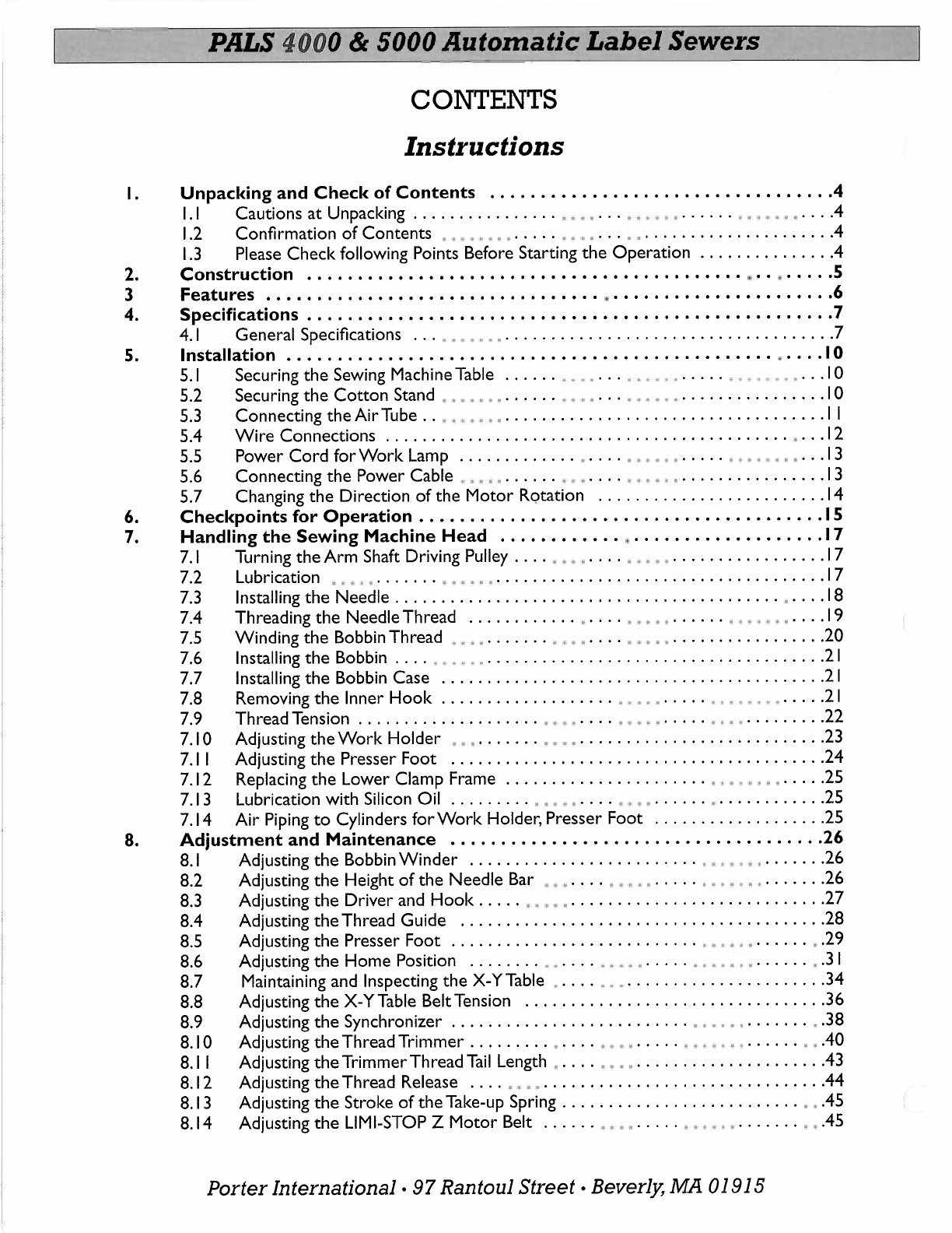
CONTENTS
Instructions
I.
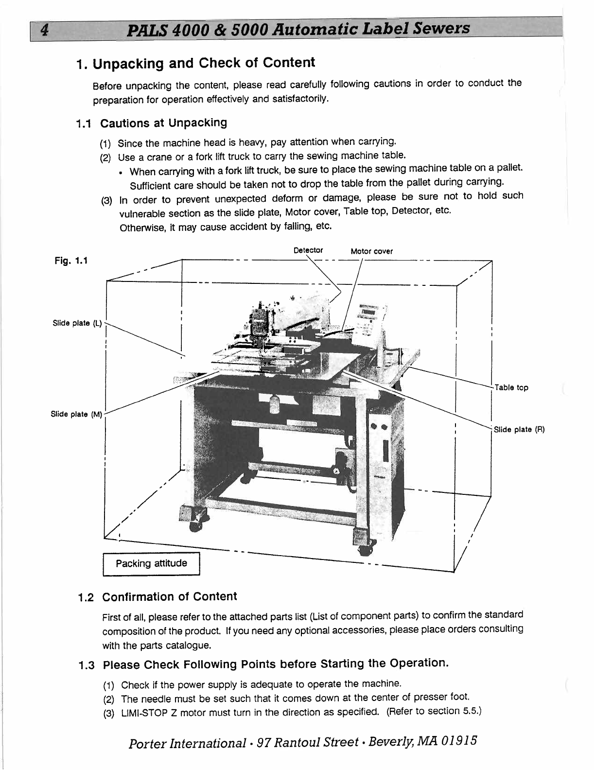
Unpacking and Check
of
Contents
.................................
.4
1.1
Cautions
at
Unpacking . . . . . . . . . . . . . . . . . . . . . . . . • . . . . . . . . . ••
...
.4
1.2
Confirmation
of
Contents
. . . . . . .
....
.•..
...
..
....................
.4
1.3
Please
Check
following Points Before Starting
the
Operation
..............
.4
2.
Construction
. . . . . . . . . . . . . . . . . . . . . . . . . . . . . . . . . . . . . . . . . . . . . .
.....
S
3
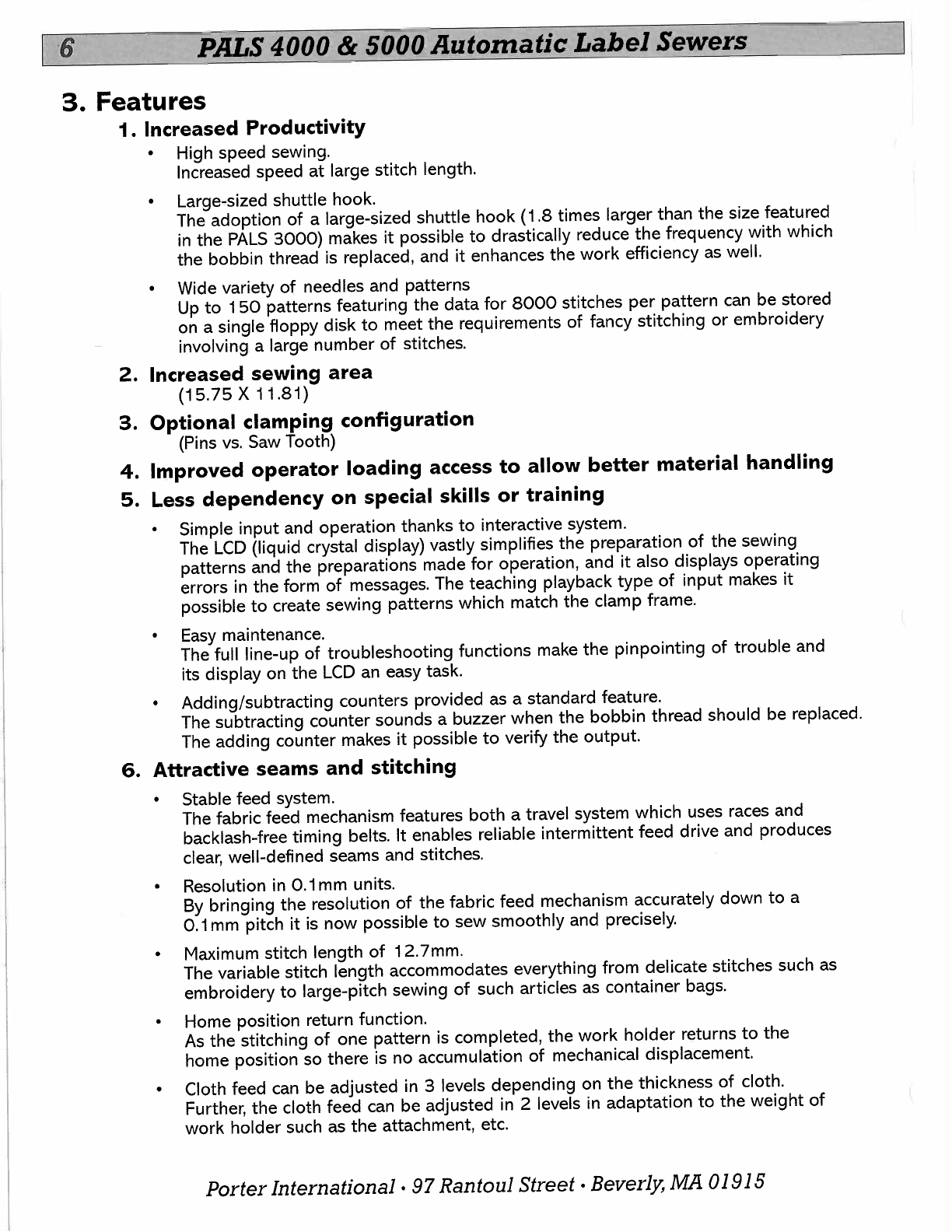
Features
. . . . . . . . . . . . . . . . . . . . . . . . . . . . . . . . . .
.....................
6
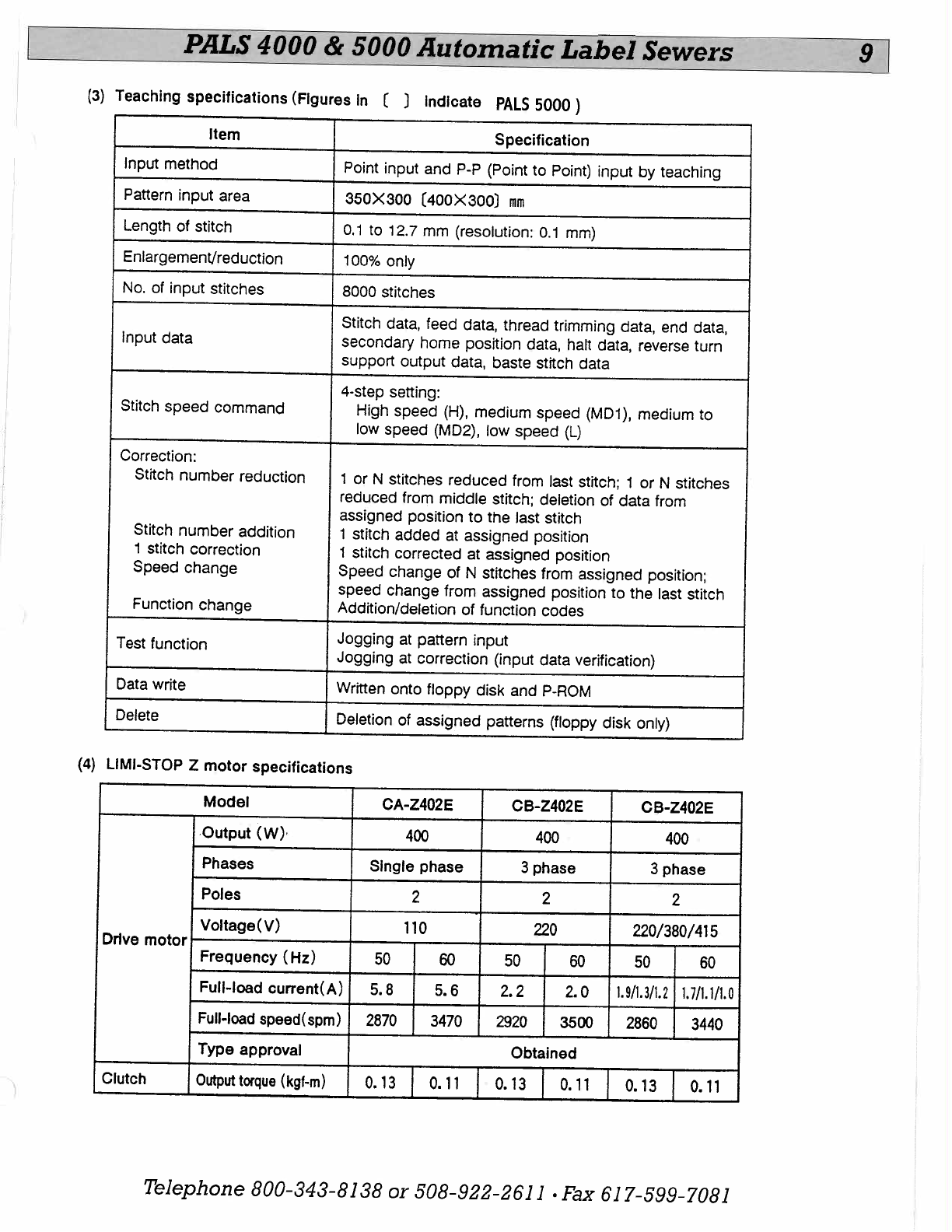
4.
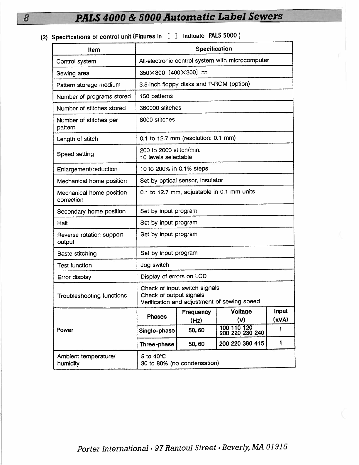
Specifications
....................................•...............
7
4.1
General Specifications . . . . . .
...
...............
.
...................
.7
5.
Installation
................................................
.
....
I0
5.1
Securing
the
Sewing Machine Table . . . . . . . . . . . . . . . . . . . . . . . • . . • ,
...
I0
5.2 Securing
the
Cotton
Stand . . . .
......
....
...
..•...
................
I0
5.3 Connecting
the
AirTube
..
, . •••
...................................
I I
5.4
Wire
Connections
............................................
.
...
12
5.5 Power
Cord
for
Work
Lamp . . . . . . . . . . . . . . . . . • . • . . . . . . . .
...
...
13
5.6 Connecting
the
Power Cable
...
, . . . . . . . • . . . . •. . •
................
13
5.7 Changing
the
Direction
of
the
Motor
Rotation
.........................
14
6.
Checkpoints
for
Operation
........................................
I5
7.
Handling
the
Sewing Machine
Head
............
.
..................
.
17
7.1
Turning
the
Arm Shaft Driving Pulley . . . . . • . . . . . . . . . .
.................
17
7.2 Lubrication . • •, . . . . . . . • .
.•
....................................
17
7.3 Installing
the
Needle
..........................................
.
....
18
7.4 Threading
the
NeedleThread . . . . . . . . . . . . . . . . . . . •. . . . . . . . .
......
.
19
7.5 Winding
the
Bobbin Thread . • . . . . . . . . • • .
...
•.•..
.................
20
7.6 Installing
the
Bobbin . . . . • .
...
.....................................
21
7.7 Installing
the
Bobbin Case
..........................................
21
7.8 Removing
the
Inner
Hook
. . . . . . . . . . . . . . . . . . . . . . . •. . . . . . •• . . •
.....
21
7.9 ThreadTension
....................
•.
....
.•...
.....
•••.
.........
22
7.10 Adjusting
the
Work
Holder •. . . . . . . . . .
...........................
23
7.1
I Adjusting
the
Presser
Foot
.........................................
24
7.12 Replacing
the
Lower Clamp Frame . . . . . . . . . . . . . . . . . . . . . . •. . . .
....
25
7.13 Lubrication with Silicon Oil . . . . . . . . . . . •. . . . • • •
......
.
............
25
7.14 Air Piping
to
Cylinders for
Work
Holder,
Presser
Foot
...................
25
8.
Adjustment
and
Maintenance
.....................................
26
8.1
Adjusting
the
Bobbin
Winder
. . . . . . . . . . . . . . . . . . . . . . . . . . . • • ,
.......
26
8.2 Adjusting
the
Height
of
the
Needle Bar . . . . . • . . • . . . . . . . • . •
..
.......
26
8.3 Adjusting
the
Driver and
Hook
. . . . . • . •
............
.
...............
27
8.4 Adjusting
the
Thread Guide
........................................
28
8.5 Adjusting
the
Presser
Foot
. . . . . . . . . . . . . . . . . . . . . . . . . . . . .
•••
......
, .29
8.6 Adjusting
the
Home
Position
.......
.
..
....
...•
,
.....
, . • . . .
......
. .3 I
8.7 Maintaining and Inspecting
the
X-YTable .
....
..•
......................
34
8.8 Adjusting
the
X-Y Table BeltTension
.................................
36
8.9 Adjusting
the
Synchronizer
..........................
..•..
,
.......
• .38
8.10 Adjusting
the
ThreadTrimmer . . . . . . . . . . . . . . .
.....
.......
......
..
.40
8.1
I Adjusting
the
TrimmerThread
Tail
Length • . . . . . • .
....................
.43
8.12 Adjusting
the
Thread Release
....
..•.
..............................
.44
8.13 Adjusting
the
Stroke
of
the
Take-up Spring
...............
.
....
.
.....
.•
.45
8.14 Adjusting
the
LIMI-STOP
Z
Motor
Belt
......
. ,
..
.....
.•
, . .
.......
.•
.45
Porter
International•
97
Rantoul
Street•
Beverly,
MA
OJ
915