JUKI MS-1261A-DWS User manual

MS-1261A-DWS
INSTRUCTION MANUAL

CONTENTS
1. SPECIFICATIONS............................................................................................................ 1
1-1. Specications of the sewing machine head ..................................................................... 1
1-2. Specications of the control box....................................................................................... 1
2. SETUP.............................................................................................................................. 2
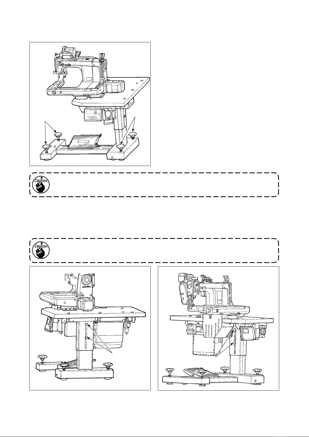
2-1. Setting up the sewing machine.......................................................................................... 2
2-1-1. Adjusting the sewing machine head........................................................................................ 2
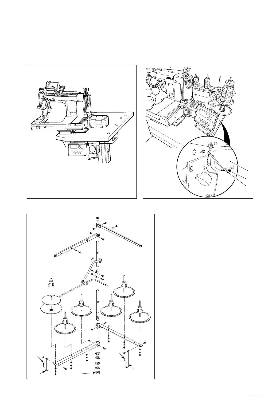
2-1-2. Changing the position of the operation panel ........................................................................3
2-2. Installing the thread stand.................................................................................................. 3
2-3. Oiling and draining of oil .................................................................................................... 4
3. PREPARATION BEFORE SEWING ................................................................................ 5
3-1. Attaching the needle ........................................................................................................... 5
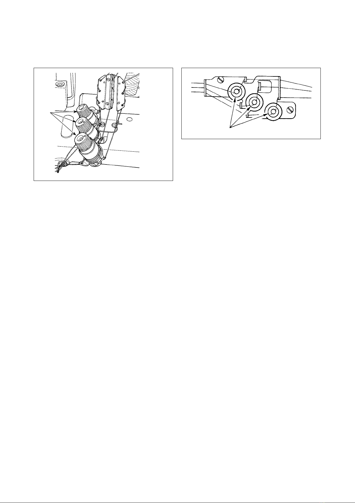
3-2. Threading the machine head.............................................................................................. 6
3-3. Adjusting the thread tension.............................................................................................. 7
3-4. Adjusting the stitch length ................................................................................................. 8
3-5. Adjusting the needle guard ................................................................................................ 9
3-6. Adjusting the looper thread cam...................................................................................... 10
3-7. Adjusting the feed dog height.......................................................................................... 10
3-8. Adjusting the take-up thread tension control lever........................................................ 11
3-9. Adjusting the position of the intermediate tension release lever and needle thread
tension controller .............................................................................................................. 11
3-10. How to adjust the cloth puller .......................................................................................... 12
3-10-1. Adjusting the cloth puller belt and its longitudinal position ............................................. 12
3-10-2. Adjusting the inclination of the cloth puller belt.................................................................13
3-11. LED hand light ................................................................................................................... 13
3-12. To use the sewing machine with a cloth puller for sewing heavy-to medium-weight
materials............................................................................................................................. 14
3-12-1. Replacing the feed dog .........................................................................................................14
3-12-2. Changing the throat plate .....................................................................................................14
3-12-3. Adjusting the difference in height of the presser foot ...................................................... 15
3-12-4. Replacing the needle thread guide ......................................................................................15
3-13. Table of replaceable gauges............................................................................................. 16
3-14. Adjusting the material edge detector .............................................................................. 17
3-15. Needle cooler ..................................................................................................................... 18
3-15-1. Adjusting the position of the blow pipe............................................................................... 18
3-15-2. Adjusting the air ow.............................................................................................................18
3-16. Chain-off thread cutter (suction of thread waste) .......................................................... 18
4. HOW TO USE THE OPERATION PANEL ..................................................................... 19
4-1. Explanation of the operation panel switch ..................................................................... 19
4-2. Operation to be done at rst ............................................................................................ 20
4-2-1. Selection of the language .......................................................................................................20
4-3. How to select a sewing pattern........................................................................................ 23
4-4. How to change the sewing data ....................................................................................... 24
4-4-1. Method of changing the sewing data.....................................................................................24
4-4-2. Method of selecting a specic sewing data item..................................................................24
4-4-3. How to change the part number, process or comment for the sewing pattern data......... 26
i

4-4-4. How to carry out teaching of the multi-layered section of material....................................27
4-4-5. Sewing data on a free sewing pattern ................................................................................... 28
4-4-6. How to edit a step sewing pattern..........................................................................................34
4-4-7. How to carry out the teaching of the number of stitches ....................................................38
4-4-8. List of sewing data...................................................................................................................39
4-5. How to edit/check the data other than sewing data ....................................................... 44
4-5-1. Memory switch data.................................................................................................................45
4-5-2. Counter function ......................................................................................................................50
4-5-3. How to copy / newly create a pattern.....................................................................................54
4-5-4. How to use the warning function ...........................................................................................56
4-5-5. How to use the F key ...............................................................................................................59
4-5-6. Checking the version information..........................................................................................62
4-5-7. Adjusting the contrast of the LCD of the operation panel ...................................................62
4-5-8. Communication function......................................................................................................... 63
4-6. Information......................................................................................................................... 64
4-6-1. Simple lock ...............................................................................................................................64
4-7. List of errors ...................................................................................................................... 65
4-8. External interface .............................................................................................................. 69
4-8-1. USB ...........................................................................................................................................69
4-8-2. NFC............................................................................................................................................70
5. CARE ............................................................................................................................. 71
5-1. Oil quantity in the oil tank................................................................................................. 71
5-2. Lubricating the chain off thread cutter............................................................................ 71
5-3. Changing the cloth puller belt.......................................................................................... 72
5-4. Cleaning ............................................................................................................................. 73
5-5. Replacing the fuse............................................................................................................. 74
ii

– 1 –
Model MS-1261A △DWS MS-1261AM △DWS
Application For heavy- to extra-heavy-weight materials For medium- to heavy-weight materials
Max. sewing speed 5500 sti/min
Number of needle 3
Needle UY×128GAS #16 to 22
(Standard #21)
UY×128GAS #16 to 21
(Standard #19)
Cloth puller system Electronic control
Height of presser foot 10 mm
Stitch length 1.4 to 4.2 mm
Needle gauge 6.4 mm(1/4)
Circumference of cylinder 194 mm
Lubricating oil JUKI NEW DEFRIX OIL No. 1 or JUKI CORPORATION GENUINE OIL 7
Noise
- Equivalent continuous emission sound pressure level (LpA) at the workstation:
A-weighted value of 84.5 dB ; (Includes KpA = 2.5 dB) ; according to ISO 10821- C.6.2
-ISO 11204 GR2 at 4,500 sti/min.
- Sound power level (LWA);
A-weighted value of 91.0 dB; (Includes KWA = 2.5 dB); according to ISO 10821- C.6.2
-ISO 3744 GR2 at 4,500 sti/min.
1. SPECIFICATIONS
1-1. Specications of the sewing machine head
1-2. Specications of the control box
Supply
voltage
3-phase
220 to 240V
Single phase
220 to 240V
Single phase
220 to 240V CE
Frequency 50Hz/60Hz 50Hz/60Hz 50Hz/60Hz
Operating
environment
Temperature : 0 to 35˚C
Humidity : 90% or less
Temperature : 0 to 35˚C
Humidity : 90% or less
Temperature : 0 to 35˚C
Humidity : 90% or less
Input 820VA 820VA 680VA
MS-1261A DWS
Sewing material type
Space Extra heavy-weight materials
(standard)
M Heavy-weight materials
Needle gauge
F 6.4mm(1/4)

❶❶
❶❶
– 2 –
2. SETUP
2-1. Setting up the sewing machine
Fix the sewing machine on the oor with adjuster
bolts ❶(four pieces).
2-1-1. Adjusting the sewing machine head
Loosen bolts ❶ (four pieces) and adjust the height of sewing machine.
1. Total weight of the sewing machine, machine table and control box is 110 kg or more. It is
necessary to adjust the sewing machine height with four or more persons.
2. Adjust the sewing machine height so that it is levelled.
Be sure to move the sewing machine with two or more persons.

❶
❷
❸
❶
– 3 –
1) Assemble the thread stand device. Fit it
in the hole in the table. Tighten locknut
❶ so that the thread stand does not uc-
tuate.
2) Fix thread stand bracket ❷on the table
with wood screw ❸.
2-2. Installing the thread stand
2-1-2. Changing the position of the operation panel
The operation panel has been installed on the undersurface of the sewing machine table at the time of deliv-
ery. When you install it on the top surface of the sewing machine table, it is necessary to pass panel cord ❶
through hole ❸in the lower section of motor cover ❷.
At the time of shipment
(undersurface of the sewing machine table)
In the case of changing the position of the operation
panel to the top surface of the sewing machine table
❶
❸
❷
❸
❷

❶
H
L
A
B
❶
❶
❷
❸
– 4 –
2-3. Oiling and draining of oil
Before putting your sewing machine into use, ll the oil tank with the oil supplied with the sewing machine.
1) Feeding oil
Detach oil sight window ❶.
Put JUKI New Defrix Oil
No. 1 or JUKI CORPORA-
TION GENUINE OIL 7 into
the oil tank through the oil
hole.
Fill the oil tank with the aforementioned oil until
the oil surface reaches between two indicator
lines (upper marker line A and lower marker line
B). After lling the oil tank, be sure to t oil sight
window ❶ back to its home position.
2) Draining the oil and changing the oil
Firstly, loosen wood screws ❶ (three pieces). Detach oil tank cover ❷. Then, loosen screw ❸. Discharge
the oil remaining in the oil tank completely. After discharging the oil, be sure to tighten screw ❸.
In order to increase durability of the sewing machine, it is recommended to change the oil with new oil af-
ter the rst four weeks have passed since the rst use of the sewing machine, then carry out an oil change
at an appropriate interval.
The waste oil must be disposed of properly according to the relevant laws and regulations in
your area.

– 5 –
Make a choice of the needle count in accordance
with thickness of the thread and type of the material
to be used.
1) Turn the hand wheel until the needle bar reaches
to the highest position of its stroke.
2) Loosen screw ❷in the needle clamp, and turn
needles ❶so that the long groove on the respec-
tive needles is brought in front of you.
3) Insert the needles into the needle clamp hole until
they will go no further.
4) Securely tighten needle clamp screw ❷.
❶
❷Long
groove
3-1. Attaching the needle
3. PREPARATION BEFORE SEWING
WARNING :
Turn OFF the power before starting the work so as to prevent accidents caused by abrupt start of the
sewing machine.

❶
MA-1261A
MA-1261AM
a
b
c
a
b
c
a
b
c
a
b
c
a
b
c
a'
b'
c'
a'
b'
c'
a'
b'
c'
c'
b'
a'
a'
b'
c'
c'
b'
a'
❻
❹
❸
❷
①
❶
③
④
④
❷
②
❺
Pass the needle thread on the sewing machine head in numerical order form ①.
Pass the looper thread on the sewing machine head in numerical order from ❶.
a = Right-hand needle thread b = Intermediate needle thread c = Left-hand needle thread
a' = Right-hand looper thread b' = Intermediate looper thread c' = Left-hand looper thread
– 6 –
3-2. Threading the machine head
WARNING :
Turn OFF the power before starting the work so as to prevent accidents caused by abrupt start of the
sewing machine.

– 7 –
1) Adjusting the needle thread tension
Turn thread tension nut ❶clockwise to increase or
counterclockwise to reduce the needle thread ten-
sion.
3-3. Adjusting the thread tension
❷
2) Adjusting the looper thread tension
Turn tension adjusting screw ❷clockwise to in-
crease or counterclockwise to reduce the looper
thread tension.
❶

Marker dot on the
handwheel 。。 。。。 。。。。
Stitch length 2 3 4
*The aforementioned marker dot is only a
reference. Be aware that the adjustment result
may differ with the material used.
For the stitch length, adjust it on the sewing machine alone. Then, adjust the feed amount of the cloth puller
belt. Then, nely adjust the stitch length while visually checking the nished state of sewing material.
■Adjusting the stitch length of the sewing machine alone
– 8 –
3-4. Adjusting the stitch length
1) Remove screw ❸, and loosen the lock screw in
the feed rock cam.
2) Lightly pressing push-button ❶, turn the hand-
wheel by hand.
3) When push-button ❶bites, the sewing machine
will stop running.
4) In the aforementioned state, further pressing the
push-button ❶, turn the handwheel by hand.
5) Aligning the marker dot (to be used for reference)
on the handwheel with marker line ❷on the tim-
ing belt cover, release your hand from push-button
❶.
6) Tighten the lock screw in the feed rock cam.
7) Attach screw ❸in place.
Lock screw
WARNING :
Turn OFF the power before starting the work so as to prevent accidents caused by abrupt start of the
sewing machine.
❸
❶
❷
1. Never press the push-button ❶while
the sewing machine is in operation.
2. Be sure to operate the sewing machine
after tightening the lock screw.
3. Never operate the machine with screw
❸removed.
4. The lock screw has a locking setscrew
to prevent the screw from loosening.
The lock screw head can be damaged
if you forcefully remove it.

– 9 –
3-5. Adjusting the needle guard
The needle guard has been mounted on the feed dog. It therefore necessary to adjust the needle guard
whenever the feed amount is changed.
(Adjusting the clearance provided between the needle and the looper)
1) Turn the hand wheel to make the top end of the looper align with the center of the needle.
2) Loosen screw ❶, move the entire unit of the needle guard to the right or left to make the needle guard
press the needle so that the clearance of 0.1 to 0.15 mm is provided between the looper and the needle.(0.05
to 0.1 mm for MS-1261AM)
(Adjusting the vertical position of the needle guard)
1) Turn the handwheel to bring the needle guard at a position where the needle guard starts pressing the
needle.
2) Loosen screw ❷, and move the entire unit of the needle guard up or down so that the needle guard is lo-
cated at a position where it does not press and deform needle thread loops (just below the needle eyelet).
(Adjusting the clearances between the respective needles and loopers)
If the clearances between the respective loopers and needles are not equal after the clearance between
each needle and looper has been adjusted by moving the entire unit of the needle guard, adjust so that the
equal clearance is provided between the respective loopers and needles following the steps described below.
1) Turn the handwheel to make the top end of the looper align with the center of the needle.
2) Loosen screw ❸, move the respective needle guards to adjust so that the equal clearance is provided
between the respective needles and loouers.
MS-1261A :
0.1 ~0.15mm
MS-1261AM :
0.05 ~0.1mm
Press the
section below
the needle
eyelet.
❶
❷
❸
WARNING :
Turn OFF the power before starting the work so as to prevent accidents caused by abrupt start of the
sewing machine.

– 10 –
3-6. Adjusting the looper thread cam
Loosen screw ❷, and adjust looper thread cam ❶
so that the looper starts drawing the thread when it
starts returning to its home position after it has pro-
jected the most.
■ Adjusting the looper thread cam thread guide
1) Align the end face of thread guide ❻to the marker
line on thread guide ❻. Then adjust thread guide
❺ so that its end face is ush with the end face of
thread guide ❻.
The standard position of the thread guide is ob-
tained when the end face of the thread guide is
aligned with the center marker line.
2) When using a cotton thread, loosen screws ❸
and ❹, and align the end faces of thread guides
❺and ❻to the marker line located far side. At
this time, it is not necessary to re adjust the looper
thread cam timing.
Position of the looper thread
can for cotton thread
Standard position
of the looper thread
cam
❶ ❹
❷
❸
❺
❻
Align the marker line with
the bottom end of the
thread guide.
WARNING :
Turn OFF the power before starting the work so as to prevent accidents caused by abrupt start of the
sewing machine.
The top end of the feed dog should rise 1.4 mm above the surface of the throat plate when the feed dog is in
the highest position of its stroke.
■ Adjusting the feed dog height
1) Loosen screw ❶in the side plate of the bed and remove it.
2) Remove the screw ❶, and loosen a hexagon socket head screw under the screw ❶with an L-shaped
hexagon wrench key.
3) Adjust the feed dog height by turning feed driving amount adjusting shaft ❷.
4) Fix the shaft with the hexagon socket head screw and tighten screw ❶.
1.4mm
Throat plate
Feed dog Higher Lower
❶
❷
WARNING :
Turn OFF the power before starting the work so as to prevent accidents caused by abrupt start of the
sewing machine.
3-7. Adjusting the feed dog height

– 11 –
3-8. Adjusting the take-up thread tension control lever
Needle
thread loop
Lowest
point dead
MS-1261A
: 3 mm
MS-1261AM
: 0 mm
❶❷
❸
WARNING :
Turn OFF the power before starting the work so as to prevent accidents caused by abrupt start of the
sewing machine.
Needle thread loop size is determined
by adjusting the position of take-up
thread tension control lever ❶.
The needle thread loop size changes
in accordance with the thread and
material used. So, adjust the thread
loop size upon occasion.
1) Loosen two screws ❷, and adjust
the position of the thread take-
up lever guide by moving it up or
down.
3-9. Adjusting the position of the intermediate tension release lever and needle thread ten-
sion controller
Adjust the position of intermediate thread tension releasing lever ❶and thread guide ❹of the needle thread
tension controller as described below.
WARNING :
Turn OFF the power before starting the work so as to prevent accidents caused by abrupt start of the
sewing machine.
1) Turn the handwheel to bring the nee-
dle bar to the highest dead point.
2) Remove rubber cap ❷. Loosen
setscrew ❻locating under the rub-
ber cap. Adjust intermediate thread
tension release lever ❶so that the
thread coming out of intermediate
needle thread guide ❸is horizontal.
3) Then, loosen two screws ❺, and
adjust the position of thread guide ❹
of the needle thread tension control-
ler so that the thread coming from
intermediate thread tension releasing
lever ❶makes a beeline.
❺
❶
❹❸
Highest dead
point
2) Adjust so that, when the needle bar is in the lowest dead point, the top end of the thread tension control
lever is positioned 3 mm above the top end of thread hole in needle bar thread take-up lever ❸. (0 mm for
MS-1261AM)
3) Lowering thread tension control lever ❶decrease the loop size. Lifting the lever increases it.
❷
❻

❶
❷❸
❹
Slightly sinks
❷SM9051603SC Screw
❸NM6050003SC Nut
❹Cloth puller base
binding part Anti-vibration rubber
– 12 –
3 to 4mm
Feed dog of
the sewing
machine
(largest feed
pitch)
Throat plate
Cloth puller belt
3-10. How to adjust the cloth puller
1) Loosen hexagon head setscrews ❶(three piec-
es).
Maximize the feed amount of the main body of
sewing machine. Adjust the feed amount to 3 to
4 mm by moving the cloth puller back and forth
when the feed dog approaches closest to the belt.
3-10-1. Adjusting the cloth puller belt and its longitudinal position
2) Loosen screw ❷ and adjust the longitudinal posi-
tion of the cloth puller so that the head of screw ❷
comes in contact with rubber ❹to such an extent
that rubber ❹slightly sinks.
3) Tighten nut ❸to secure the cloth puller.

❶
❷
– 13 –
3-11. LED hand light
WARNING :
When adjusting the sensor, neither put your hand close to the needle entry area nor put your foot on
the pedal in order to protect against injuries.
* This LED is intended to improve operability
of the sewing machine and is not intended for
maintenance.
The sewing machine is provided as standard with an
LED light which illuminates the needle entry area.
Intensity adjustment and turn-off of the light is carried
out by pressing switch ❶. Every time the switch is
pressed, the light is adjusted in intensity in ve steps
and is turned off in turn.
[Change of intensity]
1⇒...... 4 ⇒5⇒1
Bright ⇒...... Dim ⇒Off ⇒Bright
In this way, every time the switch ❶is pressed, the
hand lamp status is changed in repetition.
θ
θ
3-10-2. Adjusting the inclination of the cloth puller belt
1) Loosen hexagon head setscrews ❷(two pieces).
Rotate the cloth puller so that it is in parallel with
the feed dog.
If the cloth puller inclines (as shown
with θ), the chain-off thread skipping
may occur.

❶❶
❷
– 14 –
3-12. To use the sewing machine with a cloth puller for sewing heavy-to medium-weight ma-
terials
The MS-1261A has been developed to sew extra heavy-weight materials as standard. Various kinds of gaug-
es have been prepared to enable the machine to be used for sewing heavy- to medium-weight materials. Re-
place the gauge, when sewing heavy- to mediumweight materials, following the procedure described below.
3-12-1. Replacing the feed dog
Remove the throat plate. Loosen screw ❶in the
feed dog and remove the feed dog. Then, replace
the feed dog with an appropriate one.
Each of the feed dogs for heavy- to
medium-weight materials has been
designed so that it can be used only
by replacing it without adjusting the
feed dog height. However, it is really
necessary to adjust the feed dog height,
refer to "3-7. Adjusting the feed dog
height" p. 10
★
To change the height in difference on the
righthand side of the feed dog
Loosen two serews ❶ in the adjusting feed dog and
remove spacer ❷(plate thickness: 0.5 mm).
Many different types of spacers are available.
WARNING :
Turn OFF the power before starting the work so as to prevent accidents caused by abrupt start of the
sewing machine.
3-12-2. Changing the throat plate
Detach throat plate setscrews ❶(two pieces) and
❷(one piece). Then, change the throat plate with an
appropriate one.
❶
❷

– 15 –
3-12-3. Adjusting the difference in height of the presser foot
Remove two screws ❷that are used to retain ad-
justing presser foot ❶, and adjust the difference in
height of the presser foot by replacing spacer ❸.
Thicknesses of spacers that match the respective
throat plates and feed dogs are as shown in the
table.
No. Plate Thickness Specication
1 1.0mm Extra heavy-weight mate-
rials (standard)
2 0.5mm Heavy-weight materials
3 None Medium-weight materials
To replace spacer ❸with a spacer (0.5 mm or
none), replace screw ❷with a shorter one (L=3.0
mm SS5060310SP).
3-12-4. Replacing the needle thread guide
When sewing a medium-weight material using a thin
thread, larger needle thread loops will be produced
and they will be likely to tilt causing stitch skipping.
To prevent the aforementioned trouble, replace
thread guide ❶located above the needle clamp with
an appropriate one.
Loosen screw ❷ that is used to x thread guide ❶,
and replace the thread guide with thread guide ❸for
medium-weight materials.
❷
(Standard L: 3.5 mm)
❸
❶
❶
❷
❸

– 16 –
1. Spacer for presser foot 2. Setscrews
No. Plate thickness (mm) Part No. Part name Part No. Plate
①0.3 12973509 Presser foot adjusting plate B SS5060310SP 2
②0.5 12973608 Presser foot adjusting plate C 2
③0.8 12973707 Presser foot adjusting plate D
SS5060410SP
2
④1.0 12962106 Presser foot adjusting plate A 2
⑤1.2 12973806 Presser foot adjusting plate E 2
3. Spacer for feed dog
No. Plate thickness (mm) Part No. Part name
①0.3 12975702 Feed dog adjusting plate B
②0.5 12964102 Feed dog adjusting plate A
③0.8 12975801 Feed dog adjusting plate C
④1.0 12975900 Feed dog adjusting plate D
Code of folder
M297 — For medium-weight materials
(Equipped on MS-1261AM as standard)
M298 — For heavy-weight materials (Optional)
M299 — For extra-heavy-weight materials
(Equipped on MS-1261A as standard)
1 2 3
Part name Folder (asm.)
Needle gauge
M297 M298 M299
Code inch mm
F 1/4 6.4 MAM2970EEBA MAM2980BBBA MAM2990BBBA
3-13. Table of replaceable gauges
Part name Needle clamp (asm.) Throat plate Presser foot (asm.)
(with nger guard) Feed dog Needle thread guide
Model Application
Needle gauge
Code inch mm
MS-1261A Extra-heavy-weight materials F 1/4 6.4 12956256 40202942 40202943 12963351
MS-1261A Heavy-weight materials F 1/4 6.4 12956256 40204587 40204601 12974150
MS-1261AM Medium-heavy-weight materials F 1/4 6.4 12956256 40204592 40205581 12974952 B1130051000
Part name Looper (L) (asm.) Looper (R) (asm.) Looper (C) (asm.)
Model Application
Needle gauge Mark Mark Mark
Code inch mm Mark
No.
Mark
No.
Mark
No.
MS-1261A Extra-heavy-weight materials F 1/4 6.4 12968558 1 12968855 1 12969150 1
MS-1261A Heavy-weight materials F 1/4 6.4 12968558 1 12968855 1 12969150 1
MS-1261AM Medium-heavy-weight materials F 1/4 6.4 12968558 1 12968855 1 12969150 1
Options
Folder

– 17 –
3-14. Adjusting the material edge detector
Material edge detector ❶detects the presence /
absence of the material at the beginning and end of
sewing.
When the material is present, the green LED (A) and
the orange LED (B) light up at all times.
When the material is absent, only the green LED (A)
lights up.
The detecting device of the sewing machine has
been factory-adjusted at the time of shipment so
that it detects the presence / absence of the material
without additional adjustment. However, the detect-
ing device may fail to detect the material properly
depending on the type of material used.
In such a case, adjust the detecting device of the
sewing machine by turning control knob ❷.
[Adjustment procedure]
* The orange LED (B) lights up even when the ma-
terial is not present on the sewing machine.
→ Turn control knob ❷toward the "min".
* The orange LED (B) goes out even when the ma-
terial is present on the sewing machine.
→ Turn control knob ❷toward the "max".
Material is
present
Material is
absent
min max
❶
❷
WARNING :
When adjusting the sensor, neither put your hand close to the needle entry area nor put your foot on
the pedal in order to protect against injuries.
DL
min max
A
DL
min max
AB
Table of contents
Other JUKI Sewing Machine manuals

JUKI
JUKI LU-2860-7 User manual

JUKI
JUKI HZL-F series User manual

JUKI
JUKI DLN-415 User manual

JUKI
JUKI L-1D Series User manual

JUKI
JUKI MO-6900 Series User manual

JUKI
JUKI MO-735 User manual

JUKI
JUKI LH-4128-7 Quick start guide

JUKI
JUKI AK118 User manual

JUKI
JUKI PS-800-13085 User manual

JUKI
JUKI HZL-K85 User manual

JUKI
JUKI MO-634DEV User manual

JUKI
JUKI AC-172NN-1790 User manual

JUKI
JUKI APW-896N/IP-420 User manual

JUKI
JUKI MCS-1800 User manual

JUKI
JUKI AMS-221F3020RSZ/AW-3 User manual

JUKI
JUKI MS-191; MS-191A; MS-261; MS-261J User manual

JUKI
JUKI LZH-1290 User manual

JUKI
JUKI DDL-8700-7 User manual

JUKI
JUKI MS-1190/V045 User manual

JUKI
JUKI LBH-1795AN User manual