Portwell WADE-8021 User manual

WADE-8021
User's Manual
Version 1.0
Copyright © Portwell, Inc., 2014. All rights reserved.
All other brand names are registered trademarks of their respective owners.

Preface
Table of Contents
How to Use This Manual
Chapter 1 System Overview.......................................................................................................1-1
1.1 Check List........................................................................................................... 1-1
1.2 Product Specification........................................................................................ 1-1
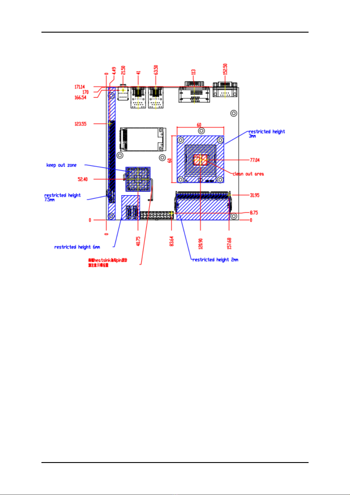
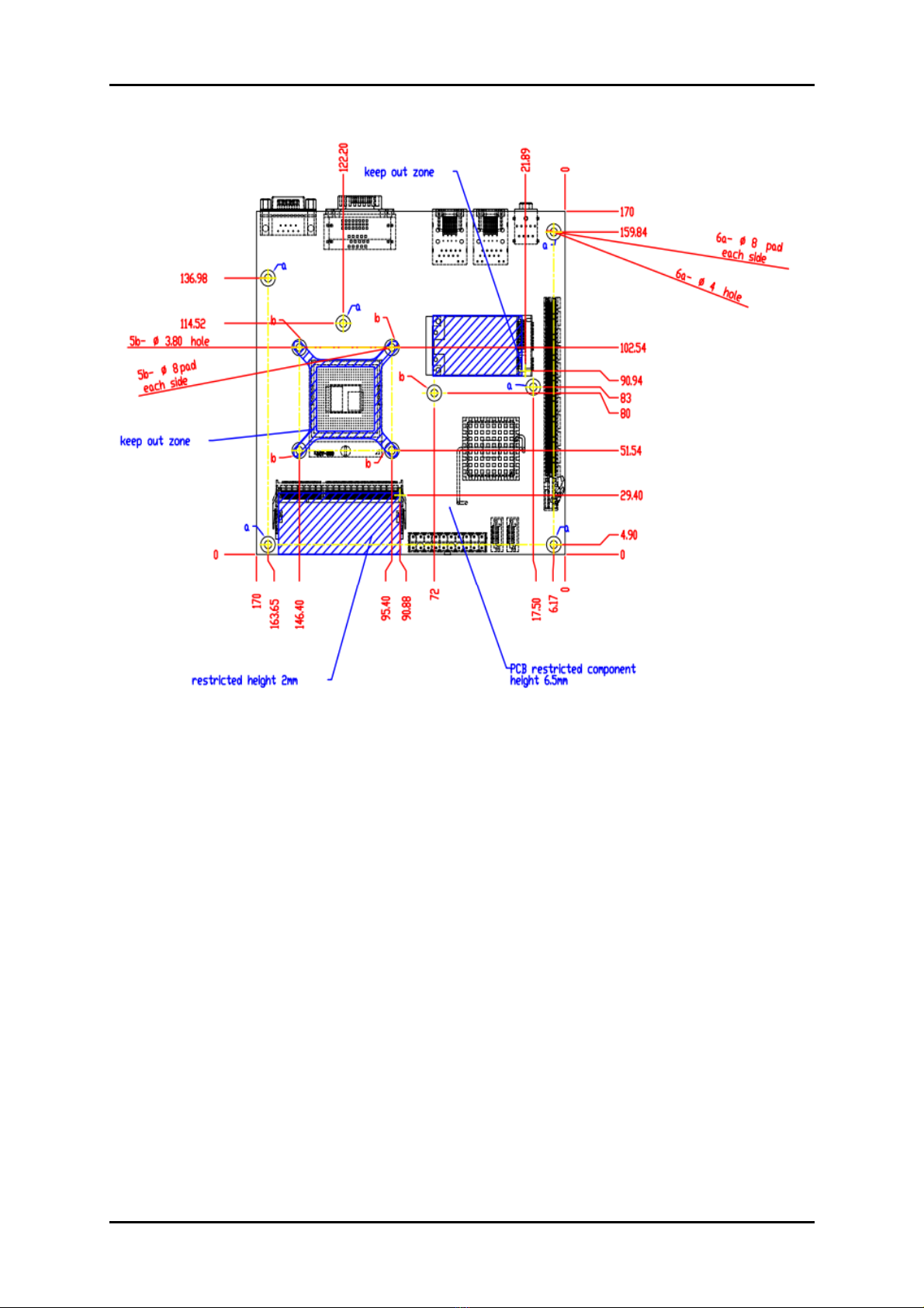
1.2.1 Mechanical Drawing................................................................................ 1-4
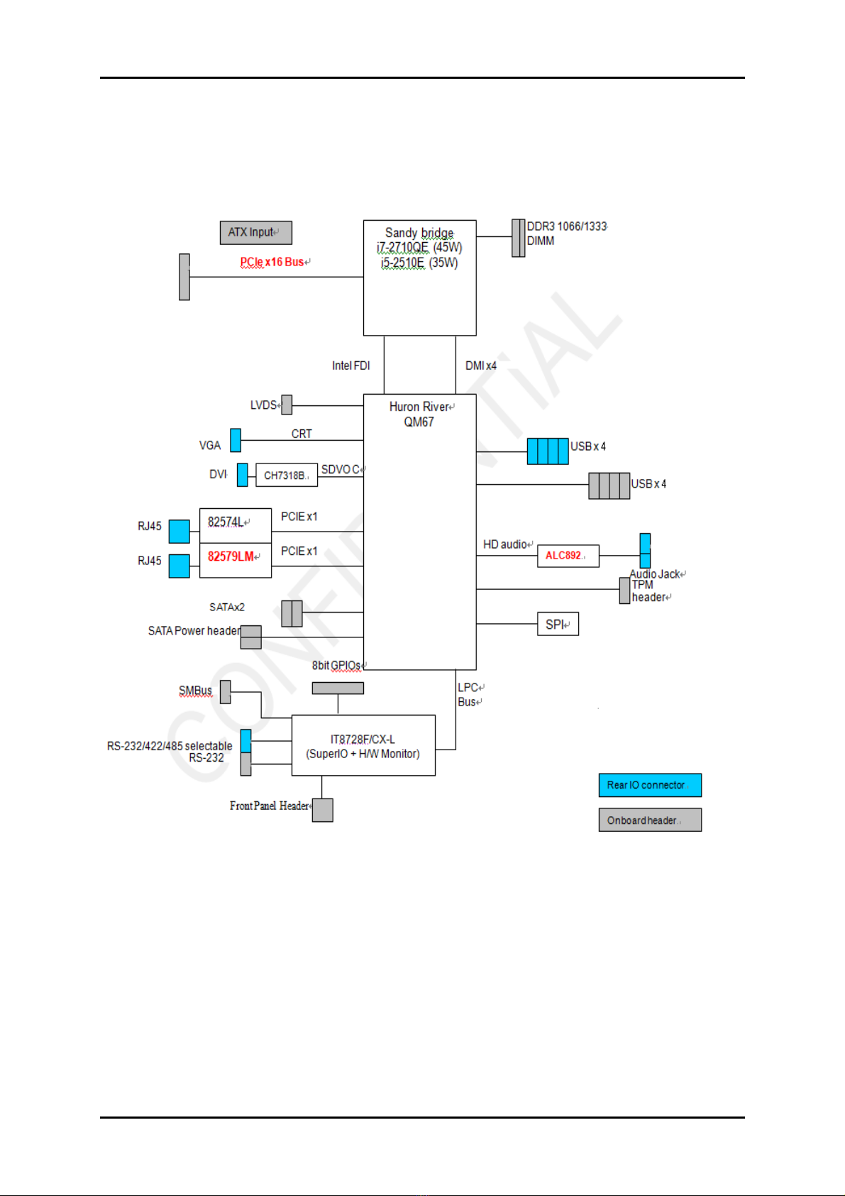
1.3 System Architecture.......................................................................................... 1-6
Chapter 2 Hardware Configuration ...........................................................................................2-1
2.1 Jumper Setting................................................................................................... 2-1
2.2 Connector Allocation........................................................................................ 2-4
Chapter 3 System Installation....................................................................................................3-1
3.1 Intel® Socket P 32 nm (988 Pin) Processor ................................................... 3-1
3.2 Main Memory.................................................................................................... 3-2
3.3 Installing the Single Board Computer............................................................ 3-3
3.3.1 Chipset Component Driver .................................................................... 3-3
3.3.2 Intel Integrated Graphics GMCH Chip ................................................ 3-3
3.3.3 Intel Gigabit Ethernet Controller........................................................... 3-3
3.3.4 Audio Controller...................................................................................... 3-4
3.3.5 Intel® Active Management Technology (Intel® AMT)...................... 3-4
3.4 Clear CMOS Operation .................................................................................... 3-4
3.5 WDT Function ................................................................................................... 3-4
3.6 GPIO.................................................................................................................... 3-6
Chapter 4 BIOS Setup Information............................................................................................4-1
4.1 Entering Setup -- Launch System Setup ........................................................ 4-1
4.2 Main .................................................................................................................... 4-2
4.3 Configuration .................................................................................................... 4-1
4.4 Boot ................................................................................................................... 4-23
4.5 Security ............................................................................................................. 4-25
4.6 Save & Exit ....................................................................................................... 4-26
Chapter 5 Troubleshooting........................................................................................................5-1
5.1 Hardware Quick Installation........................................................................... 5-1
5.2 BIOS Setting ....................................................................................................... 5-2
5.3 FAQ ..................................................................................................................... 5-3

Preface
How to Use This Manual
The manual describes how to configure your WADE-8021 system board to meet
various operating requirements. It is divided into five chapters, with each chapter
addressing a basic concept and operation of Single Host Board.
Chapter 1: System Overview. Presents what you have in the box and give you an
overview of the product specifications and basic system architecture for this series
model of single host board.
Chapter 2: Hardware Configuration. Show the definitions and locations of Jumpers
and Connectors that you can easily configure your system.
Chapter 3: System Installation. Describes how to properly mount the CPU, main
memory and Compact Flash to get a safe installation and provides a programming
guide of Watch Dog Timer function.
Chapter 4: BIOS Setup Information. Specifies the meaning of each setup
parameters, how to get advanced BIOS performance and update new BIOS. In
addition, POST checkpoint list will give users some guidelines of trouble-shooting.
Chapter 5: Troubleshooting. Provide various of useful tips to quickly get
WADE-8021running with success. As basic hardware installation has been
addressed in Chapter 3, this chapter will basically focus on system integration issues,
in terms of backplane setup, BIOS setting, and OS diagnostics.
The content of this manual is subject to change without prior notice. These changes
will be incorporated in new editions of the document. The vendor may make
supplement or change in the products described in this document at any time.

System Overview
WADE-8021 User’s Manual 1-1
Chapter 1
System Overview
Powell Inc., a world-leading innovator in the Industrial PC (IPC) market and a
member of the Intel® Communications Alliance, has launched its new WADE-8021 in
response to market demand for a simplified embedded system board (ESB) that
combines a smaller footprint, lower power consumption, robust computing power
and with longevity support.
Based on latest mobile Intel® QM67 Express chipset, WADE-8021 takes advantage of
Intel® Core™ i5 / i7 processor which has high performance and excellent power
management features. WADE-8021 not only supports dual display by VGA / DVI /
LVDS and the third display via PCI-Express expansion slot. In addition, with its
display-enriched interface, WADE-8021 can support various multimedia devices.
Built with 32nm Intel® Core™ i5 / i7 processor and Mobile Intel® QM67 Express
chipset, WADE-8021 can provide the best solution for multiple applications such as
POS, DVR, Mobile Kiosk, Lottery, Gaming and Digital Signage.
1.1 Check List
The WADE-8021 package should cover the following basic items
One WADE-8021 Mini-ITX Main Board
If any of these items is damaged or missing, please contact your vendor and keep all
packing materials for future replacement and maintenance.
1.2 Product Specification
Main Processor
- Intel®Core™ i5 / i7 processor
- CPU clock bus: 1333/1066 MHz
Chipset
Intel®QM67 Express chipset
System BIOS
AMI BIOS
Main Memory
Two 204-pin DDR3 SODIMM socket support up to 8GB dual channel 1333/1066
MHz memory

System Overview
WADE-8021 User’s Manual 1-2
Expansion Interface
- One PCI-E x16 slot
- One Mini PCI-E slot
SATA Interface
Two SATA ports
Serial Port
Support one RS232 ports on board and one RS232/422/485 on rear I/O
USB Interface
Support eight USB (Universal Serial Bus) ports, four on rear I/O and four on
board header for internal devices
Audio Interface
Mic-In and Line-Out on rear I/O
Watch Dog Timer
- Support WDT function through software programming for enable/disable and
interval setting
- General system reset
On-board Ethernet LAN
Two Gigabit Ethernet (10/100/1000 Mbits/sec) LAN ports using Intel 82574L and
82579LM GbE Ethernet Controller
High Drive GPIO
Onboard programmable 16-bit Digital I/Os (8x In/Out)
Cooling Fans
Support one 4-pin power connector for CPU cooler and one 3-pin power
connector for system fan
System Monitoring Feature
Monitor system temperature and major power sources.
Outline Dimension (L x W)
170mm(6.69’’) x 170mm(6.69’’)
Power Requirements
Configuration
CPU Type Intel(R) Core(TM) i5-2510E CPU @ 2.5GHz L3 Cache 3M
SBC BIOS 4.6.4 08/03/2011
Memory Transcend TS256MSK64V1U(SEC K481G0846G) DDR3 1066
2 GB
VGA Card Onboard Intel® HD Graphics Family (Sandy Bridge)
VGA Driver Onboard Intel® HD Graphics Family Version 6.14.10.5328
LAN Card Onboard Intel®
82574L/82579LM Gi
g
abit Network Connection
Ctll
LAN Driver Intel® 82574L/82579LM Gigabit Network Connection
Version 11.7.32.0/11.8.84.0

System Overview
WADE-8021 User’s Manual 1-3
Audio Card Onboard Realtek ALC662 High Definition Audio Controller
Audio Driver Realtek ALC662 High Definition Audio Version 5.10.0.6257
Chip Driver Intel® Chipset Device Software Version 9.2.0.1019
USB 2.0 Driver Intel® 6 Series/C200 Series Chipset Family USB Enhanced
Host Controller Version 9.2.0.1013
SATA HDD WD WD1002FEX 1TB
CDROM LITE-ON LH-20A1S
Power Supply FSP400-60PFN
CPU Type Intel(R) Core(TM) i5-2510E CPU @ 2.5GHz L3 Cache 3M
SBC BIOS 4.6.4 08/03/2011
Item Power ON
Full Loading
10Min
Full Loading
30Min
CPU +12V 2.51A 4.44A 4.65A
System +12V 1.79A 0.25A 0.32A
System +3.3V 0.95A 0.69A 0.81A
System +5V 1.73A 2.26A 2.46A
System+ Device +12V 4.75A 1.20A 1.74A
System+ Device +5V 2.69A 3.20A 3.63A
USB Loading Test 4.77 V/ 500 mA
Operating Temperature
0 °C ~ 60 °C
Storage temperature
-20 ~ 80 °C
Relative Humidity
0% ~ 90%, non-condensing

System Overview
WADE-8021 User’s Manual 1-4
1.2.1 Mechanical Drawing

System Overview
WADE-8021 User’s Manual 1-5

System Overview
WADE-8021 User’s Manual 1-6
1.3 System Architecture
All of details operating relations are shown in WADE-8021 System Block Diagram.
WADE-8021 System Block Diagram

Hardware Configuration
WADE-8021 User’s Manual 2-1
Chapter 2
Hardware Configuration
This chapter gives the definitions and shows the positions of jumpers, headers and
connectors. All of the configuration jumpers on WADE-8021 are in the proper
position. The default settings shipped from factory are marked with an asterisk ().
2.1 Jumper Setting
In general, jumpers on the single board computer are used to select options for
certain features. Some of the jumpers are designed to be user-configurable, allowing
for system enhancement. The others are for testing purpose only and should not be
altered. To select any option, cover the jumper cap over (SHORT) or remove (NC) it
from the jumper pins according to the following instructions. Here NC stands for
“Not Connect”.

Hardware Configuration
WADE-8021 User’s Manual 2-2
JP2: COM2 (JP1) Interface Selection
Pin No. Function
5-6, 9-11, 10-12, 15-17, 16-18 Short RS-232
3-4, 7-9, 8-10, 13-15, 14-16, 21-22 Short
RS-422
1-2, 7-9, 8-10, 19-20 Short RS-485
JP7 : PANEL Voltage Selection
Pin No. Function
1-3 Short VCC3
3-5 Short VCC
3-4 Short +12V

Hardware Configuration
WADE-8021 User’s Manual 2-3
JP8: PANEL BACKLIGHT Selection
Pin No. Function
1-3, 2-4 5V, Active High
1-3, 4-6 12V, Active High
3-5,2-4 5V, Active Low
3-5,4-6 12V, Active Low
JP10: CMOS Clear
Pin No. Function
Open Normal Operation
short Clear CMOS Contents

Hardware Configuration
WADE-8021 User’s Manual 2-4
JP11: HDA_SYNC Strap & VCCRAM Voltage Selection
Pin No. Function
1-3 , 2-4 High Level , +1.5V
3-5 , 4-6 Low Level , +1.8V
3-5,2-4 5V, Active Low
2.2 Connector Allocation
I/O peripheral devices and Flash disk will be connected to these interface connectors
CONNECTOR
FUNCTION REMARK
J3 COM2 Connector
J4 VGA + DVI Connector
J6 Audio Jack ( Mic + Line_out )
J7 RJ45 + USB Connector
J8 RJ45 + USB Connector
J10 +12V Power Connector Connect to CPU
J11 General Purpose I/O Connector
J12 FAN_3pin (SYSTEM FAN) Power
Connector
J13 LVDS Connector
J15/J16 SATA Power Connector
J17 FAN_4pin (CPU FAN) Power Connector
J18/J20 External USB Connector
J19 PCIe x 16 SLOT
J21/J22 SATA GEN3 Connector
J23 ATX Power Connector
J26 Mini-PCIe Connector
JP1 COM1 Connector
JP3/JP4 SMBUS Connector
JP5 Front Panel Pin HDR
JP6 LPC Port 80H

Hardware Configuration
WADE-8021 User’s Manual 2-5
J10: +12V POWER Connector
PIN No. Signal Description
1 Ground
2 Ground
3 +12V
4 +12V
J11 : General Purpose I/O Connector
PIN No. Signal Description
PIN No.
Signal Description
1 GPIO70 2 GPIO74
3 GPIO71 4 GPIO75
5 GPIO72 6 GPIO76
7 GPIO73 8 GPIO77
9 Ground 10 +5V
Note:
All General Purpose I/O ports can only apply to standard TTL ± 5% signal level
(0V/5V), and each Fan.

Hardware Configuration
WADE-8021 User’s Manual 2-6
J12 : System Fan Connector
PIN No. Signal Description
1 Ground
2 Fan speed control
3 Fan on/off output
J13 : LVDS Connector
PIN No. Signal Description PIN No.
Signal Description
1 LVDS_VDD 2 LVDS_VDD
3 LVDSA_DATA0 4 LVDSA_DATA#0
5 LVDSA_DATA1 6 LVDSA_DATA#1
7 LVDSA_DATA2 8 LVDSA_DATA#2
9 LVDSA_DATA3 10 LVDSA_DATA#3
11 LVSDA_CLKP 12 LVDSA_CLKN
13 LVDS_DDC_CLK 14 LVDS_DDC_DATA
15 Ground 16 Ground
17 LVDSB_DATA0 18 LVDSB_DATA#0
19 LVDSB_DATA1 20 LVDSB_DATA#1
21 LVDSB_DATA2 22 LVDSB_DATA#2
23 LVDSB_DATA3 24 LVDSB_DATA#3
25 LVSDB_CLKP 26 LVDSB_CLKN
27 n/c 28 n/c
29 Ground 30 Ground

Hardware Configuration
WADE-8021 User’s Manual 2-7
J15/J16 : SATA Power Connector
PIN No. Signal Description
1 Ground
2 +5V
#1
J17: CPU Fan Connector
PIN No. Signal Description
1 Ground
2 +12V
3 Fan on/off output
4 Fan Speed control

Hardware Configuration
WADE-8021 User’s Manual 2-8
J18/J20 : External USB Connector
PIN No. Signal Description
PIN No.
Signal Description
1 5V Dual 2 5V Dual
3 USB- 4 USB-
5 USB+ 6 USB+
7 Ground 8 Ground
9 Key( no pin ) 10 N/C
Note:
5V Dual is always available. It's supplied by either 5V VCC power source in normal
operation mode or 5V standby power source in standby mode.
J21/J22 : SATA GEN3 Connector
PIN No. Signal Description
1 Ground
2 TX+
3 TX-
4 Ground
5 RX-
6 RX+
7 Ground

Hardware Configuration
WADE-8021 User’s Manual 2-9
JP1 : COM1 Connector
PIN No. Signal Description
PIN No.
Signal Description
1 DCD 2 DSR
3 RXD 4 RTS
5 TXD 6 CTS
7 DTR 8 RI
9 Ground 10 N/C
JP3/JP4 : SMBUS Connector
PIN No. Signal Description
1 SMB_CLK
2 SMB_DAT
3 Ground
#1

Hardware Configuration
WADE-8021 User’s Manual 2-10
JP5 : Front Panel Pin HDR
PIN No. Signal Description
PIN No.
Signal Description
1 HDD_LED(+) 2 PWR_LED(+)
3 HDD_LED(-) 4 PWR_LED(-)
5 Reset (-) 6 Power On(+)
7 Reset (+) 8 Power On(-)
9 N/C 10 N/C
11 Ground 12 Ground
13 +5V 14 N/C
JP6 : LPC Port 80H Connector
PIN No. Signal Description
PIN No.
Signal Description
1 LAD0 2 VCC3
3 LAD1 4 PLT_RST#
5 LAD2 6 LFRAME#
7 LAD3 8 CLK
9 Key 10 Ground

System Installation
WADE-8021 User’s Manual 3-1
Chapter 3
System Installation
This chapter provides instructions to set up your system. The additional information
is enclosed to help you handle Watch Dog Timer (WDT) with operation of GPIO in
software programming.
3.1 Intel® Socket P 32 nm (988 Pin) Processor
Installing Intel Socket P CPU on actuator (for 32nm 988 Pin Processor)
1) Make sure to loosen the latch of actuator at correctly position (Open).
2) Align the processor pins with pinholes on the socket. Make sure that the notched
corner or dot mark (pin 1) of the CPU corresponds to the socket’s bevel end. Then
press the CPU gently until it fits into place. If this operation is not easy or smooth,
don’t do it forcibly. You need to check and rebuild the CPU pin uniformly.
3) Turn the latch of actuator to lock processor chip into the socket once CPU fits.
Table of contents
Other Portwell PCI Card manuals