Position Partners IDIG TOUCH XD610 User manual

Installation Walkthrough Guide

This guide has been put
together for the purpose of
supporting an installation of a
iDig XD610.
This guide will cover the following:
• Pre-Installation Checks
• Stage 1 - Hardware Installation
• Step 1 - “In Cab” Installation of LED
Indicator and C-Box
• Step 2 - Installatation of 2D Sensor
• Step 3 - Installation of Mounting
Plates for Boom and Dipper
Sensors
• Stage 2 - Auto Calibration
• Step 1 - Machine Set up
• Step 2 - 2D Sensor (Pitch, Roll and
Yaw)
• Step 3 - Excavator Setup – Boom
and Dipper Calibration
• Step 4 - Bucket/Quick-link Sensor
Installation and Calibration
• Step 5 - Laser Functionality

Pre-Installation Checklists

Before you begin to install the iDig, make sure you’ve got everything you need to
successfully complete the installation along with checking your equipment and your
working area.
Prestart Checklist #1 - Items to have on hand to assist with installation
• Tape measure
• Magnetic plumb bob
• Clean rags
• Brake cleaner
• Window cleaner
• Flat Top Tripod
• An extra set of poles to raise the laser pointer higher for larger excavators
• Rotating laser
• Cable ties, conduit and sticky cable mounts for a tidy cab
Prestart Checklist #2 – Machine Checks
Have you got a Safe and Suitable location for the install?
This calibration process requires a bit of space to operate the machine in, you’ll be rotating the cab 360
degrees and fully extending the boom and bucket. Find an area where you can do this safely. This area will
need to provide stable and level footing for you and the machine. It is crucial that the machine is level left
to right to aid in calibration of boom and dipper. An excavator tipping forward/backward at an angle is
acceptable.
Machine checks before you start:
• Is the excavator in good working order?
• Pins and bushes are well greased? A sloppy machine equals a potentially sloppy calibration and an
inaccurate system.
• No hydraulic problems? Does the boom stay raised and doesn’t drop when left in a high position? If
so, you’ll not be able to calibrate the Boom and Dipper Sensors correctly and the system will not be
accurate.
Check the power outlet
• Can the machine supply correct voltage?
• Is the power supply stable and not drop or turn off?
• If power is not available, check for blown fuse.

Stage 1 - Hardware Installation

Stage 1 – Hardware Installation
This process will consist of the following steps:
• Step 1 - Installation of LED Indicator and C-Box in cab
• Step 2 - Installation of 2D Sensor in cab
• Step 3 - Installation of Mounting Plates for Boom and Dipper Sensors
Step 1 - Installation of LED Indicator and C-Box
Machine is to be powered off.
• Before plugging in the cables, find suitable locations to mount the LED Indicator and Screen.
• The LED indicator should be put on the front window, in your field of vision of the working area outside.
• The C-Box is usually mounted onto the right hand side window and at a distance that is comfortably
reached by hand.
• Allow clearance for the front window to be opened or slid up into the roof.
• Use window cleaner to clean both the glass and the suction cup mounts so as to achieve a good
contact.
• Screw in cables and make tidy with conduit, cable ties etc.
• DO NOT PLUG IN POWER until AFTER 2D Sensor is Installed.
• Now you are ready to install the 2D Sensor.
LED indicator and C-Box installation
Examples of LED and C-Box locations below:

Step 2 - Installatation of 2D sensor
Locating a suitable spot to install the 2D sensor is worthwhile taking some time to get
right.
You are looking for a place that:
Is accessible
• The sensor is able to be reached and removed from its mount with the removal key without undue
interference.
Sensor will be level and facing forward
• Arrows on the top of the sensor indicate it is to be installed facing toward the front of the cab.
• The sensor ideally needs to be placed in a spot that is level to the floor of the cab.
• Installing the 2D sensor on a tilt is acceptable if a level location is unable to be found.
• A maximum angle of +/- 30° on both axes is ok.
Is free from vibration and strong magnetic Interference
• Avoid plastic moulding that is removable, as this can vibrate when the machine is running.
• Avoid being near storage of tools or devices that are strongly magnetic.
Has adequate space for cable and plug
• The communication cable is not under tension. Use an extra XD418 cable if more length is required.
• The cable and plug into the sensor sticks out approx. 2.5cm from edge of sensor. 5-7cm clearance is
desirable to avoid complications with the cable bending too sharply.
Will not be subject to knocks or damage
• Avoid areas where tools are commonly stored
• On some machines, under the floormats to the side of the operators feet is the only location. Take care
to make a safe place where the sensor and cable will not be affected.
Examples of 2D sensor installation below:

Once you’ve found a suitable location and BEFORE mounting anything permanently, click the 2D sensor
into the correct 2D sensor bracket and attach the cable to the sensor and place into desired location.
Check for the following:
• The iDig power is UNPLUGGED.
• All cables have enough reach and aren’t under any tension and the LED Indicator and C-Box can be
moved around if necessary.
• Move the seat back and forward as well as raising and lowering it. Does the sensor cable move freely
without stretching or pulling on the sensor?
• If mounting the sensor by the door under the left of the seat, open and close the left arm, as well as the
door of the cab to check for clearances around the sensor and cables.
Once a suitable location is established:
• Suitably wipe clean the area with brake cleaner/grease remover.
• Wipe the area and the mounting plate with the 3M VHB wipes.
• Assemble the 2D Sensor mounting bracket onto the mounting plate, click in the sensor and plug in the
cable.
• Stick the 3M VHB pad onto the bottom of plate and stick the whole assembly into position.
Put LED Indicator and C-Box into cradles, if not yet done so, plug in iDig Power and turn on machine.
If this is the first time the iDig has been installed you’ll be greeted with this screen.
DO NOT progress any further! Leave this screen and exit the machine to proceed with
the instructions on the next page to install the Boom and Dipper sensors first.

Do not install boom sensor on an
inclined section of the boom as
above. It must be parallel with
the arc of operation.
Step 3 - Installation of mounting plates for boom and dipper Sensors
Boom sensor
Find a suitable location on the boom that is near the cab to install the boom sensor. You are looking for
spot that is easy to access when placing or removing the sensor day to day. On smaller machines this is
commonly in the lower 1/3 of the boom of the left hand side. On larger machines where the boom is much
higher, you can mount the sensor on the right hand side where access is much easier. Do not install on an
inclined or angled section of the boom. The sensor must be parallel the movement arc of the boom and
dipper arm.
You will want the bracket to be mounted so the BUMP on the sensor is facing forward and is parallel with
the bottom section of the boom.
Suitably clean the area with Brake Cleaner and wipe dry. Clean the surface of the boom as well as the back
of the mounting bracket with the 3M VHB wipes and then stick the bracket onto the boom. You can mount
the bracket with the “bump” of sensor facing in either direction.
Examples boom sensor below:
a
X

Install sensor in
bottom 1/3 of
dipper arm
String Line
Dipper sensor
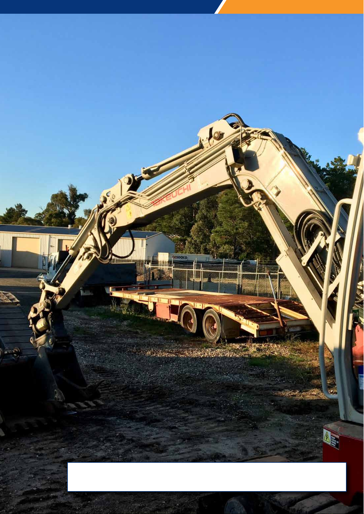
The dipper sensor will need to be located on the dipper arm as low as possible.The higher the sensor is
located on the dipper stick, the more the boom and dipper has to be dropped to catch the beam. Be aware
of the location of hoses and pipes that may inhibit a clear line of sight to the sensor when using the laser
catch function.
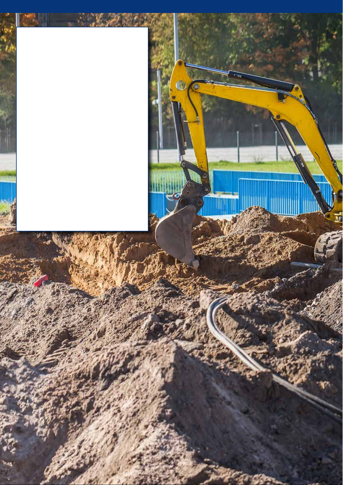
Be aware of the crush zone of the dog bone coming onto the arm as the bucket crowds in and out.
Note also where any auxiliary hoses are being plugged in and out that may spill oil onto the sensor.
These locations are to be avoided avoided if possible.
For more accurate calibration and ease of setup regarding the laser catch function, you may want to
consider installing the dipper sensor using the following directions. This will allow you to manually enter
accurate measurements into the laser calibration setup stage and the system will be maximally accurate
when using the laser catch function.
You will want to rotate the dipper sensor forward (counter clock-wise) slightly 10°-15° from when the
Dipper arm is set at 90° to the ground. This again helps with catching the laser.
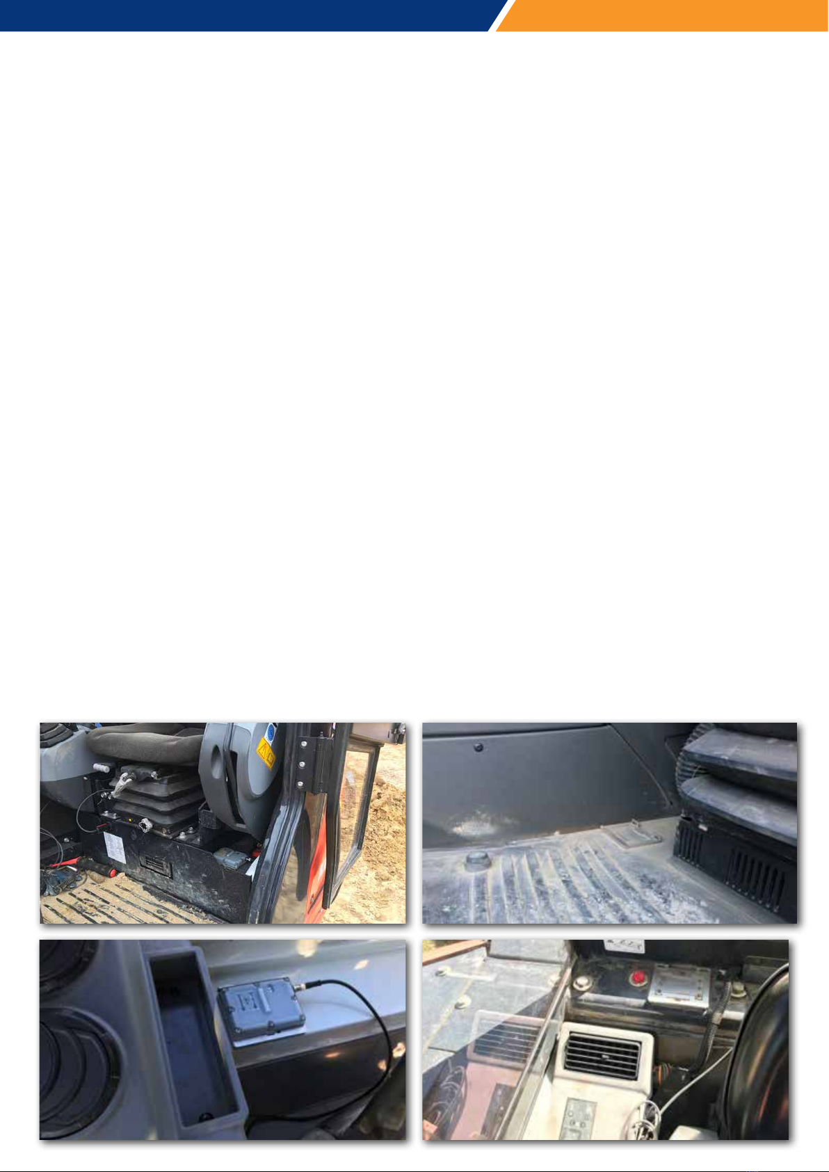
Suitably clean the chosen area with brake cleaner and wipe dry. Clean the surface of the boom as well as
the back of the mounting bracket with the 3M VHB wipes and then stick the bracket onto the boom.
If you are using a secondary mounting plate between the sensor bracket and the machine, screw the
bracket onto the plate and follow the same process as above.
Recommended Installation method of dipper sensor in conjunction with Laser
catch calibration.
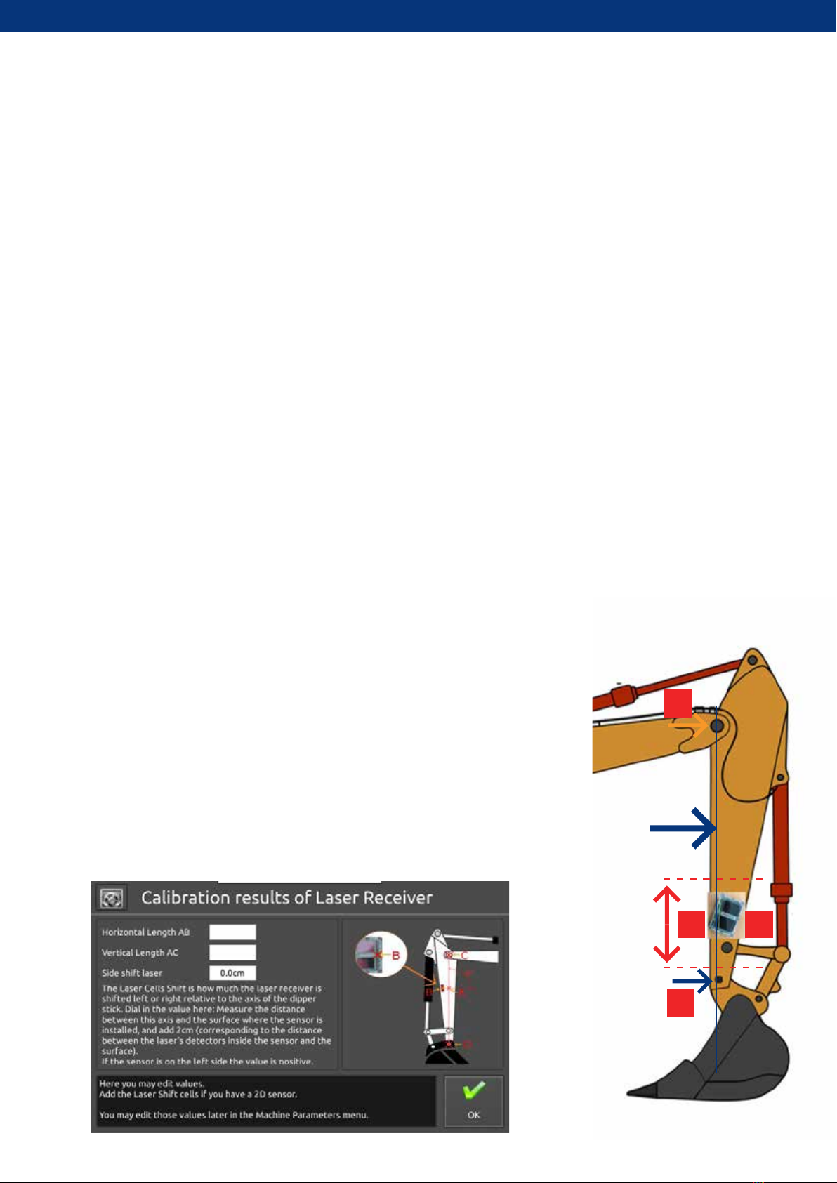
Using a magnetic plumb bob or a string line and magnets, create a line
that is between the centre points of the dipper stick pivot pin and the
bucket pivot pin.
In the bottom 1/3 of the dipper arm, place the sensor on a point so that
the very centre of the laser receiver is on this line, rotate the sensor
forward (away from the cab) slightly by 10-15°.
Take a measurement from the centre of the top pin to the centre of the
sensor, this will be the A-C measurement. The A-B Measurement will be 0.
Enter these measurements via the System Settings menu once the main
iDig calibration steps are complete.
A B
C
D

Stage 2 - Auto Calibration

Stage 2 – Auto Calibration
This process will consist of the following steps:
• Step 1 - Machine setup
• Step 2 - 2D Sensor calibration (pitch, roll and yaw)
• Step 3 - Excavator setup – boom and dipper calibration
• Step 4 - Bucket/quick-link sensor installation and calibration
• Step 5 - Laser functionality calibration
Step 1 - Machine Setup
Select:
“Wizard Mode”
Select:
Relevant Language
Select your units:
“Percent” is recommended for the
Slope Units.
Note: The minimum unit of
measurement for the iDig is 1cm and
as such, no MM option is available.

1. Select Machine Type
This installation document covers the
STANDARD machine type, that is an
excavator with a normal boom and
dipper arm.
Select “Standard”
2. Select Coupler Type
For ease of installation it is
recommended that you select
STANDARD for the coupler type
for all installations, the tilting
hitches or rotating couplers can
be easily added at a later stage.
Select “Standard”
3. Tool Selection
For ease of installation it is
recommended that you select
CLASSIC BUCKET for the tool
type for all installations, the
extra attachments can be easily
added at a later stage.
Select “Classic Bucket”

4. Select 2D option
Select “2D Sensor”
The other options are for 1D
systems without the 2D sensor.
5. Confirm machine setup
Confirm that you choices are
correct, make any changes if
required.
Press “Apply”

Select your machine
from the dropdown list
It is recommended that you
check these measurements,
the same machines and
models can vary depending
on regional OEM distributor.
Manually determine the
Forward and Side Shift
Measurements.
Step 2 - 2D sensor calibration (pitch, roll and yaw)
The calibration of the 2D Sensor requires some measurements to be input onscreen. These measurements
can be automatically entered by selecting your machine from the dropdown list or determined manually
and input in the sections indicated.

The A-B Forward Shift measurement is the horizontal distance between the machine’s center of rotation to
the main boom’s pivot point.
Ensure that the boom is facing directly forward on machines with a swivel boom – exactly 90deg
perpendicular to the cab. An incorrect measurement will result otherwise.
The B-C Side Shift measurement is the horizontal, perpendicular distance between the axis of the main
boom and the machine’s center of rotation.
Ensure that the boom is facing directly forward on machines with a swivel boom – exactly 90deg
perpendicular to the cab. An incorrect measurement will result otherwise.

Manually input the
measurements onscreen
Note:
Negative values are possible.
For example, if the main boom’s
pivot point is BEHIND the
machine’s centre of rotation, the
AB distance is negative.
When in the correct position press
“Next” to begin.
Note:
The 2D sensor is sensitive to vibration
and it is recommended that you have
the machine operating at medium to
high RPM during this alignment process.
Higher RPM reduces the wavelength
of the vibration and allows an accurate
calibration.
You will now calibrate the 2D sensor to the alignment of the machine.
This process will require you to rotate the cab of the machine through 360 degrees, so make sure you have
a clear space around the work area to safely do this.
Begin by aligning the machine facing forward and parallel to the tracks.

You will now be required to align the cab through three further positions, +90, 180 and -90°. You are
aligning the cab to these physical points of the tracks, not to the exact number numbers shown on the
screen.
When you reach each point, press “Next”.
A pop-up will appear during alignment setting. Move to next position when this pop-up is gone.
Once calibration is complete,
press “Done”
+90°
-180°
-90°

Raise the boom and dipper, press “Next”
Step 3 - Excavator setup – boom and dipper calibration
If you’ve not already done so, click on the sensors to the boom and dipper.
This process requires you to fully extend the boom and dipper out in front of the machine so make sure
your work area has enough space to do so safely.
You will also need a tripod, the laser pointer, laser tripod mount, threaded tubes and the magnetic target
tube from your iDig kit.
It is recommended that you remove
the bucket to allow for ease of
calibration.
The system now will automatically detect which side the sensors have been installed on:
Dipper Sensor

Raise the boom and dipper again,
press “Next”
The system now will automatically detect which side the sensors have been installed on:
Boom Sensor
Press “OK” to
continue
Lower the dipper only until the pop-up
appears on screen.