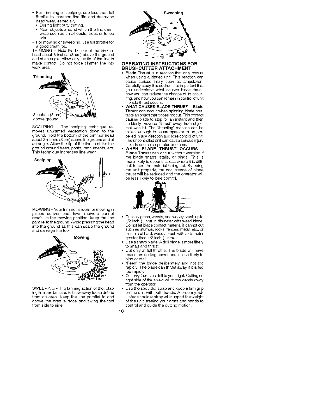
_=WARNING: The blade continues to
spin after throttle is released or engine is
turned off. The coasting blade can throw ob-
jects or seriously cut you if accidentally
touched. Stop the blade by contacting the left
hand side of coasting blade with material al-
ready cut.
Stop coasting
blade by contact
with cut material.
®
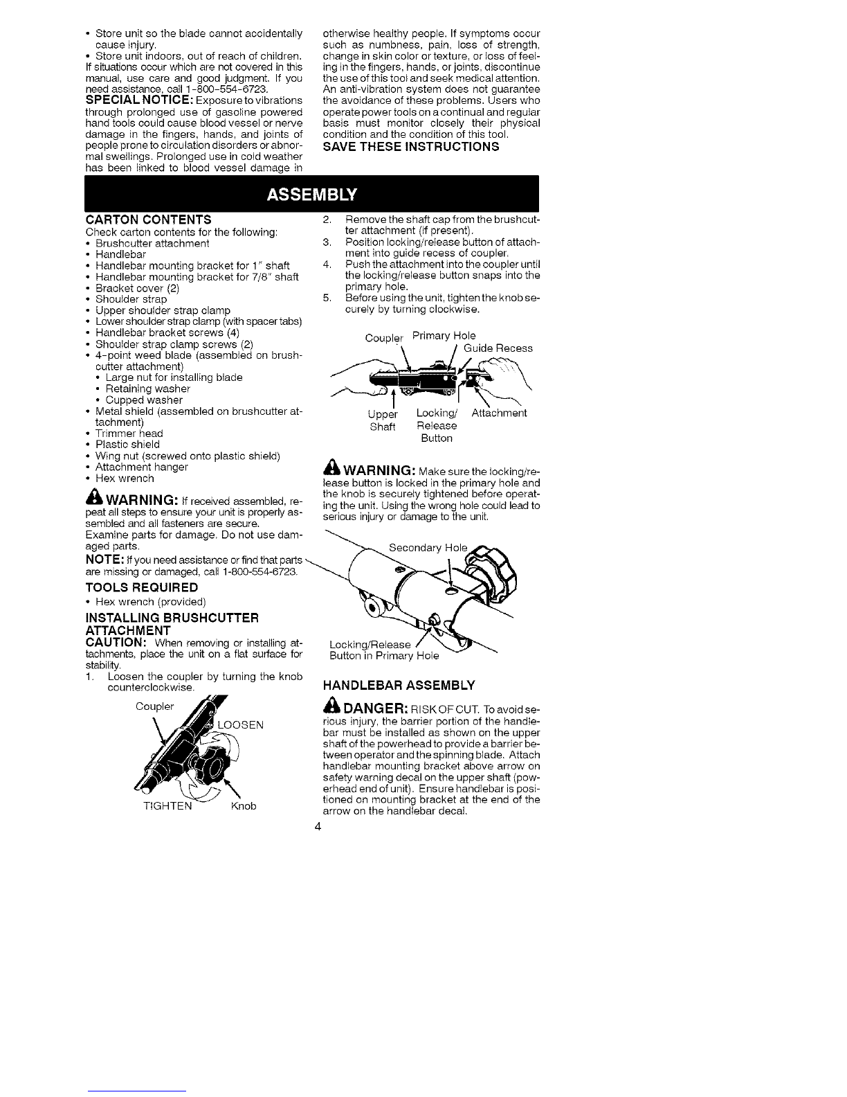
OPERATOR SAFETY
• Dress properly. Always wear safety g_asses
or similar eye protection when operating, or
performing maintenance on your unit (safe-
ty glasses are available). Eye protection
should be marked Z87.
• Always wear face or dust mask if operation
is dusty.
• Always wear heavy, long pants, long
sleeves, boots, and gloves. Wearing safety
leg guards is recommended.
• Always wear foot protection. Do not go
barefoot or wear sandals. Stay clear of spin-
ning line/blade.
• Secure hair above shoulder length. Secure or
remove loose clothing and jewelry or clothing
with loosely hanging ties, straps, tassels, etc.
They can be caught in moving parts.
• Being fully covered also helps protect you
from debris and pieces of toxic plants
thrown by spinning line/blade.
• Stay alert. Do not operate unit when you are
tired, ill. upset or under influence of alcohol,
drugs, or medication. Watch what you are
doh_g; use common sense.
• Wear hearing protection.
• Never start or run the engine inside a closed
room or building. Breathing exhaust fumes
can kill.
• Keep handles free of oil and fuel.
• Always use the handlebar and a properly
adjusted shoulder strap when using brush-
cutter attachment (see ASSEMBLY).
UNIT/MAINTENANCE SAFETY
_ WARNING: Disconnect powerhead
spark plug (or disconnect powerhead from pow-
er source) before performing maintenance.
• Look for and replace damaged or loose
parts before each use. Look for and repair
fuel leaks before use. Keep unit in good
working condition.
• Throw away blades that are bent, warped,
cracked, broken, or damaged in any other
way. Replace trimmer head parts that are
cracked, chipped, broken, or damaged in
any other way before using the unit.
• Maintain the unit according to recommended
procedures. Keep the blade sharp. Never use
flailing devices, wire, rope, string, etc.
• Use only specified Made; make sure it is
properly installed and securely fastened.
• Never start engine with clutch shroud re-
moved. The clutch can fly off and cause se-
rious injury.
• Be sure blade stops turning when engine
idles.
• Make carburetor adjustments with the lower
end supported to prevent the blade from
contacting any object. Hold the unit by hand;
do not use the shoulder strap for support.
• Keep others away when making carburetor
adjustments.
• Use only recommended Poulan PRO ac-
cessories and replacement parts.
• Have all maintenance and service not ex-
plained in this manual performed by an au-
thorized service dealer.
FUEL SAFETY
• Mix and pour fuel outdoors.
• Keep away from sparks or flames.
• Use a container approved for fuel.
• Do not smoke or allow smoking near fuel or
the unit or while using the unit.
• Avoid spilling fuel or oil. Wipe up all fuel
spills before starting engine.
• Move at least 10 feet (3 meters) away from fu-
eling site before starting engine.
• Stop engine and allow it to cool before re-
moving fuel cap.
• Remove fuel cap slowly.
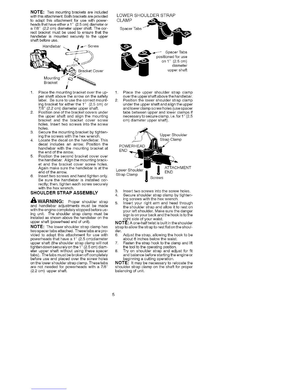
CUTTING SAFETY
,_ WARNING: Inspect the area to be cut
before each use. Remove objects (rocks, bro-
ken glass, nails, wire, string, etc.) which can
be thrown or become entangled in the blade or
trimmer line.
• Keep others including children, animals, by-
standers, and helpers at least 50 feet (15
meters) away. Stop the engine immediately
if you are approached.
• Always keep engine on the right-hand side
of your body.
• Hold the unit firmly with both hands.
• Keepfirm footing and balance. Donot over-
reach.
• Keep blade/trimmer head below waist level.
• Do not raise powerhead engine above your
waist.
• Keep all parts of your body away from spin-
ning line/blade and muffler.
• Cut from your left to your right. Cutting on
the right side of the shield will throw debris
away from the operator.
• Use only in daylight or good artificial light.
• Use only for jobs explained in this manual.
TRANSPORTING AND STORAGE
• Stop the powerhead engine before carrying
unit.
• Keep muffler away from your body.
• Allow engine to cool and secure unit before
storing or transporting it in a vehicle.
• Empty the fuel tank before storing or trans-
porting the unit. Use up fuel left in the carbu-
retor by starting the engine and letting it run
until it stops.
• Store unit and fueI in an area where fuel va-
pors cannot reach sparks or open flames
from water heaters, electric motors or
switches, furnaces, etc.
3